

Page 1
AlphaAnnounce
Installation and Operation Manual
www.jrc.am
Page 2

Contents
I Preface..........................................................................................................5
I.1 Revision History........................................................................................................................................................5
II Warnings and Cautions............................................................................. 6
II.1 Safety Instructions....................................................................................................................................................6
III Introduction................................................................................................7
1 AlphaAnnounce Digital Amplifier............................................................. 8
1.1 Contents of Delivery................................................................................................................................................ 8
1.2 Front Panel...............................................................................................................................................................8
1.3 Rear Panel.............................................................................................................................................................10
1.4 System Description................................................................................................................................................10
1.5 System Components..............................................................................................................................................11
1.5.1 Digital Amplifier Unit......................................................................................................................................11
1.5.2 Transfer Unit................................................................................................................................................. 11
1.5.3 ASV 800 Source/Volume Remote Control Device........................................................................................12
1.5.4 AAI 800 Audio Input and Programmable Control Device.............................................................................12
1.5.5 ADC 200 Dry Contact Output Module..........................................................................................................13
1.5.6 ASI 200 Supervised Input Module................................................................................................................13
1.5.7 AAC 200 Spare Amplifier Module.................................................................................................................13
1.5.8 AEU 100 Line End Unit................................................................................................................................ 14
1.5.9 AlphaAnnounce Microphone Panel...............................................................................................................14
1.6 Digital Amplifier......................................................................................................................................................14
1.6.1 Block Diagram...............................................................................................................................................15
1.6.2 Analogue Audio Inputs..................................................................................................................................15
1.6.3 Amplifier Outputs...........................................................................................................................................16
1.6.4 System and Local Bus..................................................................................................................................18
1.6.5 Setting the Address.......................................................................................................................................18
1.6.6 Control Inputs and Outputs...........................................................................................................................18
1.6.6.1 Control Inputs.......................................................................................................................................18
1.6.6.2 Control Outputs....................................................................................................................................19
1.6.7 Data Connections..........................................................................................................................................19
1.6.7.1 RS-232 Port......................................................................................................................................... 19
1.6.7.2 USB-A Port...........................................................................................................................................19
1.6.7.3 USB-B Port...........................................................................................................................................19
1.6.7.4 Internal USB-A Port.............................................................................................................................19
1.6.8 Configuration of the System......................................................................................................................... 19
1.6.8.1 Device Address....................................................................................................................................19
1.6.8.2 PC Connection.....................................................................................................................................19
1.6.8.3 Audio Input 1-7.....................................................................................................................................20
1.6.8.4 System and Local Bus Out..................................................................................................................20
1.6.8.5 Transfer Unit Ctrl..................................................................................................................................20
1.6.8.6 System Bus and Link (coupled together) and Local Bus.....................................................................21
1.6.8.7 Control In/Out 1-8................................................................................................................................21
1.6.8.8 RS-232 Port......................................................................................................................................... 22
1.6.8.9 Speaker Outputs 1-8............................................................................................................................22
1.6.8.10 24VDC Power Output for ALT 8x8....................................................................................................23
1.6.8.11 48VDC Power Input for Redundant Power Source 2x7A Max.......................................................... 23
2 | Contents
Page 3

1.6.9 Functional Features.......................................................................................................................................23
1.6.9.1 Signal Processing and Routing Characteristics...................................................................................23
1.6.9.2 Digital Signal Processing in Each Input...............................................................................................23
1.6.9.3 Digital Signal Processing in Each Output............................................................................................23
1.6.9.4 Control Buses and I/O Interfaces........................................................................................................24
1.6.9.5 Time Based Functions......................................................................................................................... 24
1.6.9.6 Log Functions.......................................................................................................................................24
1.6.9.7 System Functions.................................................................................................................................24
1.6.9.8 System Monitoring................................................................................................................................24
1.6.10 Technical Specifications..............................................................................................................................25
2 AlphaAnnounce Transfer Unit.................................................................26
2.1 Contents of Delivery...............................................................................................................................................26
2.2 Description..............................................................................................................................................................26
2.3 Front Panel.............................................................................................................................................................26
2.4 Rear Panel.............................................................................................................................................................27
2.5 Connections............................................................................................................................................................28
2.6 Specifications......................................................................................................................................................... 28
3 AlphaAnnounce Backup..........................................................................29
3.1 System....................................................................................................................................................................29
3.2 Connecting............................................................................................................................................................. 29
3.3 Configuration.......................................................................................................................................................... 30
3.4 Use......................................................................................................................................................................... 31
3.5 Volume Adjustment................................................................................................................................................31
3.6 Maintenance...........................................................................................................................................................32
3.6.1 System Testing............................................................................................................................................. 32
3.7 Power Supply Requirements................................................................................................................................. 32
4 AlphaAnnounce Software Configuration............................................... 33
4.1 Software Installation...............................................................................................................................................33
4.1.1 Installation Wizard.........................................................................................................................................33
4.1.2 USB Connection between PC and Digital Amplifier.....................................................................................33
4.2 Uploading and Downloading of Configuration....................................................................................................... 34
4.2.1 Uploading to all System Units through Master Digital Amplifier...................................................................34
4.2.2 Uploading to Digital Amplifier System Units one by one..............................................................................36
4.2.3 Downloading Configuration from System......................................................................................................36
4.3 System Setup using AlphaAnnounce Configuration Software...............................................................................36
4.3.1 Definition of Basic System Info and Password.............................................................................................37
4.3.2 Definition of Digital Amplifier Units...............................................................................................................38
4.3.3 Definition of Announcement Characteristics................................................................................................. 41
4.3.4 Definition of Program Groups.......................................................................................................................43
4.3.5 Definition of DSP Setting..............................................................................................................................43
4.3.6 Uploading or Removing Alarm and Info Messages......................................................................................50
4.3.7 Definition of Control Panel............................................................................................................................52
4.3.8 Definition of Remote Control Units and Devices..........................................................................................54
4.3.9 Definition of System Monitoring....................................................................................................................56
4.3.10 Definition of Control I/O Features...............................................................................................................58
4.3.11 Ambient Noise Compensation.....................................................................................................................59
4.3.12 System Management Using Config-Software............................................................................................. 62
4.3.13 Direct System Commands from PC............................................................................................................65
5 AlphaAnnounce Control Panel................................................................66
5.1 Contents of Delivery...............................................................................................................................................66
5.2 General...................................................................................................................................................................66
3 | Contents
Page 4

5.3 Models....................................................................................................................................................................67
5.4 Front Panel.............................................................................................................................................................67
5.4.1 Front panel of Alpha Announce Control panel............................................................................................. 68
5.4.2 Front Panel of AlphaAnnounce Extension Panel..........................................................................................70
5.5 Rear Panel of AlphaAnnounce Control Panel.......................................................................................................70
5.6 Operation Instructions............................................................................................................................................71
5.7 Configuration.......................................................................................................................................................... 72
5.8 Setup...................................................................................................................................................................... 73
5.8.1 Cabling and Connection................................................................................................................................73
5.8.2 Address and Backlight Power Setting.......................................................................................................... 73
5.8.3 CTRL Output.................................................................................................................................................74
5.9 Technical Specifications.........................................................................................................................................75
Page 5

I Preface
I.1 Revision History
Revision Nr. Description Date
V0.1 For review only 31- March - 2017
V0.2 Minor modifications 4 - April - 2017
V1.0 First release 9 - October - 2017
5 | Preface
Page 6
II Warnings and Cautions
II.1 Safety Instructions
Note This device is intended only for indoor use.
Attention
• Attention: Live voltage
• AlphaAnnounce Transfer Unit has HAZARDOUS LIVE connectors, which are marked with #-symbol. Cable
installations to these connectors are allowed to do by skilled workman only.
• Danger: High voltages
• This device involves high voltage components. Do not open the cover before making sure that power cord is
unplugged. The cover may be opened only by a skilled workman. The unit must be disconnecting from mains
by taken the power cord from its socket.
• Danger: Electric shock
• To avoid fire or electric shock: do not expose the device to rain dropping liquid or high moisture. Do not lay
any object that contains liquid on the unit.
Note The device is allowed to be connected only into a grounded wall socket.
Note Make sure the device is ventilated enough. Do not cover the front or rear ventilation openings of the device
itself or the device cabinet.
Note Several blow-outs of the fuse during a short period are probably a sign of a serious defect. In this case the
defect needs to be located and repaired immediately. Note! The blown fuse may not be changed to a greater
one. In case of serious defect we recommend a prompt contact to Audico Systems service dept. or authorized
Service Company.
6 | Warnings and Cautions
Page 7

III Introduction
This manual is divided in five main parts:
1. Description of the AlphaAnnounce Digital Amplifier
2. Description of the AlphaAnnounce Transfer unit
3. Description of the AlphaAnnounce Backup
4. Description of the AlphaAnnounce Configuration Software
5. Description of the Alpha Announce Control panel
7 | Introduction
Page 8
1 AlphaAnnounce Digital Amplifier
1.1 Contents of Delivery
The delivery of Digital Amplifier Unit contains:
• Digital Amplifier Unit
• IEC power cord for a grounded wall socket
• USB-cable USB(A) / USB(B)
• Flash-memory stick containing configuration software and User Manuals
• Printed copy of user manual
• Terms of warranty and the warranty form
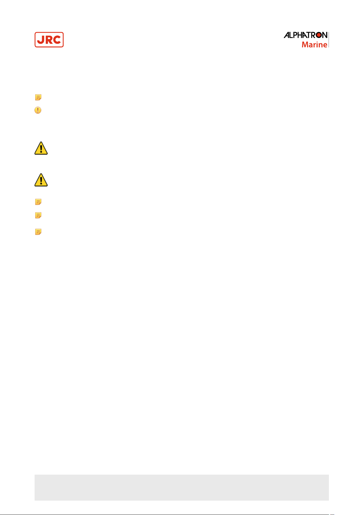
1.2 Front Panel
1. USB-B connector for PC connection. Used for system programming and administration.
2. Input signal indicator. Blue light indicates the presence of audio signal in each channel; red light instead indicates a
too high level of the input signal.
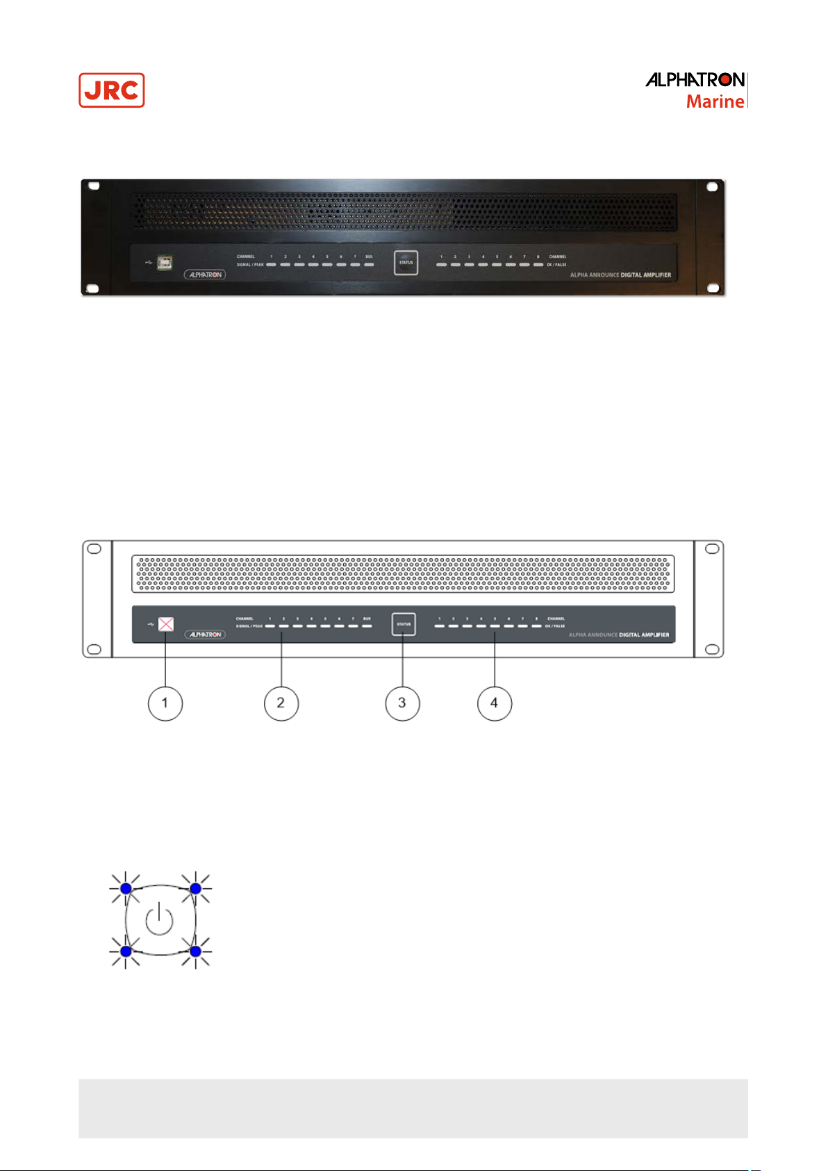
3. On/Stand-By button and status indicator. In case the operation is allowed, a press of button switches the system to
stand-by mode. Another press of button returns the system to active mode.
In normal operation four blue corner LED's are active.
When system is in stand-by mode, the blue LED's are blinking.
8 | AlphaAnnounce Digital Amplifier
Page 9
When system is fault monitored and one or more faults are detected, the blue LED's are switched off and four "fault"
yellow led start blinking.
When one or more system fault is active, on Stand-By mode yellow "fault" LED's are on and blue LED's are blinking.
When all system faults are cleared, yellow "fault" LED's are switched off. Faults can be cleared either from
Microphone panel or from configuration program when PC is connected. The triggering of control input function
“No monitoring” also clears faults. All faults, excluding system fault are cleared automatically if the cause of fault
disappears.
4. Fault indicator for amplifier or loudspeaker line. Blue led indicates the presence of audio signal in loudspeaker line.
Note Indicator's operation is not real time and blue LED's will remain for couple of seconds when signal is
not present anymore.
When amplifier and loudspeaker line monitoring is in use, faults in any line or amplifier is indicated by a yellow led.
9 | AlphaAnnounce Digital Amplifier
Page 10
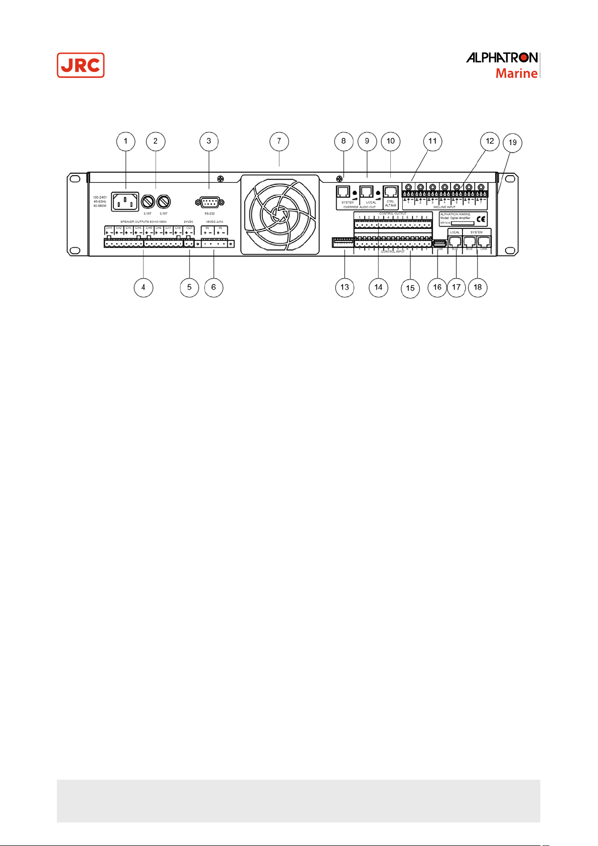
1.3 Rear Panel
1. IEC power cord. Connect only to grounded wall socket.
2. Device fuses, 2 pcs. of T3,15A 5x20mm. Always use correct fuse value. Before changing a fuse disconnect mains.
3. RS-232 Serial port service purpose
4. Amplifier output connectors to loudspeakers or Transfer Unit
5. 24V Power supply output
6. +48VDC External power supply input
7. Electric fan with dust filter
8. System bus program transfer output (0dB)
9. System bus program transfer output (0dB)
10.Transfer Unit priority output control
11.Gain trimming potentiometers for audio inputs 1...7. Input sensitivity can be adjusted between - 40…+6 dBu.
12.Connectors for electrically balanced audio inputs 1...7
13.8-Pole DIL-switch. Used e.g. for address setting of each Digital Amplifier Central unit.
14.Connector for control outputs
15.Connector for control inputs
16.USB-A connector. Connection for USB memory, Ethernet or WLAN device.
17.Local Bus connector. Local Bus is designed for AVEC product family devices and mountings
18.System Bus connector. System Bus is designed for AlphaAnnounce product family devices and mountings.
Furthermore, System Bus connects different Central units together.
19.+48V phantom voltage selection switch for audio inputs 1-7
1.4 System Description
Digital Amplifier System Unit is central of the innovative AlphaAnnounce product concept.
Digital amplifiers are reliable and their efficiency is excellent (>90 %). Good efficiency means considerably smaller heat
production and smaller capacity requirement for backup power supplies needed for evacuation system.
The fundamental function of sound reproduction and evacuation system is to transmit sound information - occasionally in
extreme conditions.
AlphaAnnounce has been designed to fulfill requirements of standards EN-60849 and EN54-16 and it is certificated to
fulfill standards demands by companies having certification authority.
All properties and functions for system is configured with Configuration Software and loaded to system through USB port.
10 | AlphaAnnounce Digital Amplifier
Page 11
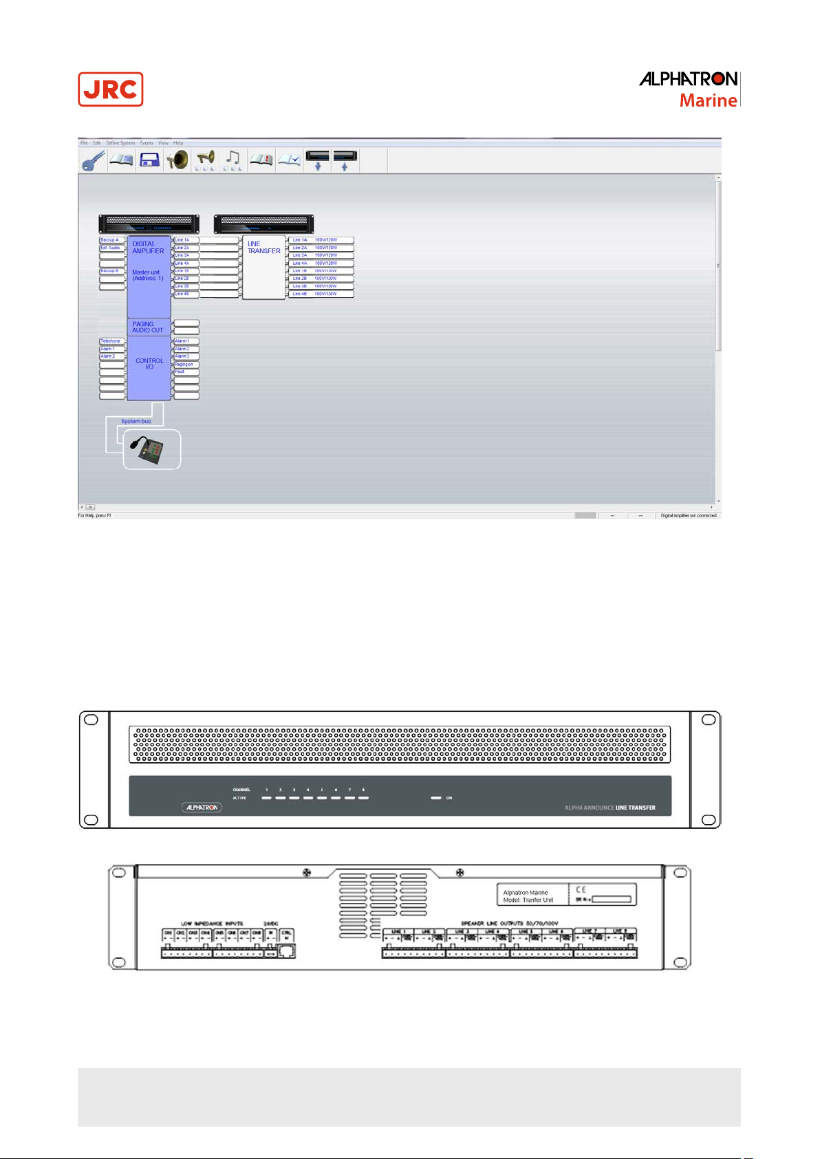
Figure 1: An example diagram of the AlphaAnnounce solution
1.5 System Components
1.5.1 Digital Amplifier Unit
See Digital Amplifier on page 14
1.5.2 Transfer Unit
Line Transfer adapts 8 ohm amplifier outputs suitable for 100V loudspeakers. Maximum load is 120W/output. Unit also
24VDC outputs for priority relays or spare amplifier control. Each output can handle maximum load of 1A/24VDC.
11 | AlphaAnnounce Digital Amplifier
Page 12
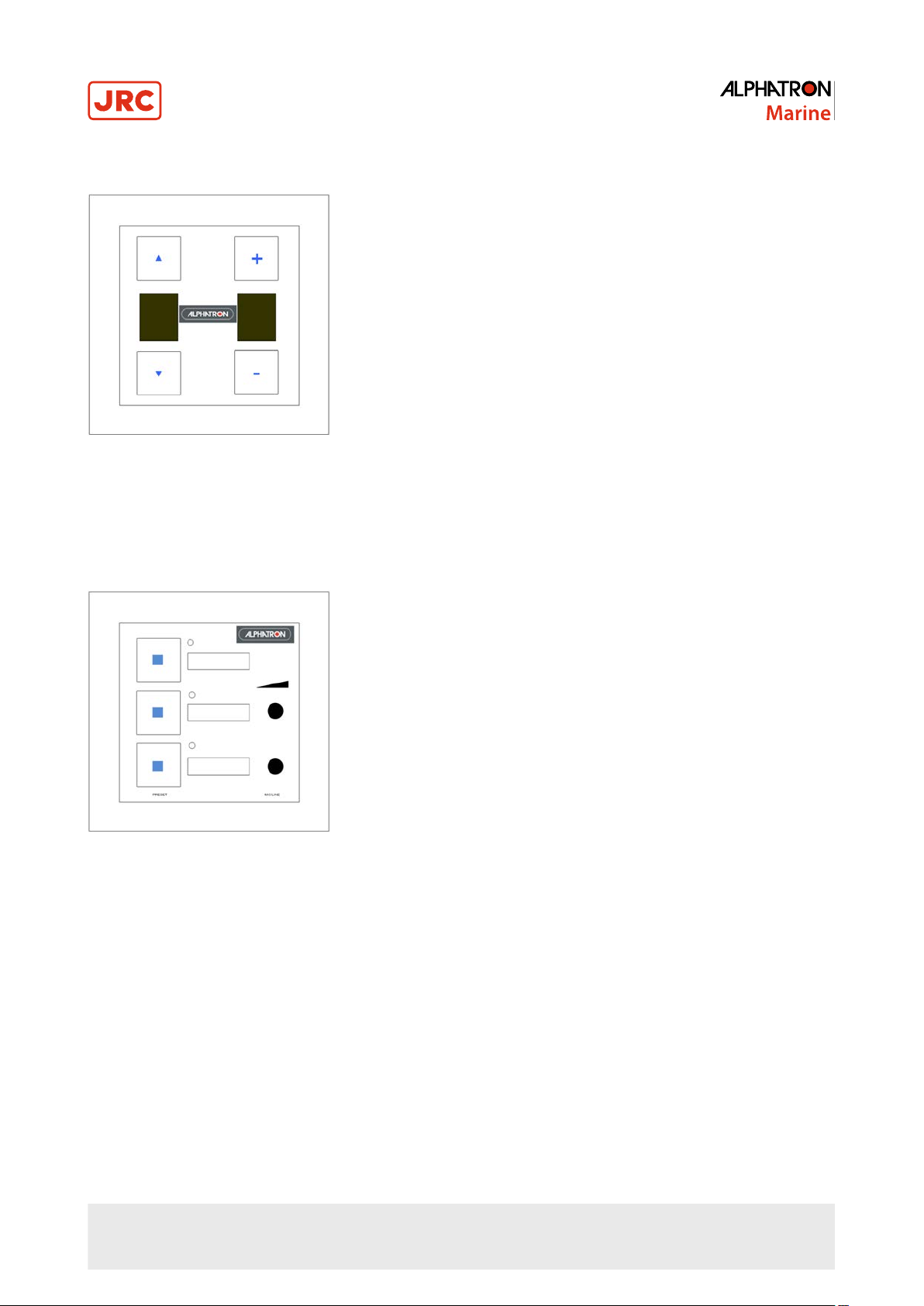
1.5.3 ASV 800 Source/Volume Remote Control Device
• Select source and adjust volume for one program group
• Up to 32 control units to System and 8 to Local Bus
• Connection to Local or System bus with TIA/EIA-568 cabling (CAT5/6)
• Can be mounted to a wall box
1.5.4 AAI 800 Audio Input and Programmable Control Device
• Symmetric analog audio input with 3.5mm² stereo plug
• Volume adjust for audio input
• +24V Phantom output for condenser microphone
• Connector for external XLR connector
• 3 Programmable function keys. For example audio input activation, call off or message start
• Up to 32 control units to System and 8 to Local Bus
• Connection to Local or System bus with TIA/EIA-568 cabling (CAT5/6)
• Can be mounted to a wallbox
12 | AlphaAnnounce Digital Amplifier
Page 13
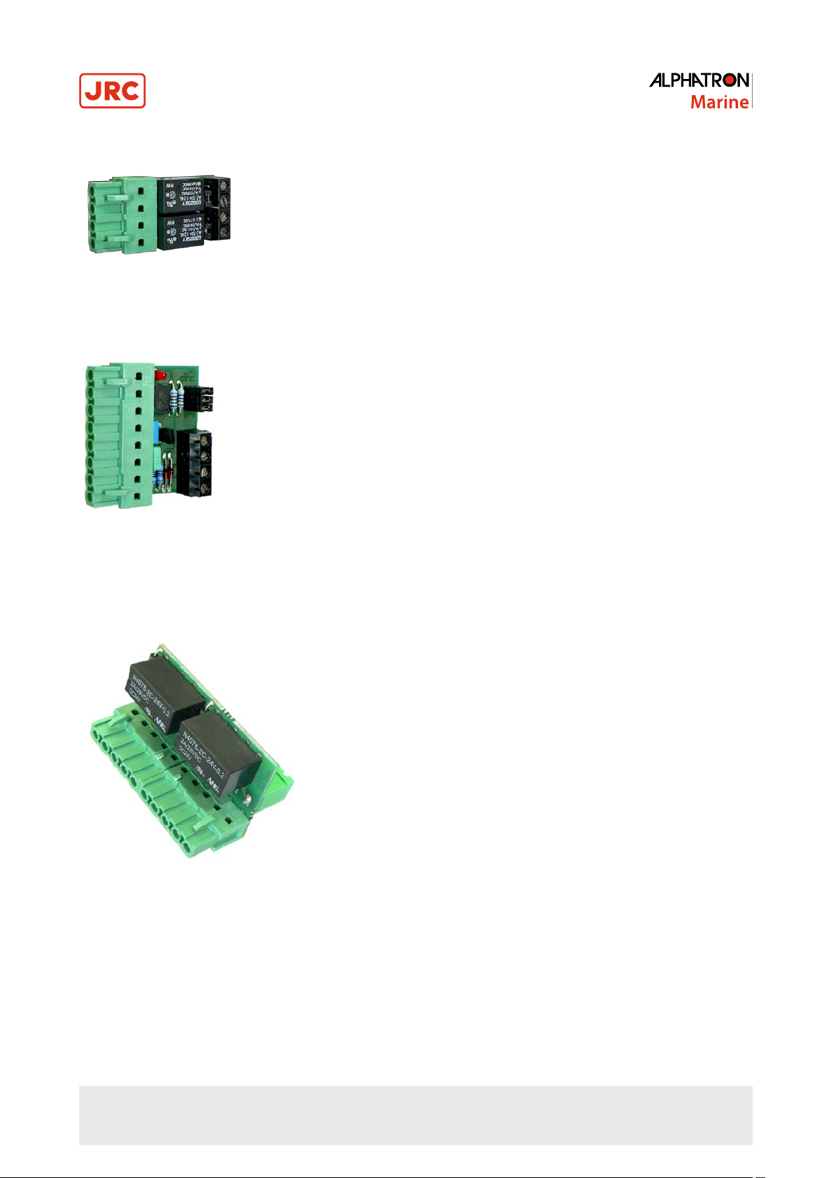
1.5.5 ADC 200 Dry Contact Output Module
Connected to Digital Amplifier control outputs when potential free control output is needed. ADC 200 also has got circuit
to implement monitored control line together with ASI 200.
1.5.6 ASI 200 Supervised Input Module
Connected to Digital Amplifier control inputs when supervised control input is needed. Only to be used with ADC 200
output adapter.
• 2 Monitored inputs
• Fault outputs when control cable is disconnected or short circuit
1.5.7 AAC 200 Spare Amplifier Module
Connected to ALT 8x8 output.
• 1 Spare amplifier input for two Transfer Unit outputs
• Spare amp link to next module or option for second spare amp input
13 | AlphaAnnounce Digital Amplifier
Page 14
1.5.8 AEU 100 Line End Unit
AEU 100 is used when speaker line monitoring is required. Unit is connected to the end of the line. It is suitable for 50,
70 or 100 Volt level speaker lines. 8 ohm line does not need the unit.
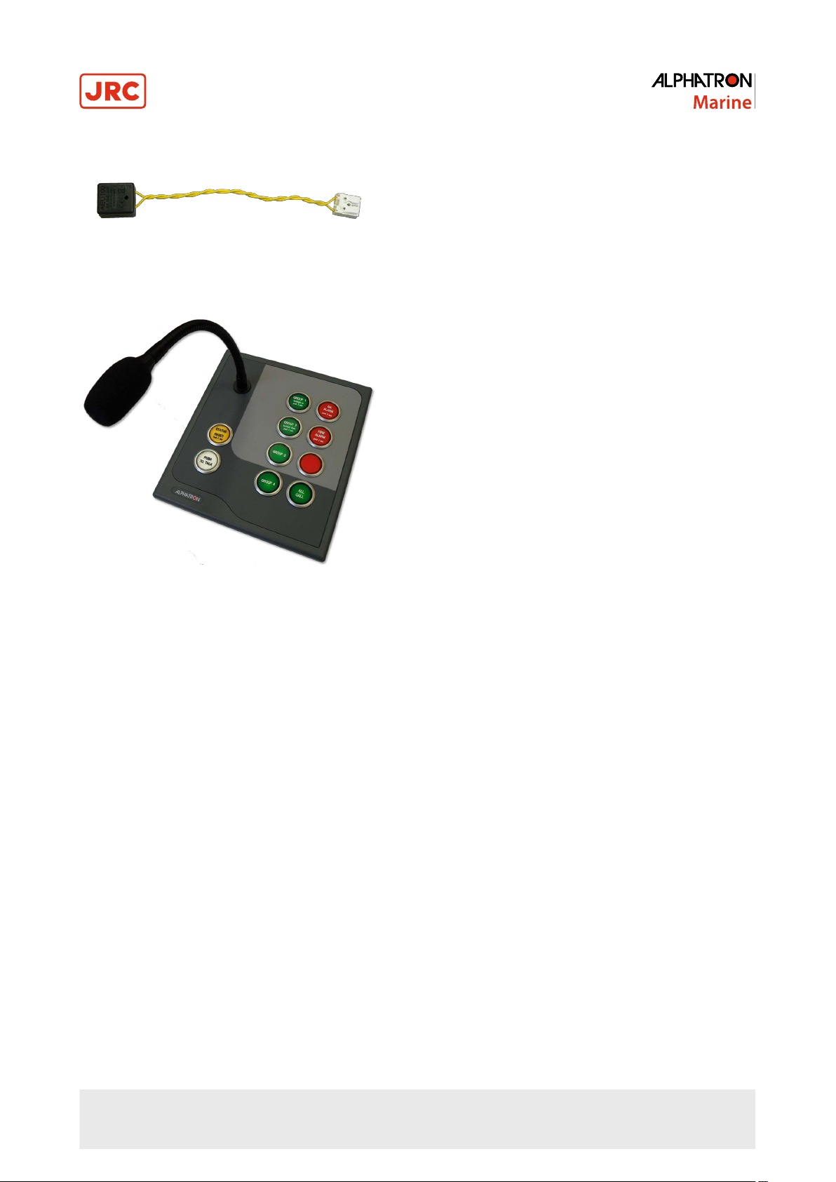
1.5.9 AlphaAnnounce Microphone Panel
• Monitored goose neck or hand microphone
• 8 -programmable function keys
• Backlight dimming
• 3.5mm² stereo plug for external program source e.g. iPod, laptop
• Speaker mute output (or fault output as alternative function)
• Up to 32 control units to system
• 2 Data bus outputs for redundant systems
• Connection to Local or System bus with TIA/EIA-568 cabling (CAT5/6)
1.6 Digital Amplifier
14 | AlphaAnnounce Digital Amplifier
Page 15
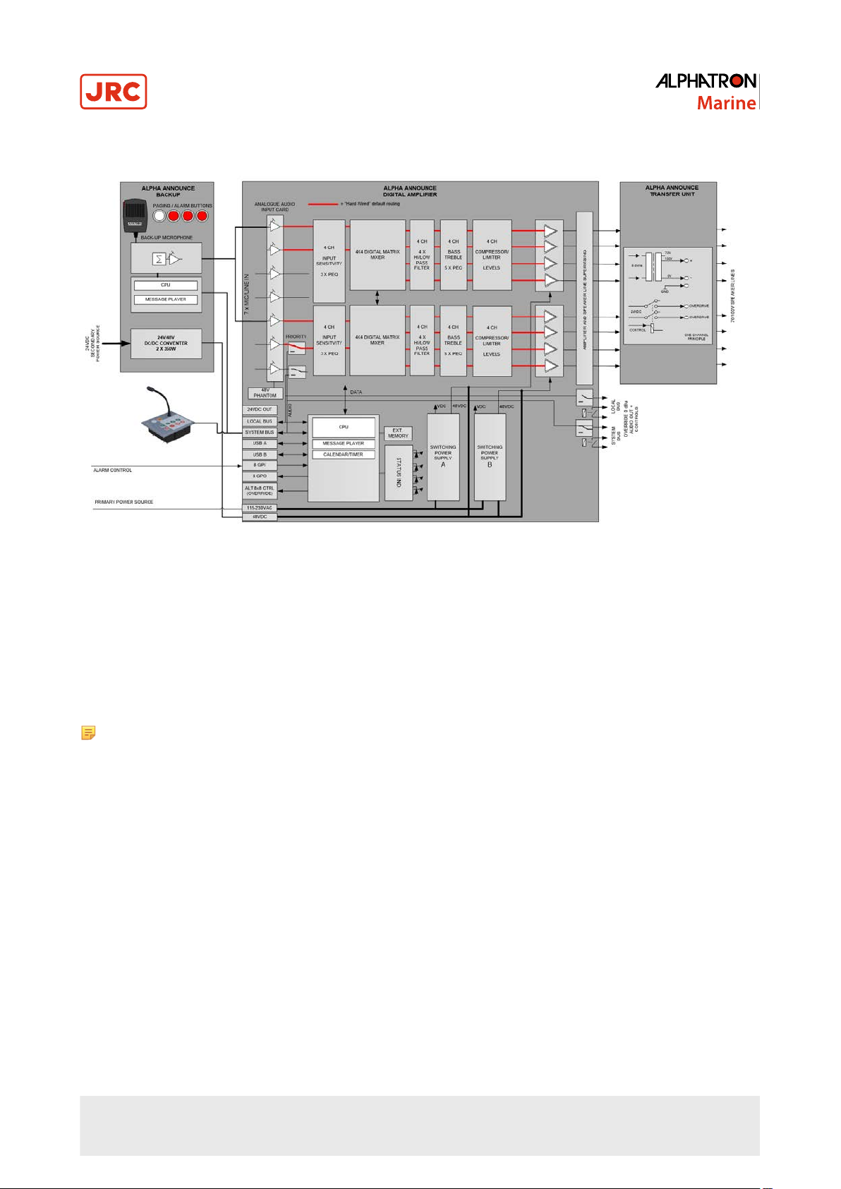
1.6.1 Block Diagram
Figure 2: Internal block diagram of Digital Amplifier
1.6.2 Analogue Audio Inputs
Digital Amplifier has 4 electrically balanced analogue audio inputs for external program sources. Audio input can be
programmed to be microphone (-45dB) or line level (+6dB) inputs. +48VDC Phantom voltage for condenser microphones
can be selected with dip switch. Each input has also tool adjustable input sensitivity to balance program sources.
Adjustment knobs are located above each input connector. Selection for +48VDC Phantom is located on the left side of
Digital Amplifier.
The input connector is a detachable terminal block of which max. conductor’s area is 1.5 mm².
Note Program input 6 is muted during Local Bus paging and program input 7 during System Bus paging.
15 | AlphaAnnounce Digital Amplifier
Page 16
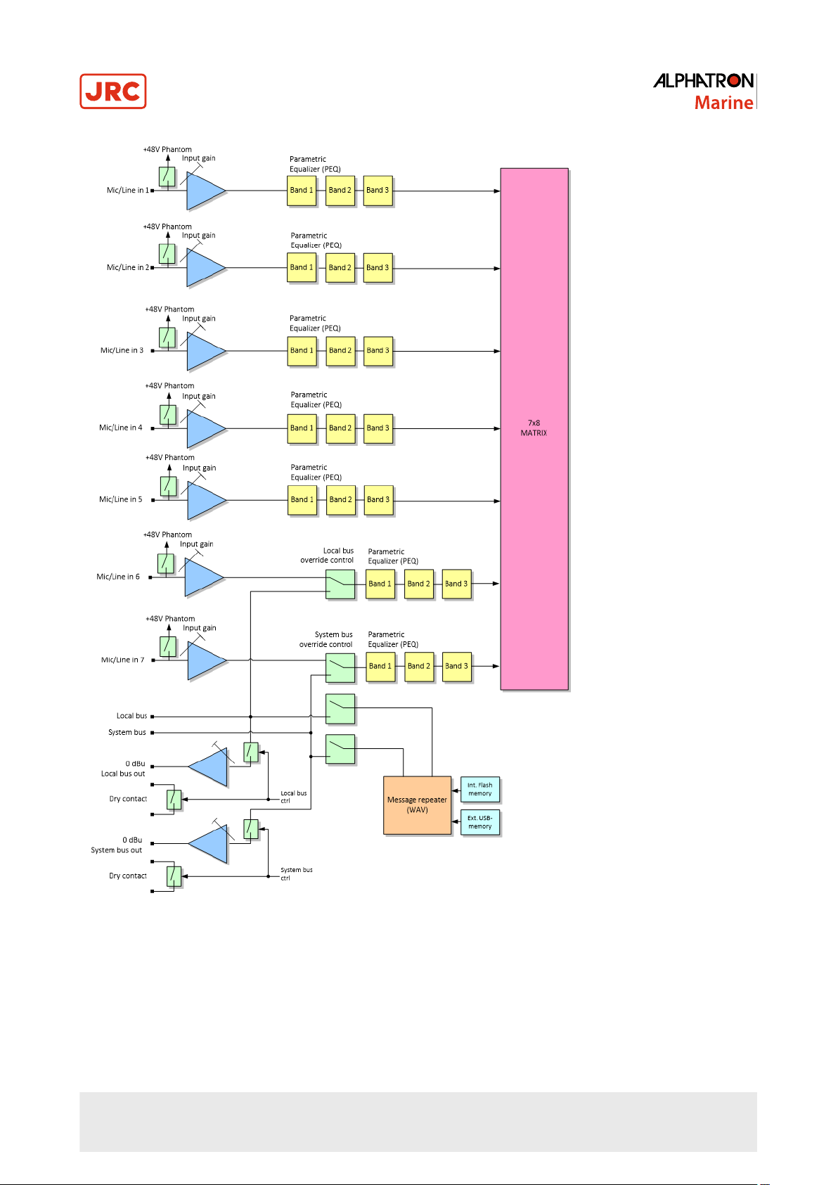
Figure 3: Analogue audio input block
1.6.3 Amplifier Outputs
Digital Amplifier includes eight digital amplifiers having versatile digital signal processing properties. Low ohm (8 ohm)
loudspeakers can be connected to speaker outputs.
When line level loudspeakers are used, outputs are connected to Line Transfer Unit's (see Figure 5: Digital Amplifier and
Transfer Unit configured for 3x80W, 1x160W and 1x240W on page 17). Each output can handle 120W/100V load. If
16 | AlphaAnnounce Digital Amplifier
Page 17
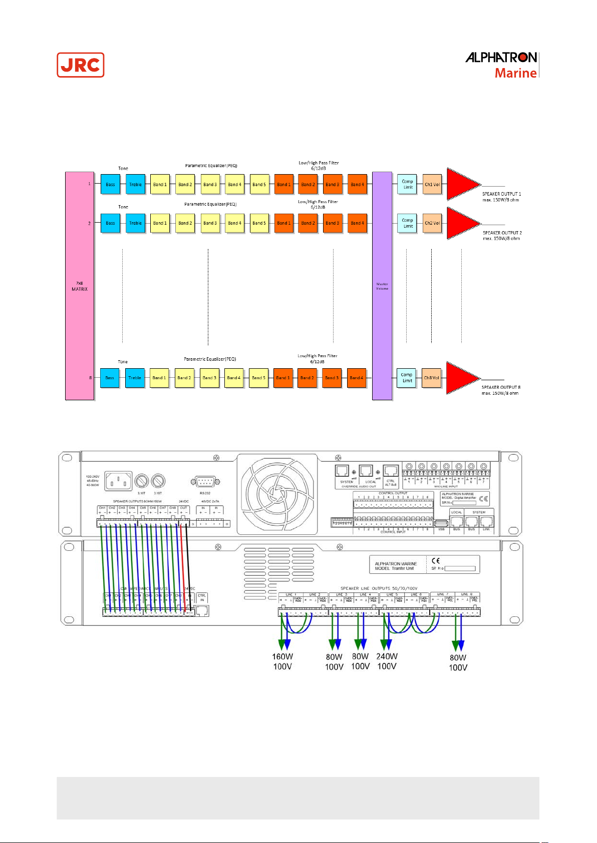
speaker line load is more than 120W outputs several outputs can be combined together and make Locked group. With
Locked groups 160W or 320W lines can be used. Total output power for one Digital Amplifier unit is 640W.
Locked group is defined with configuration software. All DSP settings from first locked group amplifier is copied to other
amplifiers in the group.
Figure 4: Amplifier block
Figure 5: Digital Amplifier and Transfer Unit configured for 3x80W, 1x160W and 1x240W
Output line voltage level can be changed inside the unit to from 100V to 70V.
17 | AlphaAnnounce Digital Amplifier
Page 18
1.6.4 System and Local Bus
Both System and Local bus have 4 signal pairs: audio and data power supplies, audio and data signals.
System Bus is a systems wide data bus where all Digital Amplifier units are connected. Paging units and control panels
can be connected to either System or Local Bus. If redundant Bus for the system is needed, Local Bus can be extended
to be as a redundant System Bus.
Data bus cabling can be done with CAT5 or CAT6 category cable, but also other cable types with twisted pairs can be
used.
All paging and control are powered via buses and no external power supplies are needed.
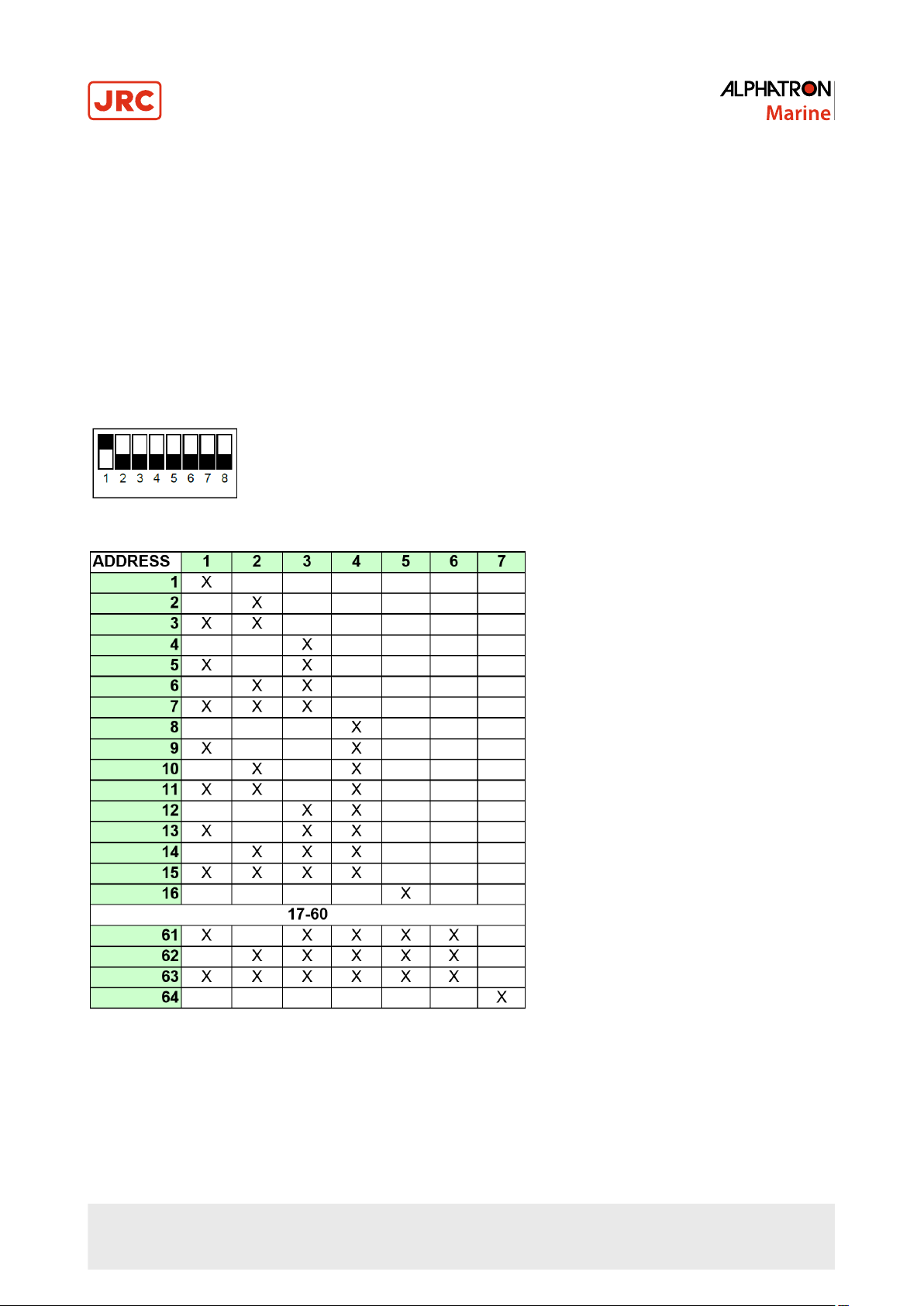
1.6.5 Setting the Address
Each units get own address from configuration program. Address for Digital Amplifier is set with back panels dip switch.
Address must be set before power-up.
DIL-switch at ON position
1.6.6 Control Inputs and Outputs
1.6.6.1 Control Inputs
Digital Amplifier has got eight programmable logic inputs. Opto-coupled inputs are controlled with potential free contacts
(relay or switch). Inputs can be programmed to activate either open or close contact. Programmable functions are:
automatic messages, preset changes, call off functions and various monitoring and status functions.
18 | AlphaAnnounce Digital Amplifier
Page 19

1.6.6.2 Control Outputs
Digital Amplifier has got also eight programmable logic outputs. Control outputs are open collector outputs and they
have +24VDC output that can be used to drive directly +24V relays. Each output can control a maximum load of 300mA.
Outputs can be used to control lights, alarm bells, start audio substation etc.
Details of the control input/output programming is described in the AlphaAnnounce Software Configuration on page
33.
1.6.7 Data Connections
1.6.7.1 RS-232 Port
Service port.
1.6.7.2 USB-A Port
USB port for external USB-memory containing WAV formatted alarm and info messages. Also USB-RS232/485 adapters
can be connected when connection to external system is needed. Through USB-HUB multiple devices can be connected
simultaneously.
1.6.7.3 USB-B Port
Delivery includes USB-AB cable that is used for connection to PC. Configuration made with Configuration Software
is loaded to system through Digital Amplifier with address 1 which will resend configuration to all other units through
System bus.
1.6.7.4 Internal USB-A Port
Digital Amplifier contains one internal USB port which can be used when USB-memory is needed to store out of sight.
When USB-memory is connected to both internal and external port, internal port is always primary.
1.6.8 Configuration of the System
Configuration and commissioning of the system requires that correct version of configuration software is installed to PC
and Digital Amplifier USB drivers are installed correctly.
Details of how to setup and use program is described in the AlphaAnnounce Software Configuration on page 33.
1.6.8.1 Device Address
Setting of device address has been described in Setting the Address on page 18. Digital Amplifier with address 1 is
the master unit for the system. In case where there are two or more units attached to system, the device with address 2
can be programmed to act as reserve master for the system. It takes control if master unit fails (Master Change Over).
1.6.8.2 PC Connection
1. Connect USB cable between PC and front panel USB connector
2. Switch on the powers
3. After start-up of the device open Configuration Software
4. When you are building new system, use setup wizard to create new system template
5. If you are making changes to old system open project file. If you don’t have project file, open any project and
download configuration from Digital Amplifier to PC.
6. Active connection between PC and Digital Amplifier is shown on status bar with text ”Digital Amplifier Connected”
7. Configuration must be uploaded to Digital Amplifier before changes takes place
Note Internal clock must be set with Configuration Software to get correct timestamps to action and fault log.
Also Time based events won’t activate correctly if internal clock is not set.
19 | AlphaAnnounce Digital Amplifier
Page 20
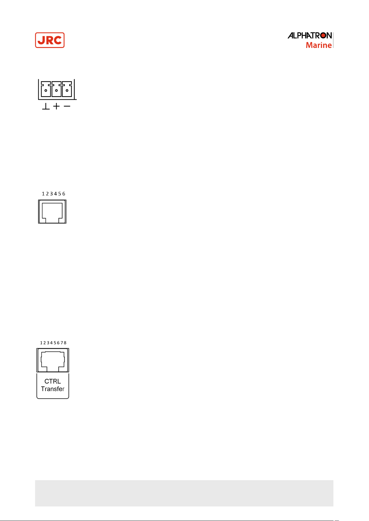
1.6.8.3 Audio Input 1-7
Removable 3-pin terminal block connector. Maximum conductor area that can be used is 0.75 mm².
Pin Order
1
2 + Audio +
3 - Audio -
⊥
Ground
1.6.8.4 System and Local Bus Out
RJ-11 connector
Pin Order
1 Ground
2 Audio +
3 Audio 4 Relay contact NC
5 Relay contact NO
6 Relay contact Common
1.6.8.5 Transfer Unit Ctrl
RJ45 - connector
1 Line 1 Open collector control
2 Line 2 Open collector control
- - - - - - - - - - - - - - - - - - - - - - -
8 Line 8 Open collector control
20 | AlphaAnnounce Digital Amplifier
Page 21
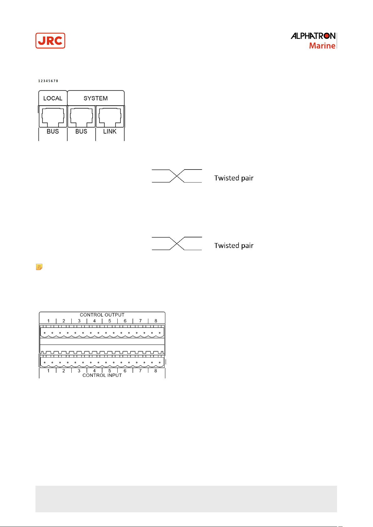
1.6.8.6 System Bus and Link (coupled together) and Local Bus
Pin Order
1 System/Local audio +
2 System/Local audio -
3 Audio GND
4 Digital GND
5 +12V
6 +24V
7 Data (A)
8 Data (B)
Note Audio and data signals must be always connected to own twisted pairs.
1.6.8.7 Control In/Out 1-8
Removable 16-pin terminal block connector for both control input and output. Maximum conductor area that can be used
is 2.5 mm².
Control Input
1 Control 1
2 +12V
3 Control 2
4 +12V
- - - - - - - 15 Control 8
16 +12V
21 | AlphaAnnounce Digital Amplifier
Page 22
Control Output
1 Control 1 (Open Collector)
2 +24V
3 Control 2
4 +24V
- - - - - - - 15 Control 8
16 +24V
1.6.8.8 RS-232 Port
Pin Order
1 2 Rx Data
3 Tx Data
4 5 GND
6 7 8 9 -
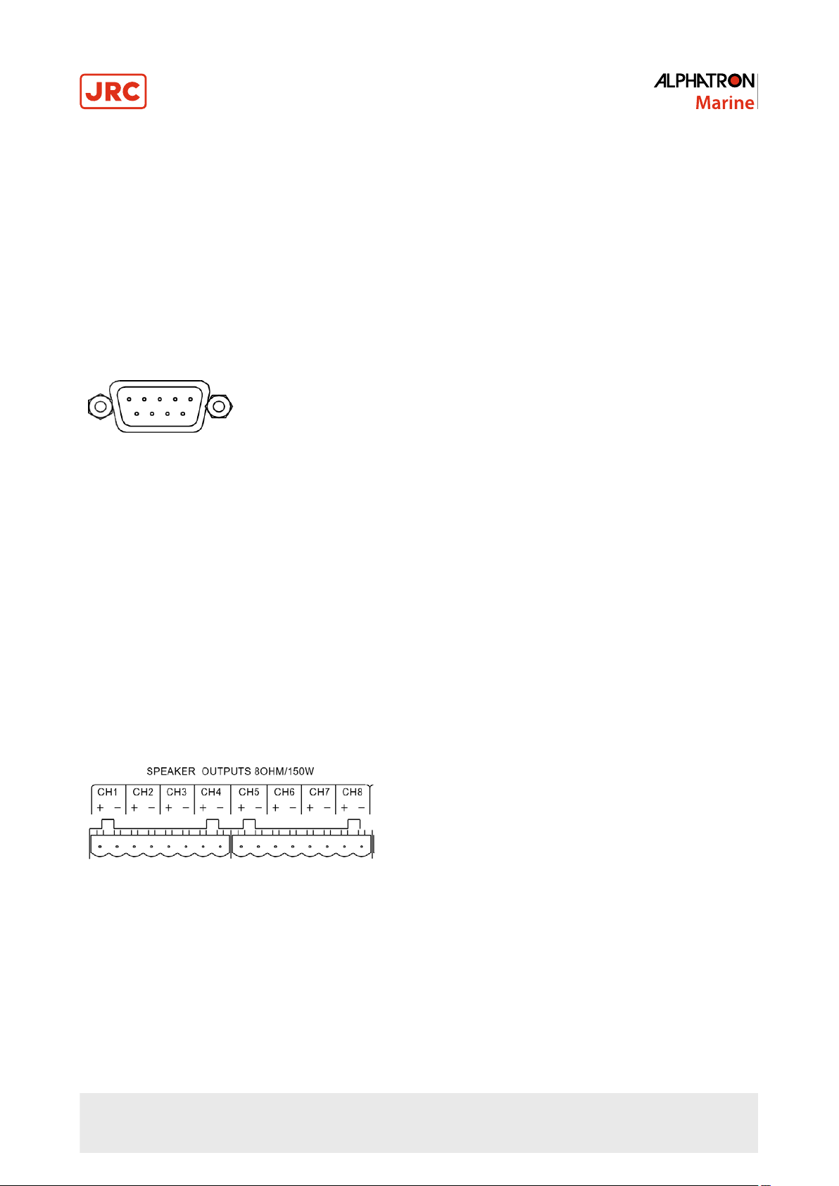
1.6.8.9 Speaker Outputs 1-8
Removable 8-pin terminal block connector. Maximum conductor area that can be used is 2.5 mm².
22 | AlphaAnnounce Digital Amplifier
Page 23
Pin Order
1 Output Channel 1 +
2 Output Channel 1 3 Output Channel 2 +
4 Output Channel 2 -
- - - - - - - - - - - - - - 15 Output Channel 8 +
16 Output Channel 8 -
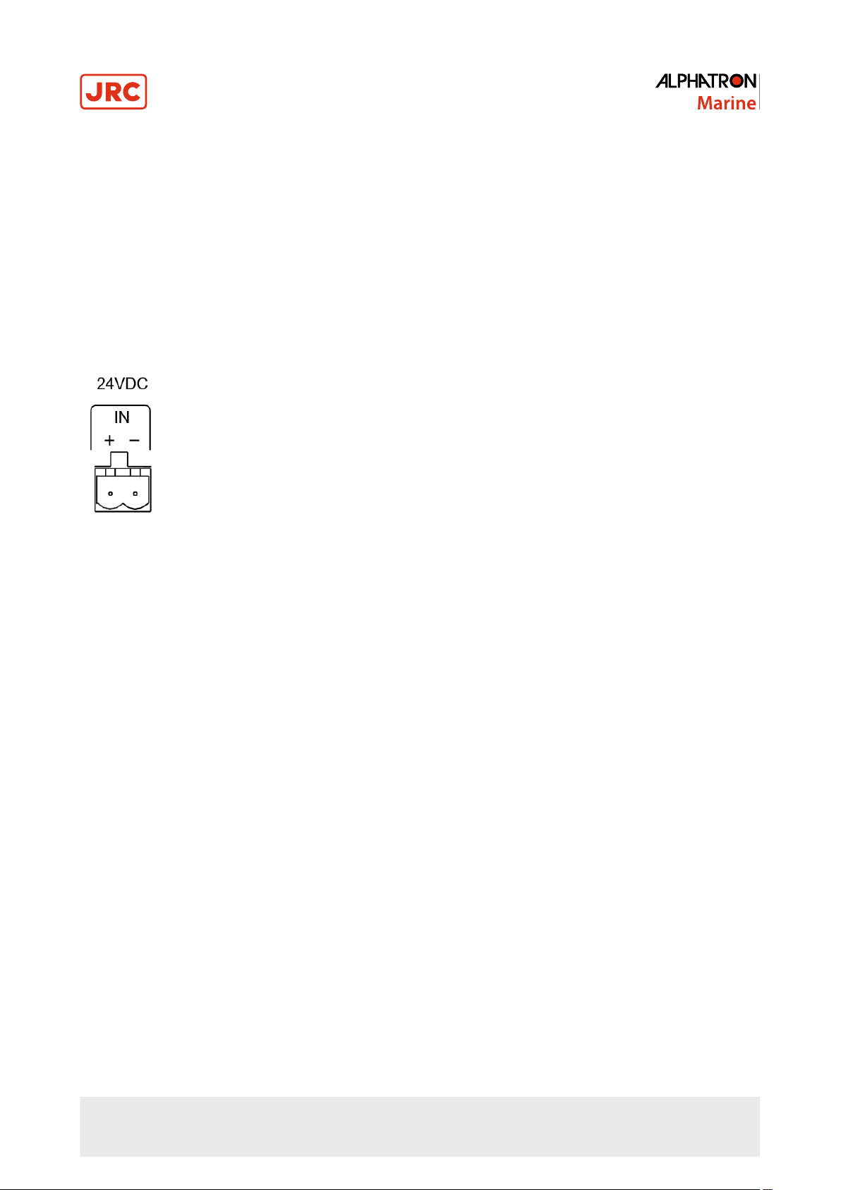
1.6.8.10 24VDC Power Output for ALT 8x8
1 +24VDC
2 GND
1.6.8.11 48VDC Power Input for Redundant Power Source 2x7A Max
1.6.9 Functional Features
1.6.9.1 Signal Processing and Routing Characteristics
• True digital signal path and processing, digital power amplifiers, efficiency up to 92%
• Analogue audio inputs, either microphone to line sensitivity
• Phantom voltage for microphones
• Built-in WAV message player, up to 128 messages
1.6.9.2 Digital Signal Processing in Each Input
• 3-band parametric equalizer
• Digital routing to any output channel, level control
1.6.9.3 Digital Signal Processing in Each Output
• Tone control, bass & treble
• 5-band parametric equalizer
• Four filter blocks with freq. adjustment, selectable high- or low-pass function, slope 6/12 dB/Oct.
• Compressor/limiter
• Level control
23 | AlphaAnnounce Digital Amplifier
Page 24

1.6.9.4 Control Buses and I/O Interfaces
• Local Bus interface for paging units and control devices. Used also as a redundant bus for System Bus
• System Bus interface for paging and control devices
• System Bus link out to next Digital Amplifier unit
• USB-B connector for PC interface
• USB-A connector external memory or RS232/485 adapters
• 8 programmable control inputs
• 8 programmable control outputs
• Control output to transfer unit
• RS-232 Serial port for service
1.6.9.5 Time Based Functions
• Internal clock and calendar
• 25 Years automatic summer/winter time setting
• Up to 125 time based events
1.6.9.6 Log Functions
• System Events Log
• System Error Log
1.6.9.7 System Functions
• System is expandable by connecting up to 64 Digital Amplifier units together via System or Local Bus
• Each Digital Amplifier has unique selectable address
• Up to 512 speaker lines, paging zones and audio program groups for background music
1.6.9.8 System Monitoring
• Equipment and system monitoring according to the EN54-16
• Automatic master change over function in case of master fault
• Automatic spare amplifier change
• Power supply voltages
• Temperature monitoring
• Fan motor monitoring
24 | AlphaAnnounce Digital Amplifier
Page 25

1.6.10 Technical Specifications
• Analogue input 1…7, sensitivity -45 dBu … + 6 dBu
• Analogue input impedance (balanced) 20 kohm
• System and Local Bus audio (balanced) + 6dBu
• Digital message signal format (WAV) 16bit 32 or 44.1 kHz sample rate
• Frequency response -1 dB 20-20kHz
• S/N level 96 dBA
• THD+N @1W/1 kHz < 0.05%
• Dynamic Power @8
• Continuous power @8 Ω or 100V
all ch. driven < 1 %THD 8 x 80W RMS
• Output power for 70/100V 8 outputs (Transfer Unit) Total 640W, 120W RMS max./channel
• Peak wattage capability 150W @ 8 ohm
• Dynamic range 105 dB
• Mains operating voltage 100-240VAC, 47-63Hz
• Mains type connector Class I
• Power consumption at VAC 40W-990W
• Power factor at full load 0.95
• Main fuses 5x20mm 2 x T3.15A
• DC Power Inlet 48VDC, 2x7A max.
• Operation temperature -5 …+50 ºC
• Operation humidity 20 …90%
• Measurements W x H x D 485mm x 86mm x 375mm
• Net weight 8.4 kg
Ω
8 x 150W max.
180W @ 6 ohm
260W @ 4 ohm
RH non-condensing
Note Any changes can be done without a notice.
25 | AlphaAnnounce Digital Amplifier
Page 26

2 AlphaAnnounce Transfer Unit
2.1 Contents of Delivery
The delivery of Transfer Unit contains:
• Transfer Unit
• 1m RJ45 (LAN) control cable
• Connection cable Digital Amplifier speaker outputs to Transfer Unit audio input
• Rear panel connectors for outputs
• User Manual
2.2 Description
The Transfer Unit has 8 internal transformers to convert the 8 Ω loudspeaker outputs of the Digital Amplifier unit into
constant voltage lines (100 or 70V) for loudspeakers having transformers. The default output voltage is 100 V; contact
your authorized service center to change the output voltage to 70V if necessary. If the required power for a loudspeaker
line is higher than 80W, it will be necessary to combine more outputs to make a Locked Group (controlled as a single
output).
‘OVERRIDE’ 24 V dc outputs are available for override relays. If AAC 200 Amplifier Change Modules are used to have
faulty amplifier change-over feature, override voltage is not available.
2.3 Front Panel
1. ‘PRIORITY’ LED ( x 8, 1 per each output) indicating the activation of the ‘OVERRIDE’ 24 V dc command when paging
or faulty amplifier change-over is activated.
2. ‘ON’ LED (note: this LED indicates that the unit is 24 V dc supplied for all internal LED's and ‘OVERRIDE commands
on its rear panel; the internal transformers do not need this power supply).
26 | AlphaAnnounce Transfer Unit
Page 27

2.4 Rear Panel
3. ‘LOW IMPEDANCE INPUTS’: audio inputs for Digital Amplifier low impedance outputs
4. ‘24 VDC IN’ for 24 V dc supply from either the Digital Amplifier unit (max. 500 mA) or
an external additional power supply unit
5. ‘CTRL IN’ input (8 pin RJ-45 connector) for the control from the Digital Amplifier unit
6. Loudspeaker constant voltage outputs and 24 V dc commands for override relays or
faulty amplifier change-over
1. ‘LOW IMPEDANCE INPUTS’: audio inputs for Digital Amplifier low impedance outputs
2. ‘24 VDC IN’ for 24 V dc supply from either the Digital Amplifier unit (max. 500 mA) or an external additional power
supply unit
3. ‘CTRL IN’ input (8 pin RJ-45 connector) for the control from the Digital Amplifier unit
4. Loudspeaker constant voltage outputs and 24 V dc commands for override relays or faulty amplifier change-over
Terminal for each of the 8 lines
1. Loudspeaker output + (100 - 70V)
2. Loudspeaker output -
3. Ground (linked to the pin 5)
4. Command + (24VDC)
5. Command - (ground)
Note Each command for override relays can have a max. current of 1 A, yet the real available current depends
on the 24 V dc power supply unit connected to the Transfer Unit. For example, if the Transfer Unit is supplied
from the Digital Amplifier unit, the available current for all override relays shall not exceed ca. 250 mA (reserving
other 250 mA of the total 500 mA for the Transfer Unit internal circuit).
27 | AlphaAnnounce Transfer Unit
Page 28

2.5 Connections
• Connect the eight DIGITAL AMPLIFIER ‘SPEAKER OUTPUTS’ to the eight Transfer Unit ‘LOW IMPEDANCE
INPUTS’
• Connect the DIGITAL AMPLIFIER ‘24V 0.5A OUT’ to Transfer Unit ‘24VDC IN’ (not necessary when using an
external power supply unit)
• Link the DIGITAL AMPLIFIER ‘CTRL TRANSFER UNIT’ output to the TRANSFER UNIT “CTRL IN” (through CAT5
cable having RJ connectors)
Eight loudspeaker constant voltage outputs (120W max. each) are available in the standard configuration.
To have more power for one line, outputs belonging to the same group can be connected parallel. Example (see
following picture): the outputs 1 and 2 are linked together to get a 160W line; the outputs from 6 to 8 are linked together
to get a 240W line.
2.6 Specifications
Input impedance 8
Output voltage 100 V (on request: 70V)
Max. power (single output) 120W max
Max continuous power, all channel driven 8 x 80W RMS
Dimensions (w, h, d) 483 mm, 88 mm, 382 mm (2u 19” rack)
Net weight 13 kg
Ω
28 | AlphaAnnounce Transfer Unit
Page 29

3 AlphaAnnounce Backup
3.1 System
Alpha Announce Backup ensures communication in case of a failure in secondary power source, the control panel or in
the signal processing. The unit is hardwired directly to the amplifiers in the Alpha Announce Digital Amplifier and has a
built-in independent message player. The unit also converts the vessel’s 24VDC emergency power to 48VDC system
power, max 700W.
Messages are stored in WAV format on USB memory stick which can be placed inside the unit or at the back of the
AlphaAnnounce Backup unit. On the front panel there is a hand-held microphone for all call announcements and 4 alarm
buttons:
• ALL CALL for microphone
• General alarm
• Fire alarm
• Abandon ship
3.2 Connecting
Backup unit is connected to Alpha Announce Digital Amplifier unit as shown in Figure 6: Overview connection backup
unit on page 30.
29 | AlphaAnnounce Backup
Page 30

Figure 6: Overview connection backup unit
Vessels backup batteries are connected to backup units +24VDC input connector. Backup unit will raise the output
voltage level to +48VDC as long as batteries can supply +19VDC level. Front panel buttons and indication leds are
connected behind Backup Unit to its CPU card with 10 wires.
Audio output for microphone and message signals is wired with 3 wire microphone cable to AlphaAnnounce Digital
Amplifiers audio inputs 1 and 5. Backup unit is powered through Amplifier unit Local bus port which will feed +12VDC
and +24VDC for it.
3.3 Configuration
Backup unit does not need any programming when default messages are used. If default messages needs to be
changed it is done by replacing original files in USB memory stick inside the unit. Files are stored in USB memory folder
“Alarm_Messages”.
Button 1, GA alarm: 01_ALARM.wav
Button 2, FIRE alarm: 02_ALARM.wav
Button 3, ABANDON ship: 03_ALARM.wav
Note The messages needs to be in WAV format mono 32 kHz or mono 44 kHz and they have to be named
exactly the same as the original files.
30 | AlphaAnnounce Backup
Page 31

3.4 Use
Front panel buttons are all locked type buttons and they are activated by pressing button down. Buttons are prioritized as
following:
Activating ALL CALL button will stop all alarm signals but audio signal won’t be heard until PTT on microphone is
pressed.
3.5 Volume Adjustment
Message and microphone audio volume levels are set in optimal levels as default but if levels needs to be adjusted it is
done with two trimmers inside the unit. See Figure 7: Volume adjustment on page 32
Trimmer R7 is for adjusting message volume levels.
Trimmer R8 is for adjusting microphone volume levels.
31 | AlphaAnnounce Backup
Page 32

Figure 7: Volume adjustment
3.6 Maintenance
The unit main cooling fan as well converters fans are to be cleaned yearly, no other maintenance needed.
3.6.1 System Testing
Back-up unit’s operations are recommended to be tested at last two times / year.
3.7 Power Supply Requirements
Secondary power supply can be batteries or generator, which nominal voltage is 24 VDC. The needed current is strongly
depending on the size of the system’s speaker network.
Nominal operation voltage 24VDC
Input voltage range 19-36VDC
Absolutely maximum input voltage 48VDC
Minimum continuous power supply current 10 ADC
Maximum continuous current consumption of the system (24VDC) 36ADC
32 | AlphaAnnounce Backup
Page 33

4 AlphaAnnounce Software Configuration
4.1 Software Installation
4.1.1 Installation Wizard
• Double click AlphaAnnounce installation file. Follow wizard through the installation
• As default wizard will create installation folders under Program files folder
C:\[Program Files Folder]\Alpha Announce\Program
C:\[Program Files Folder]\Alpha Announce\Project
• Project folder contains Default_Config that can be used for a starting project. Project folder consists all sub-folders
and files to have project documentation:
• Config
• Messages
• Alarm messages
• Info messages
• Documents
• .prj -file
4.1.2 USB Connection between PC and Digital Amplifier
When the PC is for the first time connected to DIGITAL AMPLIFIER via USB-cable, the USB-driver for Gadget Serial
needs to be installed. Use installation wizard and install driver into installation folder (for Windows 7 64bit default folder is
C:\Program Files (x86)\AlphaAnnounce\Program\Usb_Driver).
Connection status is displayed on bottom right status bar. Connection has got three states:
• “Digital Amplifier“ not connected
• “Synchronizing” Digital Amplifier is sending needed information to the PC
33 | AlphaAnnounce Software Configuration
Page 34

• “DIG AMP connected/x”, x is the address of the Digital Amplifier Unit. Connection is open.
Monitoring and system state are also shown on status bar. While the Digital Amplifier is connected monitoring can be set
ON/OFF by double clicking the text monitoring (restart will set monitoring always on if it is activated on configuration).
Also Standby-by mode can be toggled same way by double clicking “Active”/ “Stand-By”
4.2 Uploading and Downloading of Configuration
Uploading and downloading can be done while the Digital Amplifier is connected. Password (level 1 or level 2) is required
(Default password is 0000).
If system monitoring is not activated, system asks if you want to activate it. Activation should not be done, not until the
system is complete with installation and all units are connected to it.
During the uploading all DIGITAL AMPLIFIER units connected to system will go to Stand-By-mode (Stand-By buttons
status indicators are blinking blue). If the system consist of more than one DIGITAL AMPLIFIER unit, uploading can be
done to all units through master the Digital Amplifier with address 1 or separately to each unit.
4.2.1 Uploading to all System Units through Master Digital Amplifier
• All DIGITAL AMPLIFIER units must be on mains and running
• All DIGITAL AMPLIFIER units must be connected together via System Bus
34 | AlphaAnnounce Software Configuration
Page 35

• Loading procedure prompts user “Do you want to send to slave units also?” Click Yes.
• Configuration file is first uploaded to master DIGITAL AMPLIFIER System Unit
• When uploading to master is completed it will set all slave units to stand-by mode and starts to upload the
configuration to those
• Transmission through System Bus is slower than through USB-connection so uploading to slave units will take couple
of minutes depending on the size of the configuration
• When uploading to slave units is completed system will restart with uploaded configuration and all program audio
routings are cleared
Note all units should have different address!
35 | AlphaAnnounce Software Configuration
Page 36

4.2.2 Uploading to Digital Amplifier System Units one by one
• Disconnect System Bus wires between DIGITAL AMPLIFIER units
• Upload to Master unit and choose “No” for “Do you want to send to slave units also?”
• After the uploading disconnect USB-cable from Master DIGITAL AMPLIFIER and wait until status “DIGI AMP not
Connected” is displayed on configuration program status bar
• Connect USB-cable to the next DIGITAL AMPLIFIER Unit and wait for “DIGITAL AMPLIFIER connected” status
before start uploading
• Go through all units of the system
• Shut down power from all units
• Reconnect System Bus wires and power up the system
4.2.3 Downloading Configuration from System
All DIGITAL AMPLIFIER units on the system contain the same configuration and the easiest way to download the
configuration is to load it from master unit. Make sure “DIGITAL AMPLIFIER connected” is displayed on status bar before
starting to download. Password will be asked for a first download. (Default passwords is 0000)
Note After downloading save the project on PC. If the project does not exist on computer create a new project
folder with "save file as"-command.
4.3 System Setup using AlphaAnnounce Configuration Software
AlphaAnnounce configuration software is an easy to use tool to create all needed functions for all size of sound and
alarm systems. It is used to define routings of for program sources and announcements, system monitoring and remote
control features from/to external devices and units. To understand the possibilities of the ALPHAANNOUNCE DIGITAL
PA/VA system it is recommended to browse through all configuration windows to get an understanding what can be done
with the software.
36 | AlphaAnnounce Software Configuration
Page 37

It is very important to create the configuration in right steps to avoid conflicts with functions of the system. The creation
can be divided to eleven main steps:
1. Definition of the basic system info and password
2. Definition of the basic hardware of the system: DIGITAL AMPLIFIER units
3. Definition of announcement characteristics
4. Definition of audio program’s characteristics
5. Definition of needed DSP settings
6. Uploading of alarm and info messages
7. Definition of Paging/ Control Units
8. Definition of Remote Control Devices
9. Definition of needed monitoring
10.Definition of Control I/O features
11.Definition of Time-based functions
4.3.1 Definition of Basic System Info and Password
Choose from Define System menu “System Parameters” or select icon
System parameters
Project Information
This information is for documentation.
Language and Time Settings
User interface language for paging units is selected from language dialog box. Supported languages at the moment are
Finnish and English.
Each DIGITAL AMPLIFIER System Unit contains an internal clock and calendar. Time and date dialog boxes are
showing the time and date of the PC. While DIGITAL AMPLIFIER is connected Current Time and Date indicates the
actual time of internal clock. System internal clock can be synchronized with PC time by pressing “Set Time /Date” –
button. (It will adjust all units’ clock to the PC’s internal clock same time).
37 | AlphaAnnounce Software Configuration
Page 38

DIGITAL AMPLIFIER is equipped with a back-up battery to keep clock in time during short mains power cuts. If the unit is
disconnected from the mains more than couple of days, the clock time should be checked and set again.
Note If the clock is adjusted backward in time it is needed to reboot the system.
Internal clock will automatically notice leap days and when “Use Daylight Saving Time” is checked internal clock will also
take into account the summer time.
The internal clock is used for time based events, monitoring interval and for event and error log time markings.
View serial number
Shows serial numbers of the system units and essential components.
System Description
Some space for system description and to keep history of modifications.
System Monitoring
System monitoring is explained deeper in Definition of System Monitoring on page 56.
Service mode
Discontinues system monitoring, if monitored.
Password
Password to upload/download system configuration and to access level 2 with Paging/Control Unit AAE 808 is set in
“Password”-toolbar:
There are two user levels: configure/maintenance and administrator.
Default password to download/upload is “0000” (4 zeros). This user level allows the user to do following system
maintenance actions via Master Unit DIGITAL AMPLIFIER USB-connection:
1. Download configuration file to PC
2. Upload configuration file to DIGITAL AMPLIFIER
3. Manage messages on DIGITAL AMPLIFIER
Administrator password “9876” will allow also doing firmware updates.
Without password a user is allowed to set time and date for the system but no changes on configuration are allowed.
4.3.2 Definition of Digital Amplifier Units
Making a configuration for a new system there are two ways to start. You can either use existing configuration as
template or start with a new blank configuration.
To decide the amount of DIGITAL AMPLIFIER units you need to have some basic information about the system:
38 | AlphaAnnounce Software Configuration
Page 39

• Is the system based on low impedance (8 ohm) or line level (50/70/100V) speaker lines or mixed?
• How many lines are needed?
• What is the estimated load of each line level speaker line?
• Is A/B-lines needed?
Example:
All speaker lines are 100V. No A/B-lines needed.
4 >120W speaker lines and two bigger lines needed
Line 1 60W
Line 2 80W
Line 3 150W
Line 4 160W
Line 5 30W
Line 6 50W
Line 7 300W
total 12 amplifier outputs → 2 pcs. DIGITAL AMPLIFIER and LINE TRANSFER units
To go to the DIGITAL AMPLIFIER creation menu choose from toolbar “Define System” -> “Devices” ->“DIGITAL
AMPLIFIER” or if one or more DIGITAL AMPLIFIER is already defined select from the middle of DIGITAL AMPLIFIER
with mouse. It will open the following window:
1 amplifier output @ 120W
→
1 amplifier output @ 120W
→
2 LOCKED amplifier output @ 120W = 240W
→
2 LOCKED amplifier output @ 120W = 240W
→
1 amplifier output @ 120W
→
1 amplifier output @ 120W
→
4 LOCKED amplifier output @ 120W = 360W
→
---------
39 | AlphaAnnounce Software Configuration
Page 40

Name
Add and name or remove DIGITAL AMPLIFIER units. Addresses are created automatically.
Note Addresses for DIGITAL AMPLIFIER units must be set by DIL-switches located at back of DIGITAL
AMPLIFIER unit. Refer AlphaAnnounce Digital Amplifier on page 8 for more information.
Auxiliary Audio Inputs
Give names for program audio sources. E.g.” Tuner 1”, “CD” etc. If same program inputs are connected to other DIGITAL
AMPLIFIER units, it is recommended to use same names.
Inputs can be used in 3 different ways:
• Program
• Basic auxiliary audio use for E.g. FM tuner, CD, iPod etc.
• Priority
• Input is a paging audio source. Local/general paging is activated with control input. See Definition of Control I/O
Features on page 58.
• Noise sense microphone
• Ambient Noise Compensation can be created, when at least one Input is equipped with noise sense microphone
placed to the area where sound pressure level is needed to control to compensate the changing of the
background noise. See Ambient Noise Compensation on page 59.
“Microphone” selection will only affect to the sensitivity of the input. Phantom-power must be set from DIL-switch located
to the left side of the DIGITAL AMPLIFIER-unit.
Amplifiers
Use informative names for amplifier channels to make configuration process easier. E.g.“1st floor Corridor”.
40 | AlphaAnnounce Software Configuration
Page 41

Note that if multiple outputs are needed to fulfil the power requirements, it is recommended to name lines to same. For
additional information, see the section “Locked Group”.
Transfer line voltage level is only informative. Real selection needs to be done with hardware.
LINE TRANSFER CTRL mode:
Priority
Spare amp
Locked Groups
When more than 120W of amplifier power is needed, outputs can be set to Locked Group. This will lock 2-4 outputs to
work as a one output with power of 240-480W (max. 350W without external power supply)
In the example window above outputs 6, 7 and 8 is chained together working as a Locked Group named “Line 6”. The
total output power for this line is raised to be 360W.
How to connect the line is described in the section LINE TRANSFER: Locked Group.
Note It is very important to configure the Locked Group carefully for proper function of the system!
+24V priority voltage for announcements
→
spare amplifier control to be used with AAC 200 module
→
Allow Standby Switch
Enables front panel stand-by switch. It is not recommended to enable stand-by switch for monitored voice evacuation
systems.
4.3.3 Definition of Announcement Characteristics
Paging Zones
Choose from Define System menu “Paging Zones” or select icon
It will open a window to manage paging zones.
41 | AlphaAnnounce Software Configuration
Page 42

Name
Use informative names for paging zones to make configuration process easier. E.g.“All call”.
Created Paging Zones are used later when setting out Control panel’s Function keys, AAI 800 Control buttons, Control
Inputs and Events definition.
Amplifiers
Select outputs to be included in Paging Zone. Each amplifier output is possible to choose to each paging zone. Locked
groups are shown as a one line and name; other amplifiers on locked group are in grey.
There are also two line levels paging outputs that can be selected to paging zones. One for System bus and one for
Local bus.
Note If Local 0dBu line is chosen, the paging should come from a Unit connected to Local bus. System bus line
can be used only for announcements from System bus units.
Priority
When override voltage (+24V DC) is used for override line attenuators or speaker volume controllers, priority selection
will add override voltage control from DIGITAL AMPLIFIER to be active during the paging. With this function you can
42 | AlphaAnnounce Software Configuration
Page 43

create paging zones with or without priority function. Priority is not available if control is defined for spare amplifier
control.
Level
Level is used to trim sound pressure levels to right level during the paging. You can control any lines’ SPL between -15
dB to +3dB.
With this feature it’s possible to do two different type of paging to certain area; for instance one with higher level for rush
times and the other as a “silent mode paging”.
4.3.4 Definition of Program Groups
Program Groups
Choose from Define System menu “Program groups” or select icon
Program groups are used to route auxiliary audio sources to certain areas. Auxiliary audio source can be Tuner, CE,
MP3 Player etc.
Name
Use informative names for program groups to make use easier. E.g.“1&2Floor”.
Program Inputs
All inputs that are defined as program inputs can be selected to each program group.
Amplifiers
It is possible to create program groups freely from any available output. One program group can have 1-256 amplifier
outputs. All outputs can be used only for a one program group at the time. Already defined amplifier outputs are shown in
grey.
4.3.5 Definition of DSP Setting
Each DIGITAL AMPLIFIER contains versatile DSP-settings to modify the signal routing, levels, frequency response,
compressor/limiter etc. DSP-settings are stored as a PRESET of each System Unit.
43 | AlphaAnnounce Software Configuration
Page 44

Startup Preset
At least one preset needs to be defined to be a startup preset. This preset is loaded when system is started.
Preset window is opened from DIGITAL AMPLIFIER window by selecting the “DSP settings” button. It will open the main
Preset configuration window:
Startup Program Routing Mode
“Restore Last Routing Settings” will remain the routing that has been adjusted with remote controllers before restarting
system.
“Restore Default Routing” will restore routing defined for preset always when system is restarted.
Explained more later on Matrix routing (page 18).
Activate Preset
When DIGITAL AMPLIFIER is connected, active preset can be changed by selecting preset and press “Activate Preset”.
Message Volume
44 | AlphaAnnounce Software Configuration
Page 45

Message volume determines the level for all pre-recorded messages. The control value is 0dB …. -40dB.
Master Level
Master volume is the overall volume for DIGITAL AMPLIFIER. The change in master volume changes the announcement
and stored message volume also. The control value is 0dB …. -100dB.
Default
As the presets have significance affect to the total capability of the sound response and level, it is necessary to do the
DSP-settings with a great care. Therefore there is a “Default” button in the Preset window’s bottom edge to load the
default settings as basic settings for a default. It is strongly recommended to use it, especially if the system contains any
LINE TRANSFER.
To get an impression of the audio input stage of each DIGITAL AMPLIFIER, take a look at the Block Diagram:
45 | AlphaAnnounce Software Configuration
Page 46

3-Band Input Filter
46 | AlphaAnnounce Software Configuration
Page 47

Each audio input contains 3-band parametric filter (PEQ) to adjust input signal tone. Parametric filter is equipped with
following parameters: Bypass, Central frequency (20-20000 Hz), Gain (-30 to +6 dB) and Bandwidth (0.0 – 2.3 octaves).
Note Avoid multiply PEQ-settings for the same frequency; that may spoil the sound quality remarkably.
Matrix Routing
The behaviour of routing is selected in “Startup Program Routing Mode” and there are two options:
• Restore Last Routing Settings
• This dynamic routing is used when audio sources and group level volume is controlled by remote control units or
devices (AAE 808 or ASV 800). The system stores active routing and make it as a units’ active preset. All
done settings will remain after power up of the unit.
• Restore Default Routing
• Default signal routing is the routing made for the matrix in preset. Each node point level can be set manually by
activating the point and then clicking by mouse the level value, for instance “0 dB”. New value can set to “New
value” toolbar.
Default routing can be used in a situation, where no actual volume settings is not necessary to do by any Control Unit
or Device, or different preset-settings is used primarily for signal routing (for instance in AV-systems). Different user
situations are included in different presets and they can be called with control unit, control input or as time based event.
Note If the Default Routing is used, the system will restore the Routing table settings every time preset is called
(also after power-up). This will overwrite the Group Input Source and Level Settings made by AAE 808 Control
Units or ASV 800 Control Devices.
For example in this configuration audio from “Tuner 1” is routed to amplifier outputs “Garage A” and “Garage B” and
audio from “CD 1” to amplifier outputs “Staff A” and “Staff B” in full level.
Note Routings are only for program audio sources, and they don’t effect on priority paging!
Output DSP
This section contains DSP-setting functions for eight amplifier outputs and one of the most important parameter: Master
volume.
47 | AlphaAnnounce Software Configuration
Page 48

Take a look on the block diagram of the output section below to understand the possibilities of the output stage
configuration:
Matrix contains two independent 4x4 DSP chip each having a fully digital audio router, where each node point’s level is
adjusted in case:
• When any preset is activated
• During announcement
• When adjusting program group settings with AAE 808 or ASV 800
48 | AlphaAnnounce Software Configuration
Page 49

Output
Activate the output to adjust for.
Tone
Tone controls for bass and treble with level and corner frequency settings for all amplifiers.
5-Band Filter
Each output stage contains 5-band parametric filter (PEQ) to adjust signal quality independently. Parametric filter is
equipped with following parameters: Bypass, Frequency (20-20000 Hz), Gain (-30 to +6 dB) and Bandwidth (0.0 – 2.3
octaves).
Note Avoid multiply PEQ-settings done for the same frequency; that may spoil the sound quality remarkably.
49 | AlphaAnnounce Software Configuration
Page 50

High/Low Pass Filter
High/Low pass Filter block contains four filters for each output stage:
All filters can be set to:
• Bypass
• Low pass 12 dB/oct. slope
• Low pass 6 dB/oct. slope
• High pass 12 dB/oct. slope
• High pass 6 dB/oct. slope
With this block you can also create 18 (12 + 6) dB or 24 (12 + 12) dB/oct. filters. That can be done by selecting two filter
blocks for same corner frequency.
With these filters it is also easy to create multiway speaker system (Subwoofer/Midrange/Tweeter etc.).
Note When LINE TRANSFER unit is used, at least one filter block is strongly recommended to be defined as a
high pass filter with roll-off frequency of 40….150 Hz. This will reduce the needles low frequency output power
delivery to the speaker line transformer.
Compressor
With Compressor you can suppress high level signal to protect output stage. Compressor setting includes all basic
parameters: Ratio, Threshold, Attack time, Release time and Gain.
Tip! With “Ratio” of 10 Compressor will act close to a limiter.
Channel Level
Each speaker output stage has output level adjustment. The control value is -8dB … +12dB.
4.3.6 Uploading or Removing Alarm and Info Messages
Select “Messages” icon from toolbar
50 | AlphaAnnounce Software Configuration
Page 51

With message management you can:
• Upload new messages from PC to DIGITAL AMPLIFIER Internal or USB memory
• Remove messages from system
Messages on USB stick must be stored in folders on USB root named:
Info_Messages
Alarm_Messages
All messages are in WAV-format with 32 or 44.1 kHz sample rate.
All messages must start with number and every number must be used only once. When DIGITAL AMPLIFIER is
connected configuration software will ask to synchronize message names to PC if they differ from each other. Message
names are stored on configuration folder under on file called “MessageFileNames.txt”. Messages named on this file are
used when making configuration in offline mode without connection to DIGITAL AMPLIFIER.
Internal Flash Memory
There are some messages stored in to the internal flash memory that must not be removed. “test_signal.wav” is used
for a message repeater testing while system monitoring is active. Removing of this message from memory will cause a
message repeater fault. “fresh_signal.wav” is used for speaker line testing. Removing this message can cause needles
speaker line errors. Internal flash is mainly for system use and it is not recommended to store user messages in it.
USB-Memory Stick
For user messages DIGITAL AMPLIFIER unit is equipped with USB memory stick that can be connected to USB-port in
back of the unit or inside the unit.
51 | AlphaAnnounce Software Configuration
Page 52

Note Installing the USB-memory stick inside requires removing the cover of the unit. Please contact to
manufacturer or retailer to get more info.
USB-memory stick makes it possible to store many high quality messages on system. Fastest way is to store messages
on system is to shut down system, disconnect USB stick and connect it straight to computer and copy messages to
correct folders. Also front panel USB connection can be used but it is slow to copy messages to system that way.
Note Never disconnect or connect USB-stick when system is powered.
4.3.7 Definition of Control Panel
Choose from toolbar Define System → Devices → Paging Consoles.
Name
52 | AlphaAnnounce Software Configuration
Page 53

Name paging unit and assign address and priority for it. There can be up to 32 paging units in the System bus and 32 in
each Local Bus.
Note Be sure that unit address match with configuration. The address can be set by DIP-switch located to the
back of the unit. For more information, see the Hardware installation section.
Address
Every unit needs own address, set by DIP-switch located to the bottom of Unit. There can be up to 32 Units in a Bus.
Priority
There are 15 priority levels in the system, 1 is the lowest and 15 the highest. Priority levels are used for AAE 8XX units,
AAI 800 devices and Control Inputs. Units and control inputs having same priority level are served as a “first reserve”
basis.
Definition
Remember Last Selection
Chosen buttons remain chosen (led indication on) for the next paging zone selection.
Control Output Mode
• Mute
Output relay of paging control activates during a paging. It is used for muting speaker(s) near the panel to avoid
acoustic feedback.
• Fault
Output is activated, if system is in fault mode.
Page Button Mode
If “Hold” is selected, the page button needs to keep pressed during the paging. In “Toggle” mode paging will start by
pressing page button and stop by pressing page button again.
All Call Group Selection
If no zone selection is activated and paging button is pressed (over 2 sec.), the paging will be activated to chosen paging
zone. Normally this is used to achieve fast alarm paging and selected zone is “All Call”.
Prefix
Prefix (Pre-tone before paging) can be configured individually for each unit. For instance the INFO-paging can have soft
low level prefix and ALARM-unit strikingly loud prefix to pay attention.
Function Buttons
There are eight configurable function buttons in each unit. With AAE 016 extension modules the number of these buttons
can be increased up to 120. The additional buttons are configured in different window.
53 | AlphaAnnounce Software Configuration
Page 54

Selectable functions for the buttons are:
• Zone selection
• Paging zone selection. Also control output can be assigned for zone selection.
• Message paging, single
• Activate message paging to be played once to configured zone.
• Message paging, continuous
• Activate message paging to be played continuously to configured zone (allowed only on access level 2)
• Aux audio paging
• Activate and route Auxiliary sound source connected to the unit to any selected paging zone.Control output,
toggleToggle DIGITAL AMPLIFIER control output.Control output, pulsePulse DIGITAL AMPLIFIER control
output for freely configurable time.
• Preset
• Change system presets
• Call-off control
• Prohibit announcements below configured priority
• Line volume
• Adjusts selected output channel’s level to chosen output volume level
4.3.8 Definition of Remote Control Units and Devices
System consist two different types of remote control devices: AAI 800 Input/Control Device and ASV 800 Program
Source/Remote Level Control Device.
AAI 800 Input/Control Device
Choose from main menu Define system → AAI 800.
54 | AlphaAnnounce Software Configuration
Page 55

Devices can be added either to System bus or Local bus. When Local bus is selected, the Center for each unit must be
defined. Every unit needs own address. There can be up to 32 Units in a Bus.
Device can be software monitored.
Control Buttons
Devices have three programmable buttons. Functions for the buttons are:
• Activate message paging to be played once
• Activate continuous message. Message will be stopped by pressing the same button again or if higher priority paging
occurs
• Activate and route Auxiliary sound source connected to the unit to defined paging zone
• Activate DIGITAL AMPLIFIER control outputs
• Change system presets Prohibit announcements below configured priority
ASV 800 Program Source/Remote Level Control Device
Choose from main menu Define system → ASV 800.
55 | AlphaAnnounce Software Configuration
Page 56

Each ASV 800 unit can control audio input and volume level for one program group. That is configured by choosing
Program group from the toolbar.
Note Program groups are created for every day auxiliary audio program routing and control; they are not bound
to paging groups in any way.
4.3.9 Definition of System Monitoring
AUDICO AVEC G2 – ALPHA ANNOUNCE DIGITAL system is made to fulfill IEC/EN 60849 and EN54-16 Voice
Evacuation Standards.
It is strongly recommended that before monitoring is activated, all system components should be installed and the entire
system is ready and tested.
System monitoring can be activated and monitoring interval set from System parameters -menu:
Enable
This selection is needed to activate the system monitoring. Monitoring interval is recommended to set 60 seconds for
systems that needs to fulfill evacuation standards. Monitoring interval shorter than this can cause some slowness to the
system because a lot of data transmission in the buses is needed.
EN-60849 Monitoring
56 | AlphaAnnounce Software Configuration
Page 57

To fulfill EN-60849 Voice evacuation standard monitoring activated this selection. It will activate monitoring of each
System unit’s internal voltage, message, as well system devices monitoring. Only needed monitoring to be defined
manually are speakers lines monitoring.
Monitoring settings can be configured manually from DIGITAL AMPLIFIER main windows.
All these can be monitored: operation voltages, temperature, fan, message repeater, System and Local buses,
amplifiers, speaker lines and audio inputs signal level. Also processor, ram and flash memories are monitored.
Amplifiers
For each speaker line error limit can be set from 5-100%. To be able to see cable cuts Line End Module AEU100 needs
to be connected at the end of the line.
Note Error resolution is the better the smaller “err. %” is set; however too small limit value will raise sensitivity
for false alarms. It is recommended to use Line End Units and 10-20% error limit %-value.
Set Reference
Amplifier line monitoring references can be set either to selected DIGITAL AMPLIFIER or to all at once.
References and measured values for can be monitored by activating “Show Results” selection on System monitoring
window. When “Unlocked” is selected monitoring results are for all amplifier outputs. “Locked” selection will show total
result or locked amplifiers.
Note It is recommended that system has been powered for some time before reference impedance levels are
set.
Audio Inputs
Auxiliary audio inputs can be monitored for a minimum audio input level. If limit is set to –20 dB, any measured levels
less than that will be as a fault situation and a fault alarm is given.
Monitoring for AAE 808, ASV 800 and AAI 800 devices are activated from their configuration window.
57 | AlphaAnnounce Software Configuration
Page 58

4.3.10 Definition of Control I/O Features
Control Input and Output configuration window is opened from DIGITAL AMPLIFIER main window:
Control Inputs
DIGITAL AMPLIFIER contains 8 programmable control inputs. Active state can be configured to normally open (NO) or
normally closed (NC) mode.
Selectable functions for the buttons are:
• Local paging to selected paging zone (only to own DIGITAL AMPLIFIER lines)
• Message single, played once to a selected paging zone
• Continuous message to selected paging zone
• Hold control output
• Toggle control output
• Pulse control output, pulse time programmable
• Remote start-up
• Fire alarm reset
• System reset
• Paging not allowed to defined speaker lines, call off function
• Ext. fault monitoring, for instance fault control from redundancy Power Source (UPS) or External Power Amplifier
• Activate preset
• Fire Bell Mute Control
• General paging can be used to activate local paging for several DIGITAL AMPLIFIER units at once
Control Outputs
DIGITAL AMPLIFIER System Unit contains 8 programmable control outputs. Active state can be configured to normally
open (NO) or normally closed (NC) mode.
58 | AlphaAnnounce Software Configuration
Page 59

Selectable functions for the buttons are:
• Start Control. Can be used to start other equipment on system
• Fault control. Active if system is monitored and any fault occurs
• Page area control. Active when paging to selected Paging zone is active.
• Local Page Control. Any paging done via Local bus will activate the control output during the operation
• System Page Control. Any paging done via System bus will activate the control output during the operation
• Page Control. General control that activates if any paging is done. This function is commonly used for Alarm Bellmute function; any paging will mute activated Alarm Bells.
• Amplifier fault control for spare amplifier change-over
4.3.11 Ambient Noise Compensation
Ambient Noise Compensation (ANC) is used to ensure clear and audible paging and background music in spaces, where
background noise level varies. The reason for variation can be for example amount of public (restaurant) or noise caused
by vehicle (Railway Station).
One or several audio inputs can be configured for ambient background noise.
It is recommended to use condenser/electret microphone with suitable polar pattern for this purpose as they have better
sensitivity than dynamic microphone. If weak noise levels are needed to get detected it might be necessary to equip the
microphone with external preamplifier.
Each ANC Group can control one Program Groups output level 0…12dB.
59 | AlphaAnnounce Software Configuration
Page 60

Note Maximum Channel Level is +12dB. If Channel level in preset is already for example +6dB ANC gain
control can only be +6dB.
60 | AlphaAnnounce Software Configuration
Page 61

Noise Sense Inputs
All Inputs defined as Noise Sense Microphone are shown in this list. One or several inputs can be used for several ANC
Group.
Ambient Level
Ambient level is the noise level measured from the input. This can be used to find out right threshold Level. If ambient
level is too low, external preamplifier should be used.
Threshold Level
Threshold level is the sound level where compensation starts to act. It is normally the background noise pressure level
where noise starts to disturb understanding of reproduced sound.
Paging
“Remain Last Gain” will remain last ANC Group level settings during the paging. This is recommended to use if paging
or stored messages are reproduced with high sound pressure level and it might effect on noise detecting.
On “Active” selection ANC is active also during paging.
Sample Time
61 | AlphaAnnounce Software Configuration
Page 62

Sample Time is a time interval for measuring of background noise. The smaller the interval, the faster is the response
to the variation of noise. Normally Sample Time is 5…20s. If variation change is slow, it is recommended to use even
longer interval between measurements.
Gain Ratio
Gain ratio determines the control value of the output compared to a noise change. There are five different values to be
chosen. If noise level is higher than threshold level, then
• 1:4 4dB noise level change will change output level 1dB
• 1:2 2dB noise level change will change output level 1dB
• 1:1
• 2:1 1dB noise level change will change output level 2dB
• 4:1 1dB noise level change will change output level 4dB
Max Gain
Always when ANC is used, must be taken care that there is headroom enough to provide ANC function in the system.
Maximum ANC gain can be set between 1…12dB.
Gain Level
Gain level shows the actual ANC level when DIGITAL AMPLIFIER is connected to the PC.
4.3.12 System Management Using Config-Software
AlphaAnnounce Configuration software contains many system management and monitoring features that can be used
when PC is connected to Master DIGITAL AMPLIFIER.
Each DIGITAL AMPLIFIER contains an internal clock. Time and date toolbar shows the actual time taken from the
connected PC’s clock. That can be transferred to all connected DIGITAL AMPLIFIER units by pressing the “Set” –button.
It will adjust all units’ clock to the same time. When selected the same window again, the program will pick up the actual
time setting from connected DIGITAL AMPLIFIER System Unit. It is shown as a Current time and Date.
When time once settled, it will remember summer and winter time shift for next 25 years. The unit is equipped with a
back-up battery to keep clock in time during short mains power cuts. If the unit is disconnected from the mains more than
couple of days, the clock time should be check and set again.
The internal clock is used for time based events, monitoring interval as well for event and error log time markings.
Digital Amplifier
Results for monitoring can be seen from DIGITAL AMPLIFIER window, when “Show results” is activated.
Live monitoring
1. Show results
2. Amplifiers internal temperature
3. Audio input signal level
4. Power amplifiers output driver relative test signal level.
5. Measuring result for speaker line
6. Reference value for speaker line monitoring to each channel
62 | AlphaAnnounce Software Configuration
Page 63

Error Log
When PC is connected to Digital Amplifier Error log can be read from Master DIGITAL AMPLIFIER by pressing the icon.
Error log contains the list of fault definitions with event dates and times.
63 | AlphaAnnounce Software Configuration
Page 64

The list is the same that can be seen in AAE 808 Paging/Control Unit. Faults can be cleared with “Clear Log” - buttons in
Error log window and from AAE 808.
Events Log
Action log can be read from Master DIGITAL AMPLIFIER by pressing the icon.
Event log is used when it is necessary to have information about the event history. For instance all paging start and
stop times is as well any control input’s activating and deactivating is stored. The system stores 1000 last actions to the
memory. The log-file can be cleared by pressing “Delete”-button from Action Log –menu.
The event log gives also monitoring data about the system inside testing when results are ok. Otherwise they are shown
in the Error log list.
64 | AlphaAnnounce Software Configuration
Page 65

Note If Error log or Events log icon is pressed without the connection to the Unit, the error message will be
reported and the last list is read from the Project folder stored to the PC (if any).
Both Error and Action log files are saved on program/Config-folder of the project. Example:
C:\Program files\Audico Oy\Audico AVEC\PROJECTS\Default_Project\Config\ErrorEvents.txt
C:\Program files\Audico Oy\Audico AVEC\PROJECTS\Default_Project\Config\ActionEvents.txt
4.3.13 Direct System Commands from PC
• Monitor on / Monitor off
If system monitoring is activated it can be disabled for service use by double clicking “Monitor on”. This text is located
into the right bottom-edge of PC screen. Double click on the text will activate it again. System will remain on normal
operation mode after power off or reset.
• Active / Standby
System can be set to Active or Standby-mode by double clicking the text.
65 | AlphaAnnounce Software Configuration
Page 66

5 AlphaAnnounce Control Panel
5.1 Contents of Delivery
The delivery of Paging / Console contains:
• Paging/Control Console equipped with needed modules
• Windscreen for the microphone capsule
• 1 pcs. RJ-45 connecting Cable 2,5 m with EMI suppressing ferrite
• Removable 2-pin terminal block connector for external dimmer voltage input
• Removable 3-pin terminal block connector for a relay output
• Printed copy of User Manual and User Guide
5.2 General
Alpha Announce Control panel is a part of Alpha Announce Digital Public Address and General Alarm System. Control
panel is used to make announcements and control alarm messages. If system monitoring is activated, Control panel is
used to indicate and clear system faults as well.
The main features of Alpha Announce Control panel are:
• Goose neck microphone
• System error indication
• 8 Freely programmable push buttons for group or alarm selection
• Alarm buttons protected against accidental use
66 | AlphaAnnounce Control Panel
Page 67

• Dimmable backlight
• External dimmer input
• Local speaker mute contact
• Fed from central rack
• 4 Button extension panel option
• Engraved buttons
• Cut out dimension 142*142 mm
• Front dimension 160*180 mm
• Up to 16 Control panels per system
Alpha Announce Extension panel is used to extend the number of programmable push buttons for Alpha Announce
Control panel. With Extension panel the total number of push buttons controlled by one Control panel is 16.
5.3 Models
• Alpha Announce Control panel
• Alpha Announce Extension panel
• The color of buttons is customizable to match the group and/or alarm selections
5.4 Front Panel
67 | AlphaAnnounce Control Panel
Page 68

5.4.1 Front panel of Alpha Announce Control panel
PUSH TO TALK–button
PAGING to selected zones can be done by holding this button.
Button can also be configured to operate in toggle-mode.
Button is blinking during prefix and message.
GROUP 1–button
Group 1 paging zone selection and deselection.
Increase of backlight brightness of buttons when pushed over 2 seconds.
68 | AlphaAnnounce Control Panel
Page 69

GROUP 2–button
Group 2 paging zone selection and deselection.
Decrease of backlight brightness of buttons when pushed over 2 seconds.
GROUP 3 and 4–button
Group 3 and 4 paging zone selection and deselection.
GENERAL ALARM–button
Push over 2 seconds to activate defined prerecorded GENERAL ALARM–message.
FIRE ALARM–button
Push over 2 seconds to activate defined prerecorded FIRE ALARM–message.
ALL CALL –button
ALL CALL paging zone selection and deselection.
STATUS/RESET –button
Short push clears all selected zones.
Pushing over 2 seconds during message repetition ends the message.
Pushing over 2 seconds clears active faults.
FAULT- indication (lit up) is active, if any fault has been detected in the system.
Note This is the default factory configuration. The functions for the buttons can be configured.
Note Faults are indicated only if monitoring is activated.
69 | AlphaAnnounce Control Panel
Page 70

5.4.2 Front Panel of AlphaAnnounce Extension Panel
External panel can be equipped with both green and red buttons.
Button functions are configured with PC software in Control panel dialog.
5.5 Rear Panel of AlphaAnnounce Control Panel
Dry contact output for System fault remote control or local speaker mute control.
Aux audio input, 3.5 mm stereo plug.
Aux audio and microphone level settings.
RJ-45 system bus connector to connect paging console to Alpha Announce system.
70 | AlphaAnnounce Control Panel
Page 71

Dip switch to set the address (1-4) and to select the power supply for button backlight (5 and
6).
Connector for external power supply for backlight (24 VDC).
Figure 8: Type plate on the bottom of the console
5.6 Operation Instructions
Power-on
After power-on, the STATUS/RESET-button will lit up and the console starts establishing connection to the main unit.
Light goes off when connection is established and other buttons start working. If there is active fault in system the button
will lit up immediately again.
Making Announcement
Paging zones are selected with zone buttons (usually green). Selected zones are lit up. Selection can be removed by
pressing selected zone button again, or removing all selections at once by pressing reset briefly.
When zones are selected, paging is started from PUSH TO TALK-button by keeping it pressed
1. During prefix, the PUSH TO TALK-button is blinking.
2. When PUSH TO TALK-button is lit up, microphone is open.
71 | AlphaAnnounce Control Panel
Page 72

Speak to microphone from a distance of 10-20 centimeters.
3. Paging is ended by releasing PUSH TO TALK-button.
Activating Pre-Recorded Emergency Message
Pre-recorded emergency messages are started by holding message button (usually red) until the light of the button
goes off (2-3 seconds). The PUSH TO TALK-button will blink to indicate the on-going message. The message will keep
playing repeatedly.
During the emergency message you can make announcement by simply pressing and holding the PUSH TO TALKbutton. After the announcement, release the PUSH TO TALK-button and the emergency message will continue to play.
Note The zone must be defined in order to function.
To stop the message from playing hold the RESET-button for 2-3 seconds.
Setting the Backlight for the Buttons
The brightness of backlight for the buttons can be adjusted from the upper-left button and the button below it. To
increase the brightness hold the upper button until the desired strength is achieved. It will take about 2 seconds for the
button to start increasing the brightness. To decrease the brightness hold the button below until the desired strength is
achieved. The backlight is reset after power-on.
Note When using external backlight power supply, the brightness of backlight must be set to maximum.
Clearing System Monitoring Faults
When the system has detected a fault and it’s active, the light of the Reset-button is on. If you want to clear all the faults
in system, simply hold the Reset-button until the light of the button goes off (2-3 seconds). This can only be done when
no paging is active. The light of the Reset-button goes off to indicate cleared faults.
5.7 Configuration
System configuration can be done with PC using Alpha announce software in access level 3. Only system manager
(skilled and trained person) is allowed to do modifications to the system.
Parameters to be defined for consoles are:
• Name of the console
• Address 1...15
• Priority 1...15
• Chime Selection from messages available
• Model combination
• Bus System Bus/ Local Bus
• PUSH TO TALK-button mode Push-Button/Toggle
• Monitoring Monitoring on/off
• Function buttons can be configured to operate as:
• Zone selection
• Message, single
• Message, continuous (Alarm messages)
• Aux audio paging
• Control output, toggle
• Control output, pulse
• Preset call
72 | AlphaAnnounce Control Panel
Page 73

• Call-off control
5.8 Setup
5.8.1 Cabling and Connection
Consoles can be connected to system using CAT5, CAT6 or CAT7 category cabling. Dedicated network is
recommended, but building general data cabling can be used also. Note! be sure not to use cables in use for Ethernet or
Intranet.
Network structure for Alpha Announce System Bus is bus-cabling from device to device, but star-cabling structure works
in normal case very well, unless cable total length does not exceed 1200m.
In normal installation System Bus feeds all needed power voltages to the unit; no external Power Supply is needed.
Anyhow, if many units with remarkably long cables are to be used, voltage drop measured from the end of the cable
should be noticed and examined.
1 Audio + P2
2 Audio - P2
3 Audio GND P3
4 Digital GND P1
5 Digital +12VDC P1
6 Audio +24VDC P3
7 Data (A) P4
8 Data (B) P4
5.8.2 Address and Backlight Power Setting
Each Console has its own binary addresses. Address must be set before power-up with the DIL-switch in rear panel.
Figure 9: Dil-switch at ON position
73 | AlphaAnnounce Control Panel
Page 74

Backlight for the buttons can be powered from internal or external 24VDC power supply. Power supply selection is made
with dip switches 5 and 6.
5.8.3 CTRL Output
Console is equipped with relay dry contact output control. It can be used for:
• General system monitoring control. In monitored system Console supervises master System Unit. If it recognizes
a fault in the unit or in the transmission path to console, it gives general “System Fault” indication and activates the
relay control. Control is to be used in VAC, monitoring room etc. to indicate “fatal error”, of the system.
Note Control is recommended to connect between NC and COM to supervise the control cable itself.
• Local speaker muting control. Speaker(s) near the Paging/Control Console are muted during paging to prevent the
acoustical feedback form speaker to the microphone.
74 | AlphaAnnounce Control Panel
Page 75

5.9 Technical Specifications
Compliance with following standard CE
EN 60849:1998
EN 54-16:2008
ISO7240-16:2007
EN 60945:2002
• Frequency response (-3 dB) 200 - 17,000 Hz (mic)
50 - 17,000 Hz (aux)
• THD+N 1 kHz < 0.1 %
• Connectors type
• System Bus RJ-45
• Redundant Bus RJ-45
• Aux audio 3.5 mm stereo plug
• Ext. control 3 pin removable screw terminal, 0.75 mm² wire
• Operation temperature -15 …+50 ºC
• Operation humidity 20 …90% RH
non-condensing
75 | AlphaAnnounce Control Panel
Page 76

All over the world,
close to the customer
JRC/Alphatron Marine B.V.
Schaardijk 23 (harbor 115)
3063 NH Rotterdam
The Netherlands
T +31 10 453 4000 Document name : AlphaAnnounce
F +31 10 453 4010 Document nr. : 1017
service@jrc.am Version : V1.0
www.jrc.am
The information in this document is subject to change without notice and
does not represent a commitment on the part of Alphatron Marine B.V.
©
All rights reserved Alphatron Marine B.V.
Centers of Excellence
Houston, Rotterdam, Singapore, Tokyo
 Loading...