

Page 1
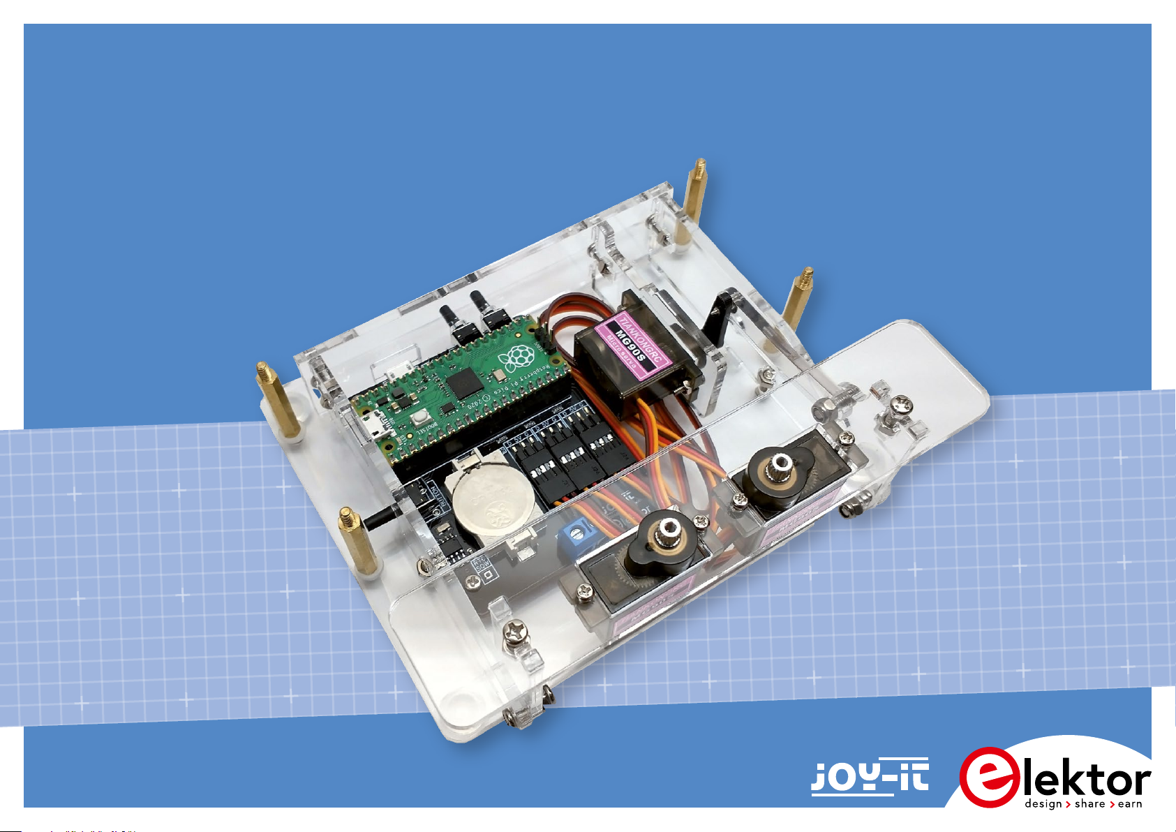
Sand Clock Kit
Assembly Manual
SKU 20679
Page 2

Sand Clock Kit
Assembly Manual
2/16
Version 1.1 - 2024
Sand Clock Kit | Assembly Manual
Page 3
Notice
Assembly
This kit is designed for someone who has intermediate experience with
assembling electronics and mechanics.
If you believe that the kit is too complicated for your skill level please do
not try to assemble it. Take your time - it takes approximately 1 ½-2 hours
to complete this kit.
Ensure your work area is well lit (daylight preferred) and clean.
Assemble the Sand Clock in the order as stated in the instructions - read
and understand each step before you perform each operation.
The following tools and materials will be required to assemble the clock:
• A set of pozidrive screwdrivers or a cordless screwdriver with
pozidrive bits.
• Long nose pliers.
• Tweezers.
• A pencil sharpener.
• A computer with the Arduino IDE installed.
• A micro-USB power supply 5V/1,5A
Assembling and testing the electronics and servos
Step 1
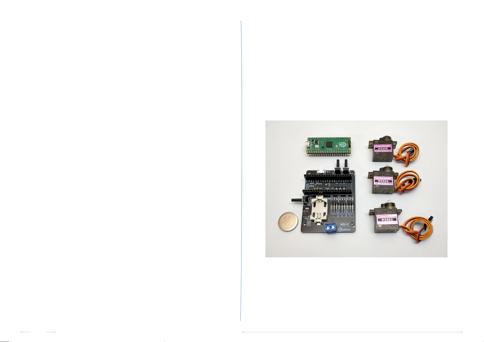
Attach the Raspberry Pi Pico to the baseboard and connect the three
servo motors. The brown wire goes to 'G', the yellow/orange wire goes
to 'D'. Insert the CR2032 3V lithium coin cell to the battery holder on the
baseboard.
In this manual, commands are printed in bold e.g. svml 1800
(Servo move left, 1800 microseconds).
The position of a servo motor corresponds with the pulse width of the
controlling PWM signal and is expressed in microseconds (μs).
Disclaimer: All pictures are for illustration purpose only. Actual product
may vary due to product enhancement.
3/16
Sand Clock Kit | Assembly Manual
Page 4
Step 2
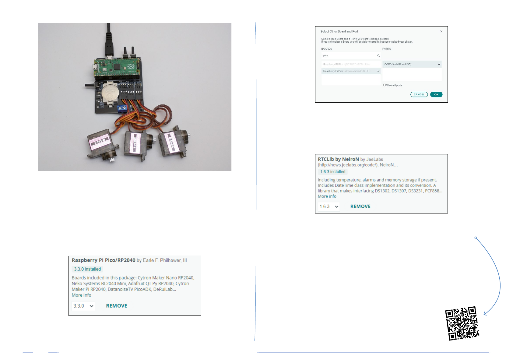
Connect a micro-USB power supply to the baseboard and connect the
Raspberry Pï Pico to your PC with the USB cable included in the kit.
You will have to install the boards package “Raspberry Pi Pico/RP2040
by Earle F. Philhower” in the “boards manager” and select the connected
Raspberry Pi Pico and its port.
https://github.com/earlephilhower/arduino-pico
Install the library “RTCLib by NeiroN by JeeLabs”
https://www.arduino.cc/reference/en/libraries/rtclib-by-neiron/
Download the program for the Sand Clock from the Elektor website
(https://www.elektor.com/20679) and open it in the Arduino IDE.
Compile the program and upload it to the Raspberry Pi Pico.
When the sketch starts up, it first checks if there’s valid calibration data
in the EEPROM. When there’s no valid data, which is the case when the
Raspberry Pi Pico is used for the first time in a Sand Clock, the sketch drives
all three servo motors in the middle position i.e. a pulse width of 1500 μs.
4/16
Sand Clock Kit | Assembly Manual
Page 5
If you wish, you can check the position of the servo motors as follows:
open the serial monitor in the Arduino IDE, select a non-empty character
sequence as line ending (carriage return, newline/linefeed, or both), and
send command svd. The response should indicate all three servo motor
channels have a pulse width of 1500 μs. If not, you can drive the servo
motors in the middle position yourself by sending commands svml 1500,
svmr 1500, and svmp 1500.
Turn o the power, disconnect the servo motors.
Step 3
Mechanical assembly
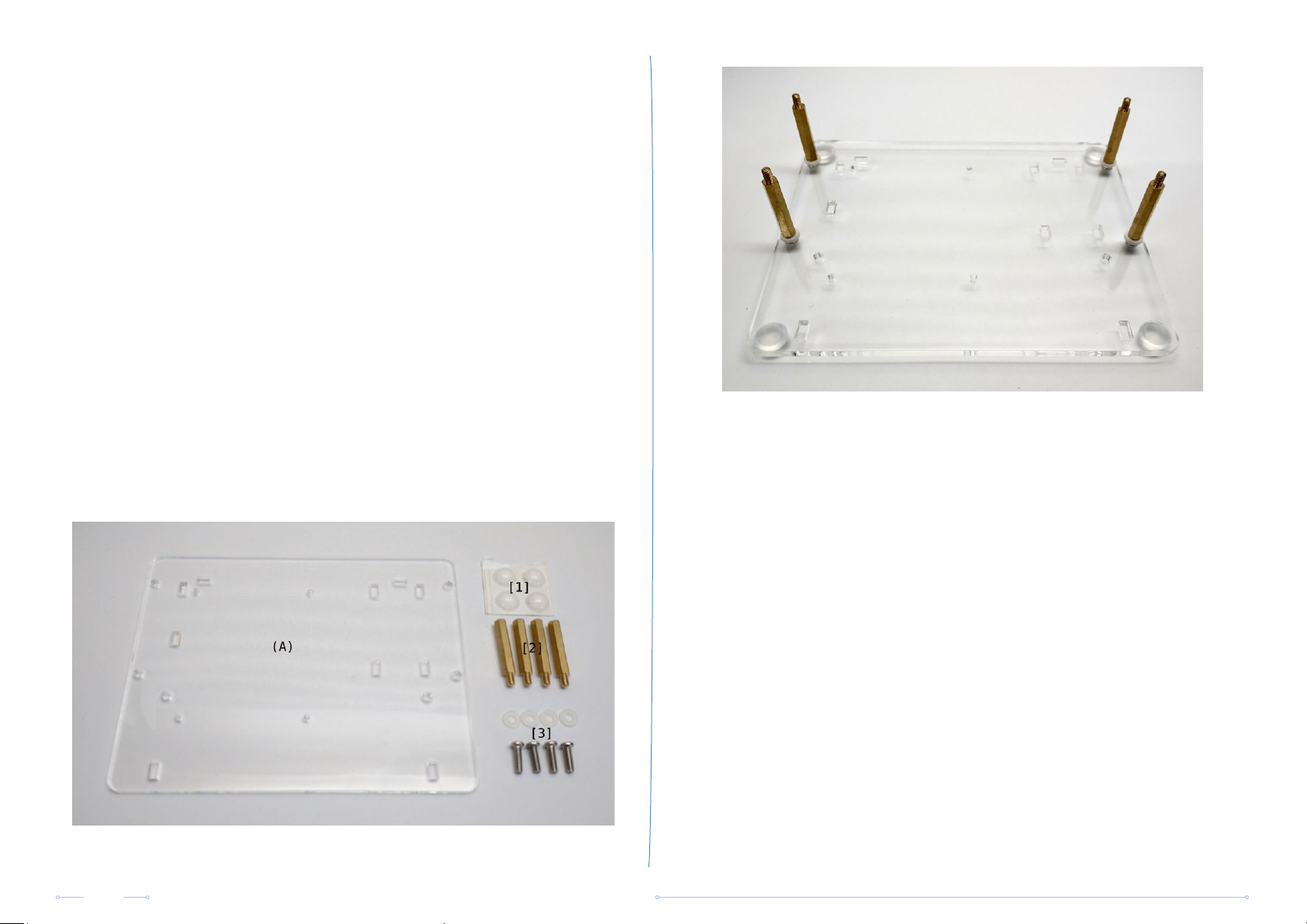
Remove the protective film from both sides of the bottom plate (A)
and stick 4 adhesive rubber bumpers [1] to the corners. Make sure the
orientation of the bottom plate is correct as it is quite diicult to remove
and reposition the rubber bumpers in case of an error.
Mount the 4 standos [2] for the sand box using M3x10 machine
screws[3] and M3 plastic washers [3]. Hand tighten only.
Remove the protective film from both sides of the side panels (B1, B2) and
the rear panel (C) of the frame. Screw the panels together in a right angle
using an M3x10 machine screw [3] and an M3 nut [3].
5/16
Do not over tighten the screws as this may cause the acrylic to break.
Sand Clock Kit | Assembly Manual
Page 6
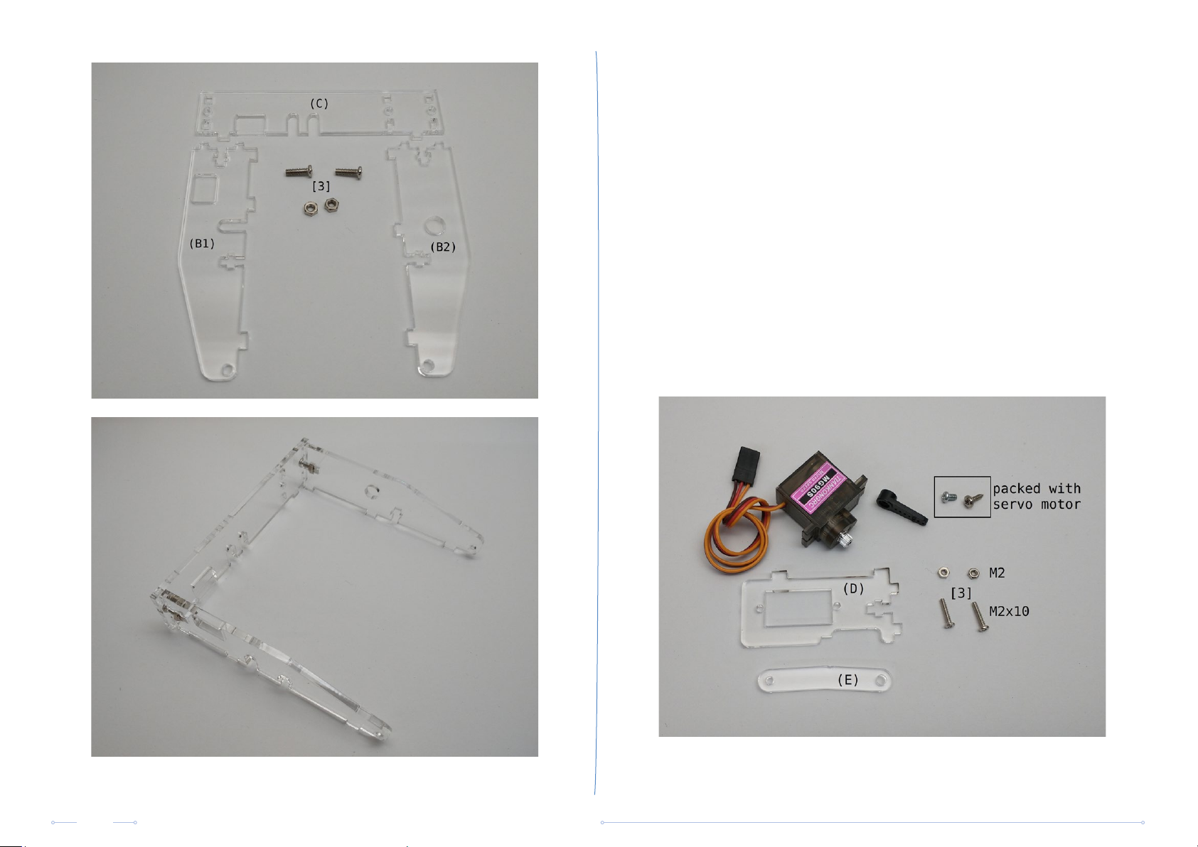
Step 4
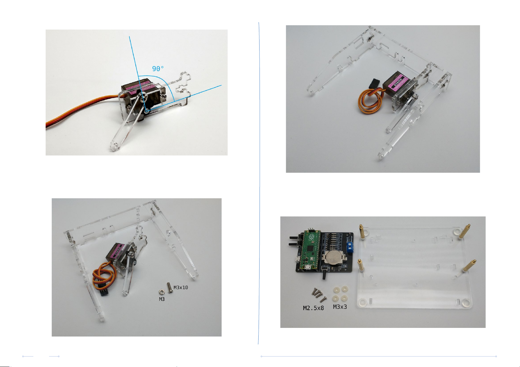
Remove the protective film from both sides of the acrylic parts. Attach
the lift servo to lift servo panel (D) using two M2x10 machine screws [3]
and M2 nuts [3]. Attach the servo arm to the servo shaft using the M2.5
machine screw packed together with the servo accessories.
The servo arm should point more or less upright at an angle of 90
degrees. Don‘t worry if you can‘t get it exactly at 90 degrees due to the
teeth of the servo shaft and the servo arm.
The acrylic lift servo lever (E) has 2 holes. Screw it with the smallest
hole to the servo arm using a self tapping plastic screw from the servo
accessories bag. Tighten the screw so the lever can turn freely with as
little slack as possible. The distance between the center of the servo shaft
and the mounting point of the lever should be +/- 13 mm. This is usually
the second or third last hole in the servo arm.
6/16
Sand Clock Kit | Assembly Manual
Page 7
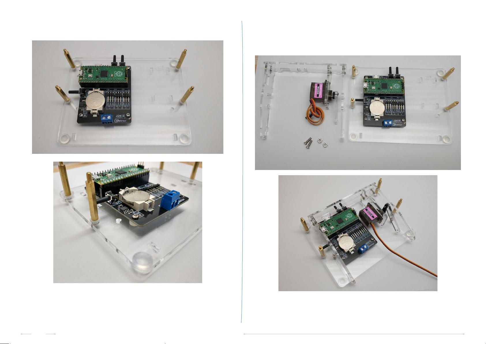
Step 5
Attach the lift servo mechanism to the frame using an M3x10 machine
screw and an M3 nut.
Mount the baseboard to the baseplate using M2.5x8 machine screws and
3 mm plastic spacers. Tighten the screws loosely so the board can still
move a bit.
7/16
Sand Clock Kit | Assembly Manual
Page 8
Note that the screws are tapped into the baseplate, nuts aren‘t required. Now attach the frame with the lift servo mechanism to the baseplate
using two M3x10 machine screws and an M3 nut . Finally tighten the
baseboard mounting screws.
8/16
Sand Clock Kit | Assembly Manual
Page 9
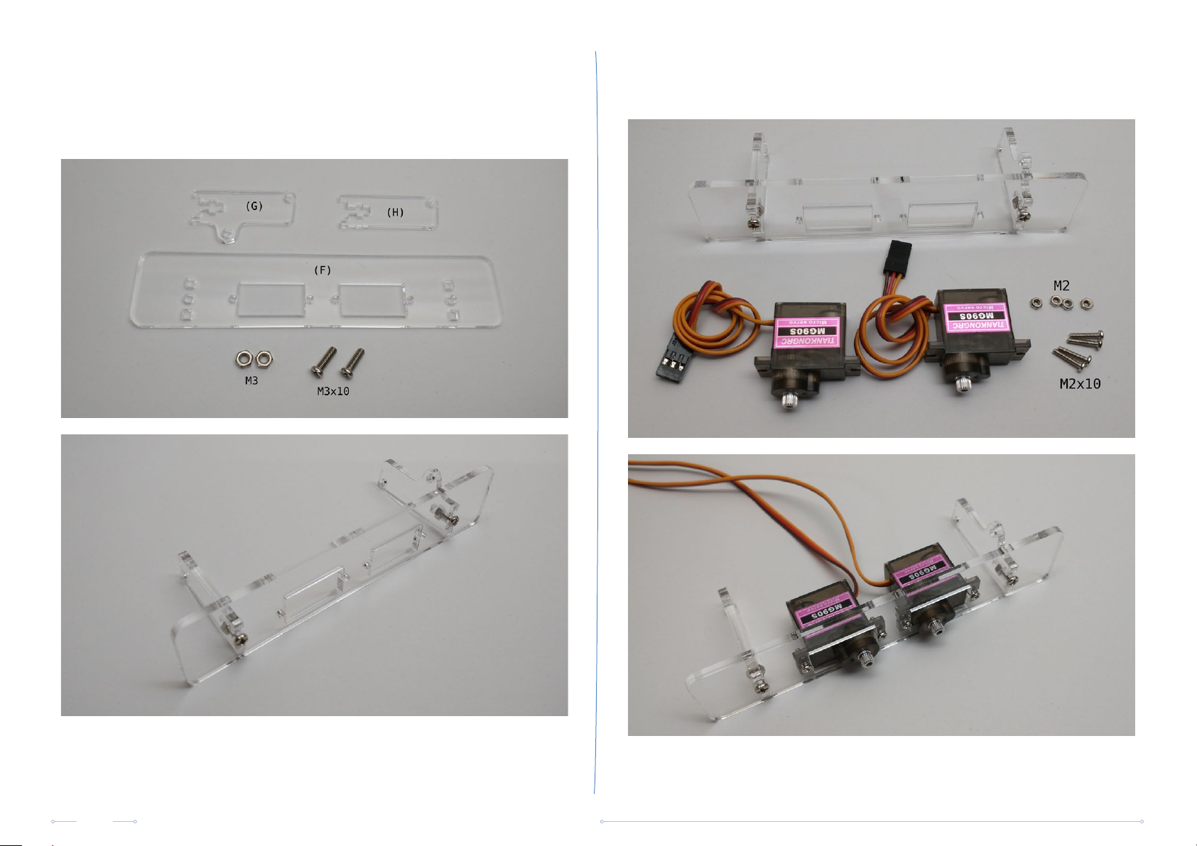
Step 6
Remove the protective film from both sides of the acrylic parts (F), (G)
and (H). Attach the hinges (H) and (G) to the pantograph servo motors
mounting plate (F) using M3x10 machine screws and M3 nuts.
Mount both servo motors using M2x10 machine screws and M2 nuts.
9/16
Sand Clock Kit | Assembly Manual
Page 10
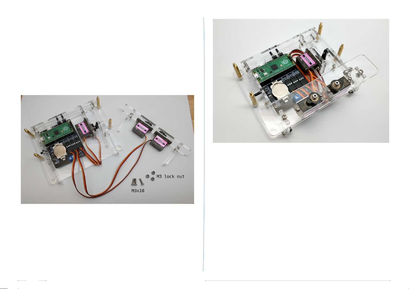
Step 7
Attach the pantograph servo mechanism to the base of the clock using
2 M3x10 machine screws and 2 M3 lock nuts. Tighten the screws so the
pantograph mechanism can rotate freely with as little slack as possible.
Route the servo wires under the lift servo and connect them to the
baseboard. Respect their polarity. Turn the pantograph servo mechanism
upright and attach it to the lift servo lever using an M3x10 machine screw
and a M3 lock nut. Tighten so the mechanism can operate freely with as
little slack as possible.
Step 8
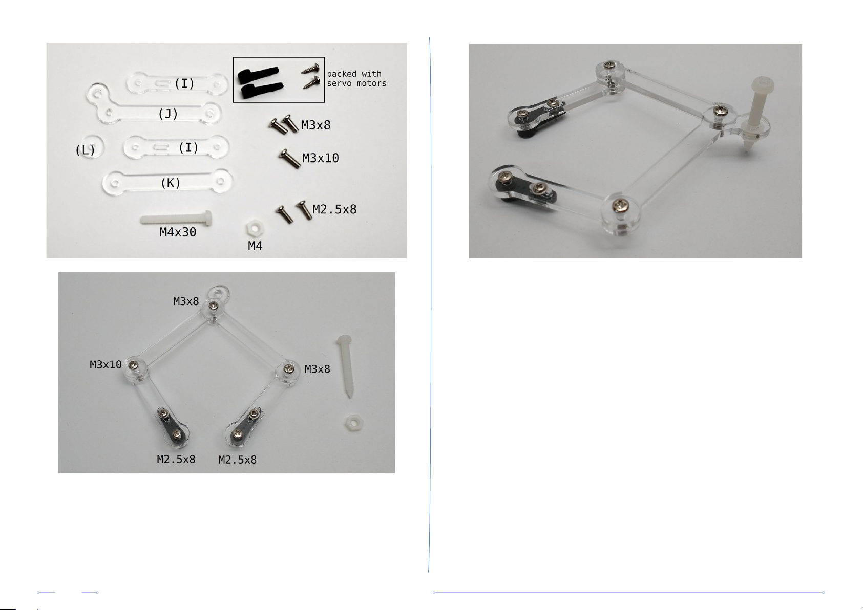
Remove the protective film from both sides of the acrylic parts (I), (J), (K)
and (L). Assemble the pantograph arms. Screw part (J) on top of one of
the parts (I) using an M3x8 machine screw. Then screw part (K) on top of
part (J) using an M3x8 machine screw. Finally screw the other side of part
(K) on top of the second part (I) with the round acrylic disc (L) in between
using an M3x10 machine screw. Make sure the orientation of part (J) is as
shown in the photo.
10/16
Tighten the screws so the arms can rotate freely with as little slack as
possible. Be gentle and do not use excessive force as the acrylic may
break. Finish the assembly of the pantograph arms by attaching the servo
arms. Temporarily fit an M2.5x8 machine screw through the holes in the
acrylic and the servo horns. Then secure the servo arms to the acrylic
arms (I) using 2 plastic screws supplied with the servo motors.
Carefully sharpen the plastic M4x30 machine screw with a pencil
sharpener and fit it together with an M4 nut to the pantograph assembly.
Sand Clock Kit | Assembly Manual
Page 11
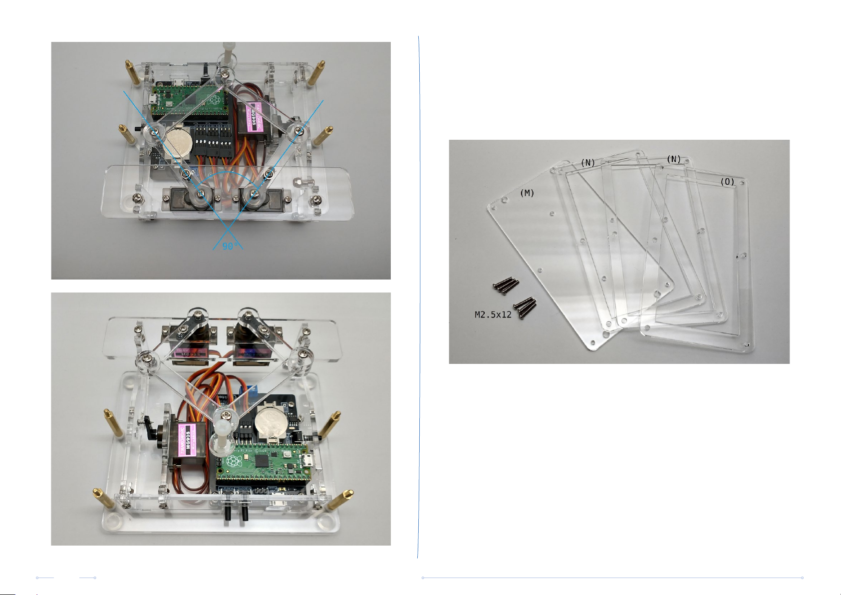
Attach the pantograph mechanism to the pantograph servo motors using
the M2.5x8 machine screws. Mount the arms so they form an angle of 90
degrees. Don‘t worry if you can‘t position them exactly to 90 degrees due
to the teeth on the servo motor shafts and the servo arms. This will be
compensated after calibration.
11/16
Sand Clock Kit | Assembly Manual
Page 12
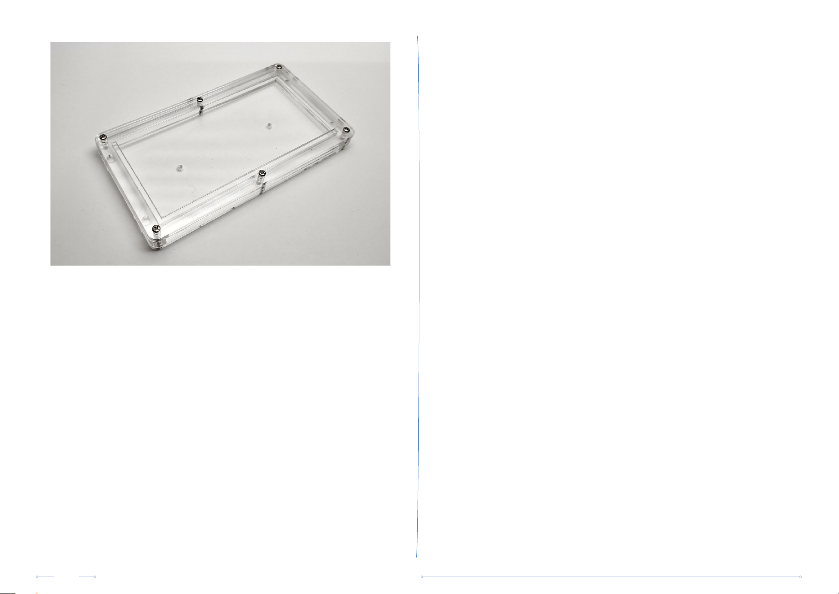
Step 9
Remove the protective film from both sides of the acrylic parts of the
sandbox (M), (N) and (O). The part with the widest rim (O) goes on top.
Screw the panels together using 6 M2.5x12 machine screws. Make sure
the panels are secured firmly against each other without over tightening
the screws.
12/16
Sand Clock Kit | Assembly Manual
Page 13
Calibration steps:
• Move the left servo motor to its vertical position (towards 1000 μs),
e.g. svml 1080. Send this command with various values until you’ve
determined the most accurate position.
• Store the setting: svslv.
• Move the right servo motor to its vertical position (towards 2000 μs),
e.g. svmr 2050. Send this command with various values until you’ve
determined the most accurate position.
• Store the setting: svsrv.
• Move the left servo motor to its horizontal position (towards 2000 μs),
e.g. svml 1940. Send this command with various values until you’ve
determined the most accurate position.
Step 10
Calibration procedure
The calibration procedure involves sending commands to the clock.
Connect a micro-USB power supply to the baseboard and connect
the Raspberry Pi Pico to the computer with the included USB cable.
All servos should now be at 1500 μs (this may not be the case if you‘ve
written settings to the EEPROM before).
Open the serial port using Arduino IDE‘s Serial Monitor. Select a
non-empty character sequence as line ending (carriage return, newline/
linefeed, or both). Now you‘re set up to send commands.
During the procedure you can always query the current settings and the
position of the servo motors by sending command sed and command
svd respectively.
13/16
Sand Clock Kit | Assembly Manual
• Store the setting: svslh.
• Move the left servo motor back to its vertical position using svml with
the value previously determined earlier. You can query the correct
value using sed.
• Move the right servo motor to its horizontal position (towards 1000 μs),
e.g. svmr 1080. Send this command with various values until you’ve
determined the most accurate position.
• Store the setting: svsrh.
• Move pen up: svmp 2000.
• Set pen position: ps 0 40.
• Place the partially finished sandbox on the standos and make sure
it lies perfectly flat on all 4 standos. In case the sand box wiggles on
the standos, twist it slightly diagonally until it lies perfectly flat.
Page 14

• Move the pen servo motor to the down position (towards 1500 μs),
e.g. svmp 1525. Send this command with various values until you’ve
determined the most accurate position. The clock moves to pen to
the down position when it wants to write something in the sand. The
pantograph arms should be perfectly horizontal and the tip of the
pen should hover approximately 1 – 2 mm above the bottom of the
sandbox. If necessary, mechanically adjust the pen by screwing it up
or down. Use the M4 nut to lock it in place.
• Store the setting: svspd.
• Set the vibration period (seconds), e.g. vms 5.
• Review the settings with sed. Modify settings if needed. Note that
start-up program mode should be set to command. Don’t change the
mode at this point.
• Store settings in EEPROM: sew.
• Set date and time in realtime clock, e.g. cw 2024 08 27 18 40 00. Note
that a CR2032 battery must be installed.
• Check the pen down position in relation to the sandbox:
• Pen position 1: ps 0 30.
• Pen position 2: ps 0 55.
• Adjust the pen servo motor if needed.
• Set the pen in a neutral position: ps 0 40.
• Move the pen servo motor to the middle position (towards 1800 μs),
e.g. svmp 1700. Send this command with various values until you’ve
determined the most accurate position. The clock moves the pen to
the middle position when it needs to move the pen above the sand
between continuous strokes.
• Store the setting: svspm.
• Move the pen servo motor to the top position (towards 2100 μs), e.g.
svmp 2150. Send this command with various values until you’ve
determined the most accurate position. Your goal is to move the pen
to highest position possible (servo horn in line with the acrylic lever).
The clock moves the pen to the top position when it’s not writing the
time.
• Check date and time with cr.
• Lift pen up with plu.
• Power o the sand clock.
Step 11
Mount the plastic clips on the bottom side of the sandbox using 2 M3x6
machine screws and 2 M3 steel washers. Do not tighten the screws
completely yet.
Slide the vibration motors in the clips and position them as shown in the
picture below.
• Store the setting: svspu.
14/16
Sand Clock Kit | Assembly Manual
Page 15
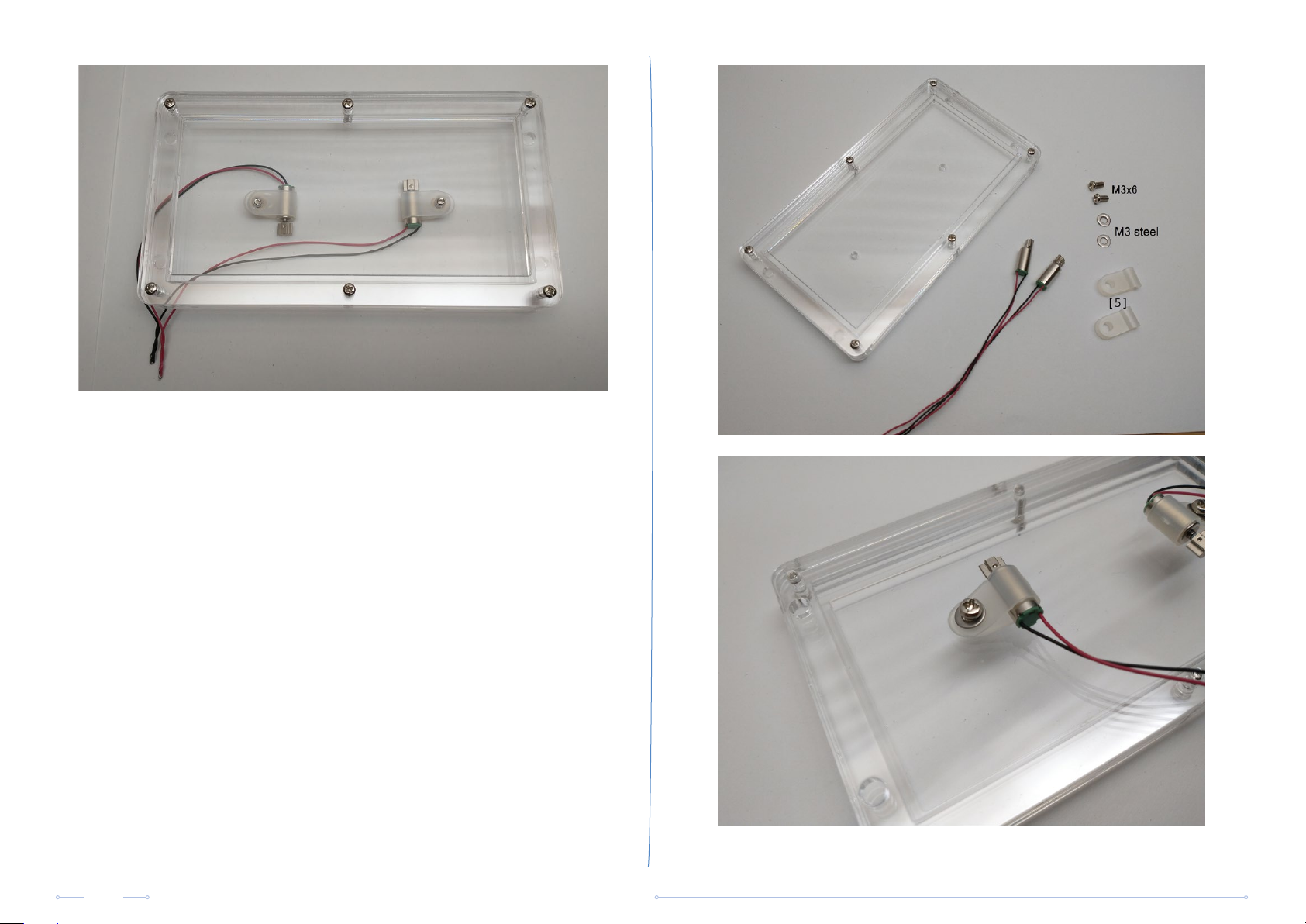
Now tighten the screws until the vibration motors are firmly in place and
the clips cannot rotate easily anymore. You can try dierent alignments of
the vibration motors to discover how it eects the distribution of the sand
while vibrating.
15/16
Sand Clock Kit | Assembly Manual
Page 16
Step 12
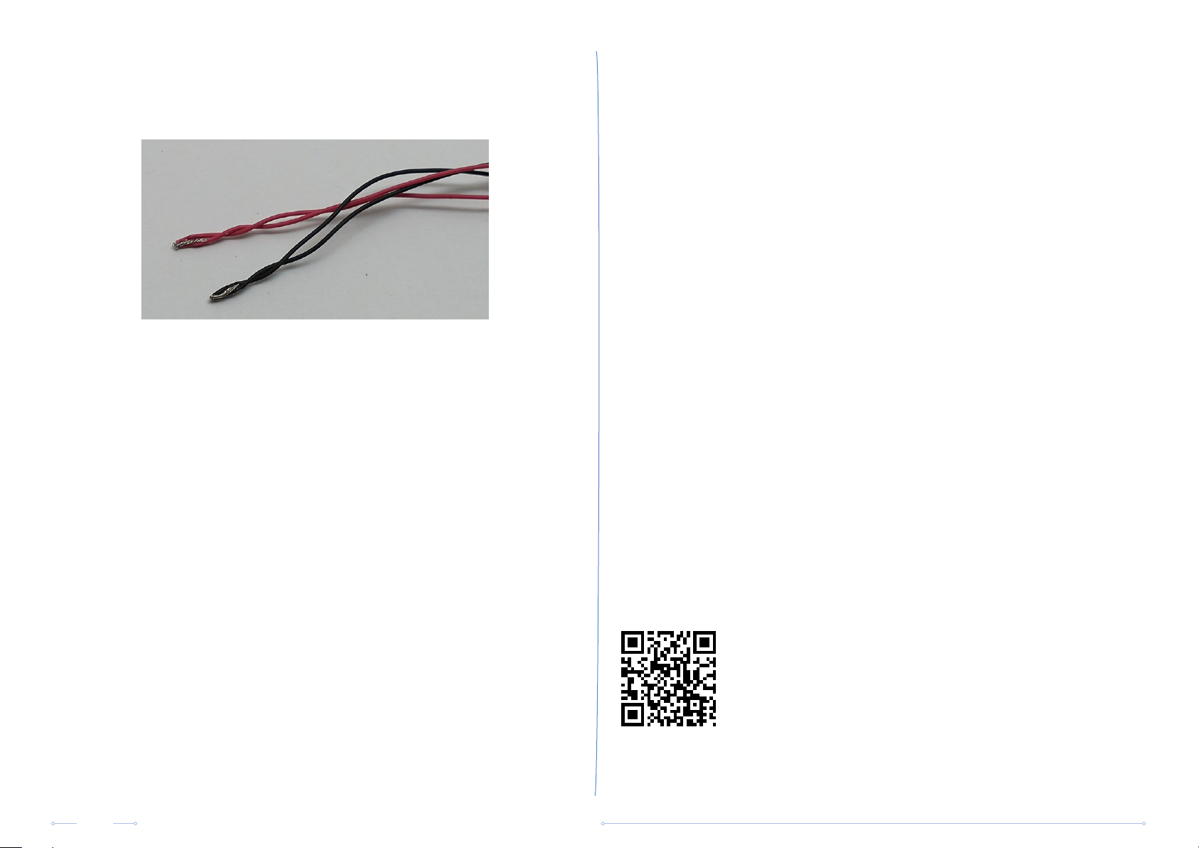
Connect the wires of the vibration motors together and attach them to the
connector on the baseboard. Check the polarity.
Place the sandbox on top of the standos and make sure wires are not
touching the rotating parts of the vibration motors. Rearrange wires if
necessary. Test the clock without sand to make sure everything works
well.
Step 14
Final calibration
Power on the Sand Clock again. The device starts up in command mode.
Calibrate the pen further if necessary. The following commands draw an
“8” in the sand:
ps -10 25
pg 8 1 1
Select the start-up mode. This is the mode that takes eect every time
you power up or reset the clock.
Send command msa for autonomous mode (normal clock
behavior) or msc for command mode (use serial monitor to
control the device).
Step 13
Add the sand to the sandbox. A layer of 4 – 5 mm will be suicient, be
sure to spread it out evenly.
If you wish you can also color the sand using food coloring. Put the sand
in a small jar and add a few drops of food coloring. Shake vigorously until
the sand gets evenly colored.
Repeat until you get the desired color intensity. Make sure the sand has
dried completely before you pour it in the sandbox.
16/16
Sand Clock Kit | Assembly Manual
Send command sew to program the selected start-up mode and
other settings into EEPROM.
Send command ma if you want to immediately switch from
command mode to autonomous mode.
Congratulations, your Sand Clock is now finished
For more information and software downloads:
www.elektor.com
www.joy-it.net
 Loading...