

Page 1
Joy-IT powered by SIMAC Electronics GmbH - Pascalstr. 8 - 47506 Neukirchen-Vluyn - www.joy-it.net
Page 2

TABLE OF CONTENTS
1. General information .........................................................................................................................................................3
2. Device overview & pin assignment .................................................................................................................................. 3
3. Raspberry Pi Pico .............................................................................................................................................................5
4. Modules in detail ..............................................................................................................................................................7
4.1 Buzzer .............................................................................................................................................................................7
4.2 RGB LEDs .........................................................................................................................................................................8
4.3 Relay ................................................................................................................................................................................ 9
4.4 TFT ................................................................................................................................................................................10
4.5 DHT11 ...........................................................................................................................................................................11
4.6 Buttons ..........................................................................................................................................................................12
4.7 Servos ...........................................................................................................................................................................13
4.8 Interfaces ......................................................................................................................................................................14
4.9 Breadboard ................................................................................................................................................................... 15
5. Information & take-back obligations ............................................................................................................................. 16
6. Support ...........................................................................................................................................................................17
Page 3

. GENERAL INFORMATION
Dear customer, thank you for choosing our product. In the following, we will show you what you need to bear in mind during commissioning and use.
Should you encounter any unexpected problems during use, please do not hesitate to contact us.
These instructions were written under Micropython version 1.22.2.
. DEVICE OVERVIEW & PIN ASSIGNMENT
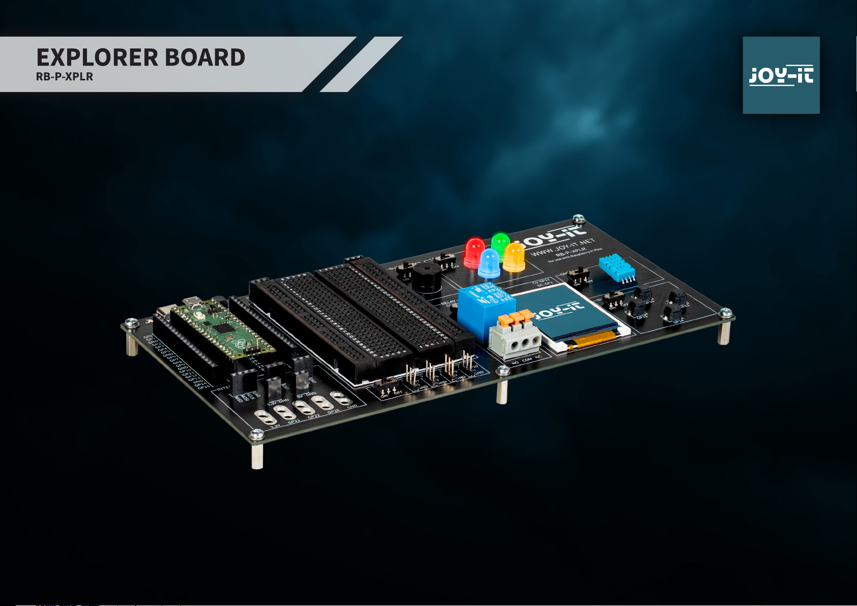
Our Explorer Board is the simple and eicient way to develop your Raspberry Pi Pico projects.
With the most important components already integrated, you save time and eort when wiring. The Explorer Board has a wide range of interface connectors,
so you can connect your projects to a variety of modules and devices. With the integrated breadboard, you can quickly build and realize your own projects.
Thanks to the option of switching all modules on or o individually, you can use your pins, which are also routed separately to the outside, for other projects
or experiment on the integrated breadboard at any time.
All built-in components can be switched o via the respective switch if they are not required. This means that the associated pins can also be used for other
components if necessary.
To the le and right of the Raspberry Pi Pico, all pins are additionally designed. Components can be connected directly here or routed to the integrated
breadboard via additional cables.
3
Page 4
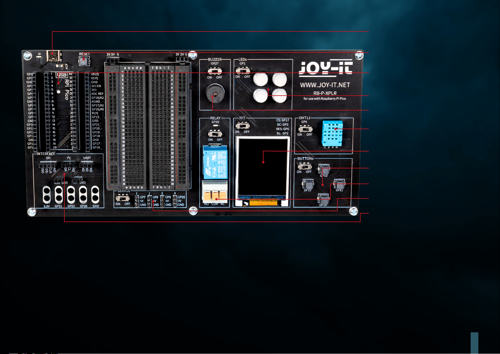
5 V USB-C power supply
Reset Button
Slot
Raspberry Pi Pico
4x RGB LED
Buzzer
DHT11 Temperature & humidity sensor
1,8" TFT Display
4x Buttons
Relay
4x Servo-Interface
Interface connections
4
Page 5

PIN ASSIGNMENT
Buzzer
LEDs
Relay
1,8" TFT Display
DHT11
Buttons
Servos
UART
I2C
SPI
GP27
GP1
GP28
CS: GP17, DC: GP3, RES: GP6, BL: GP2
GP0
GP10, GP11, GP14 & GP15
GP7, GP8, GP9 & GP20
RXD: GP13, TXD: GP12
SDA: GP4, SCL: GP5
MISO: GP16, MOSI: GP19, SCLK: GP18
5
Page 6
. RASPBERRY PI PICO
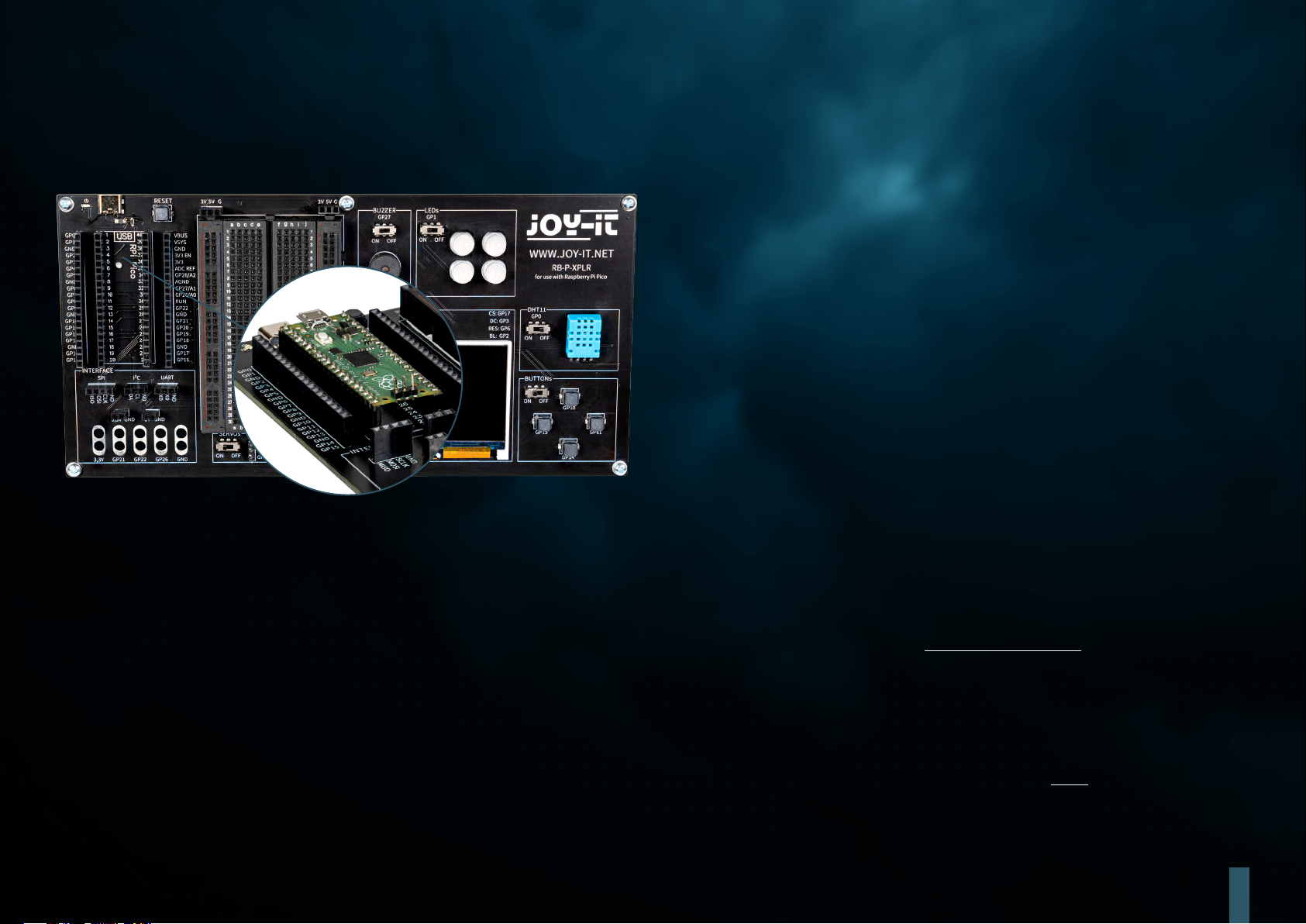
First plug your Raspberry Pi Pico into the slot on your board.
Now connect a micro USB cable to your computer and to the Raspberry Pi Pico for programming.
ATTENTION! The USB-C port on the Explorer board is used exclusively for power supply. It is not used to transfer data to the Raspberry Pi.
You can use a suitable development program of your choice to transfer our sample program. We recommend the Thonny Python IDE.
ATTENTION! If you are new to the world of microcontrollers and electronics, don't worry! We have prepared a special beginner's guide for you. This guide is
specially tailored to the needs of beginners and explains how to use the Raspberry Pi Pico step by step.
From basic configuration to running projects, this guide will walk you through the entire process. Our guide includes easy-to-understand explanations and
useful tips to help you quickly and eectively develop your skills at scale with the Raspberry Pi Pico. You can download our guide here.
6
Page 7
. MODULES IN DETAIL
In the following, all modules available on the Explorer Board are explained individually with sample codes. You can download all sample codes and libraries
here, as well as a sample code that links all modules together.
External libraries and a font file are used for the use of some modules. Download the libraries and load them into the lib folder of your Raspberry Pi Pico.
Place the font file in the root directory of your Raspberry Pi Pico.
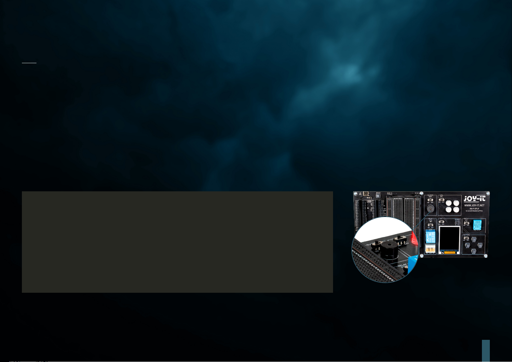
. BUZZER
A buzzer produces a signal tone, similar to a loudspeaker. Unlike a loudspeaker, however, it is only suitable for a limited frequency range, so it does not
produce a good sound for reproducing music or speech. However, it is ideal for generating loud warning tones in the form of beeps. Whenever an electrical
device generates a warning tone, it is almost always a buzzer. For example, in alarm clocks, smoke detectors or the seatbelt reminder in cars.
The buzzer is connected to GPIO pin GP27.
# Load libraries
from machine import Pin, PWM
from utime import sleep
buzzerPin = Pin(27)
buzzer = PWM(buzzerPin)
while True:
# Activate buzzer for 1 sec
buzzer.freq(1000)
buzzer.duty_u16(1000)
sleep(1)
buzzer.duty_u16(0)
sleep(1)
7
Page 8
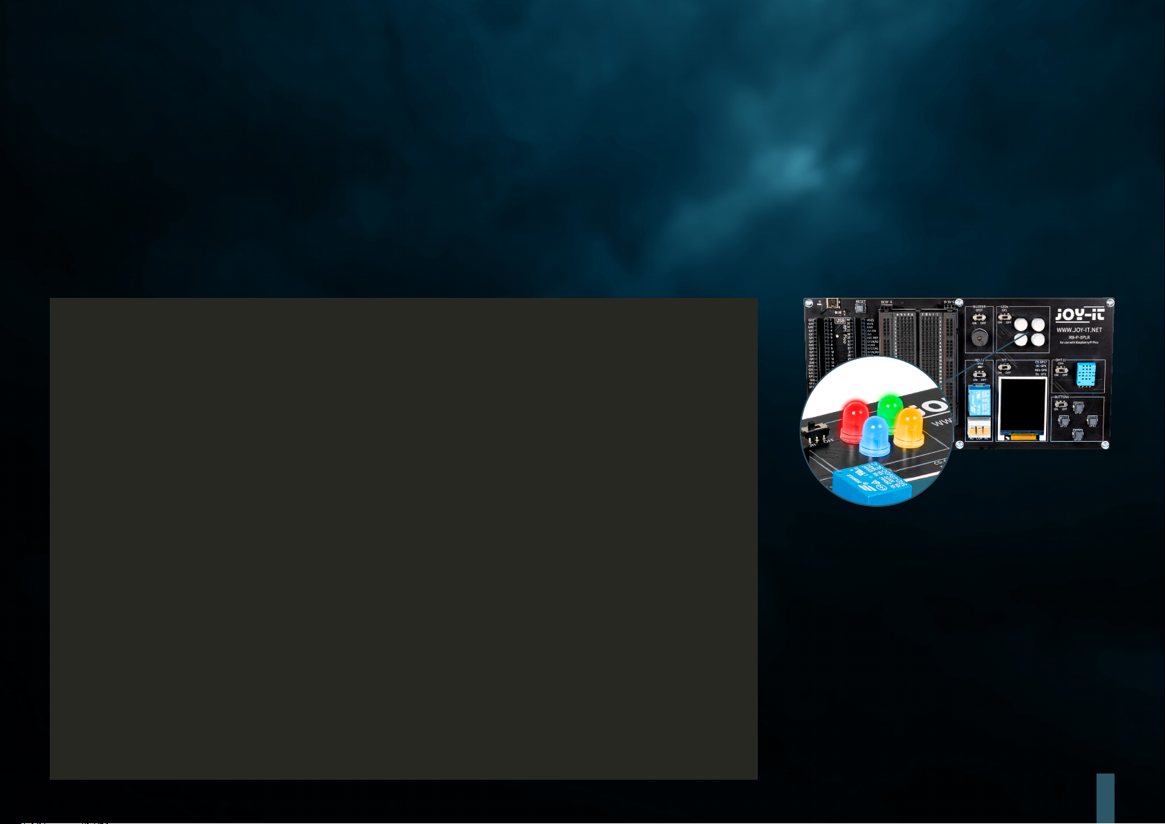
. RGB LEDS
RGB LEDs are a type of light-emitting diode that combines red, green and blue to produce a variety of colors. Much like a buzzer only produces simple
tones, RGB LEDs cannot display complex images, but they are excellent at mixing and varying colors. Each LED in an RGB unit can be varied in intensity to
produce dierent hues, from so pastels to bright, saturated colors. This makes them ideal for mood lighting, decorative lighting and in applications where
visual signals are required, such as in gaming setups or as status indicators in electronic devices. Their versatility and energy eiciency have made them a
popular choice in modern lighting systems, although, like the buzzer, their simple operation means they cannot create complex images or patterns without
additional control units.
The GPIO LEDs are connected to the GPIO pin GP1.
# Load libraries
from machine import Pin, PWM
from utime import sleep
from neopixel import NeoPixel
ledPin = 1
ledCount = 4
# Initialize GPIOs
led = Pin(ledPin, Pin.OUT)
led = NeoPixel(Pin(ledPin, Pin.OUT), ledCount)
while True:
# Turn LEDs white
for i in range (ledCount):
led[i] = (255, 255, 255)
led.write()
sleep(1)
# Turn LEDs red
for i in range (ledCount):
led[i] = (255, 0, 0)
led.write()
sleep(1)
# Turn LEDs blue
for i in range (ledCount):
led[i] = (0, 0, 255)
led.write()
sleep(1)
# Turn LEDs green
for i in range (ledCount):
led[i] = (0, 255, 0)
led.write()
sleep(1)
8
Page 9
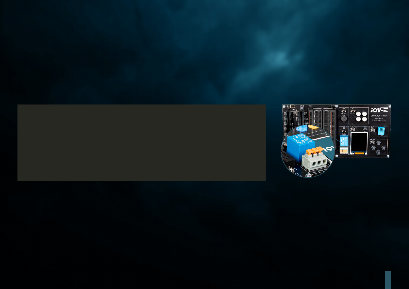
. RELAY
Relays are some of the oldest electromechanical components and function as electrically controlled switches. With a small input voltage and low current, a
large electrical load can be switched on and o at the output. When the relay switches through, the red LED also lights up. You can insert stripped cable ends
into the terminal socket (by pressing down the orange lever) to use the three connections.
The relay is connected to GPIO pin GP28.
# Load libraries
from machine import Pin, PWM
from utime import sleep
relayPin = 28
# Initialize GPIOs
relay = Pin(relayPin, Pin.OUT)
while True:
# Toggle Relay
relay.on()
sleep(1)
relay.off()
sleep(1)
Caution! Work on electrical systems with voltages above 60 V may only be carried out by qualified
electricians. Persons without appropriate training are strongly recommended to switch only the low
voltages 3 & 5 V available on the board using the relay. Improper handling can lead to serious injury or
even death due to heat, fire or electric shock.
Please observe the safety regulations and consult a specialist if you are unsure.
9
Page 10
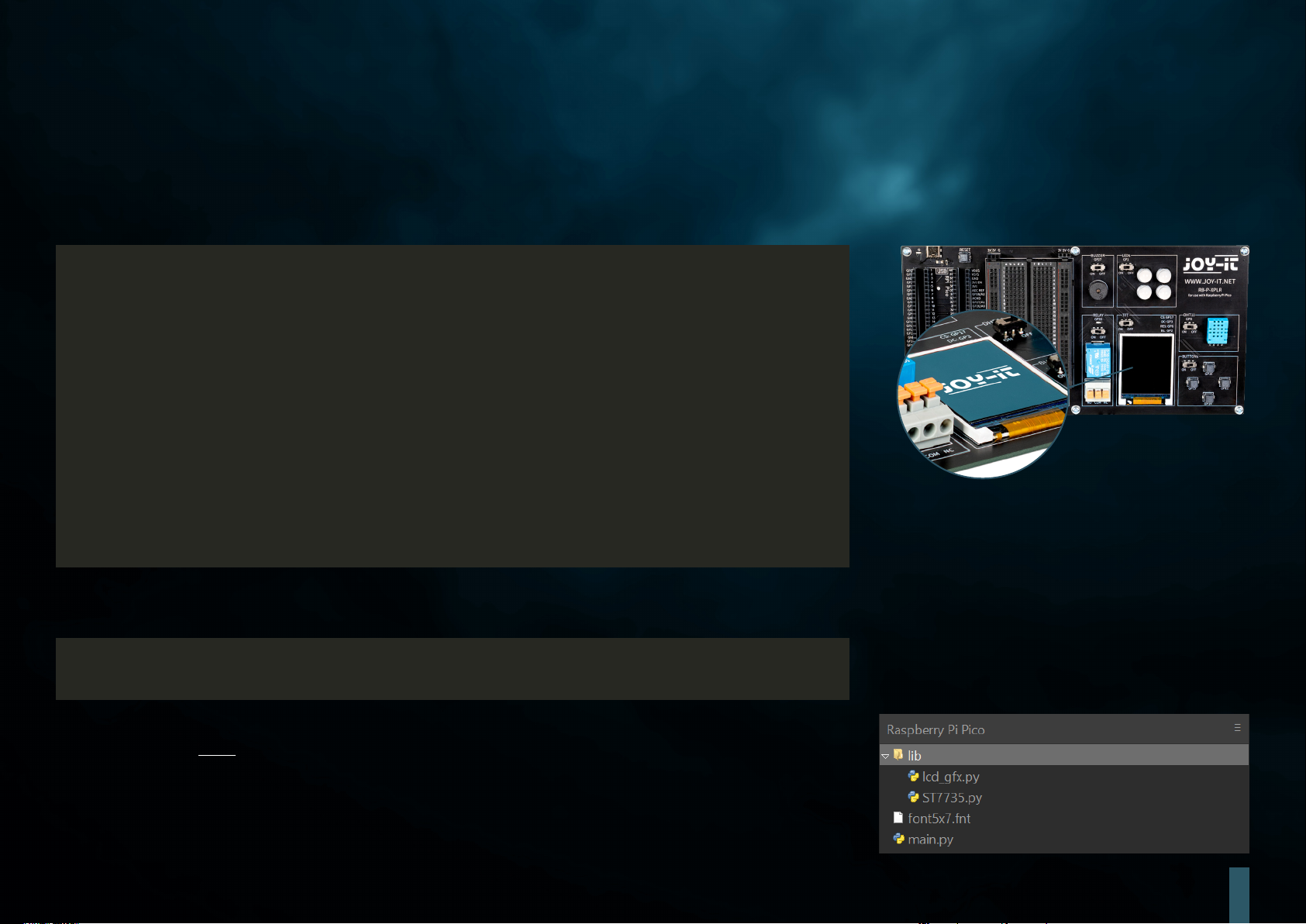
. TFT
The liquid crystal display (LCD TFT) with around 65,000 colors and a diagonal of 1.8 inches has a resolution of 128×160 pixels and can be controlled via SPI.
It is suitable for displaying colorful graphics and images. Letters and other characters are displayed as graphics made up of many individual dots.
The TFT is connected to the GPIO pins GP17 (CS), GP3 (DC), GP6 (RES) and GP2 (BL).
from machine import Pin, SPI
import ST7735
# Initialize LCD
spi = SPI(0, baudrate=8000000, polarity=0, phase=0, sck=Pin(18), mosi=Pin(19),
miso=Pin(16))
lcd = ST7735.ST7735(spi, rst=6, ce=17, dc=3)
backlight = Pin(2, Pin.OUT)
# Turn backlight on
backlight.high()
lcd.reset()
lcd.begin()
# Display content on the LCD
lcd.ll_screen(lcd.rgb_to_565(0, 255, 0)) # Fills the screen with a green color
# Display text
lcd.p_string(20, 50, "Hello, World!")
In addition to texts, rectangles can also be displayed, for example:
# Draw red rectangle
lcd.draw_block(10, 10, 50, 50, lcd.rgb_to_565(255, 0, 0))
ATTENTION! Two separate library files and a font file are required for the TFT display; you can download
the required files here. Then transfer all files from the Libraries folder to the root directory of your
Raspberry Pi Pico so that the folder structure looks like this:
10
Page 11
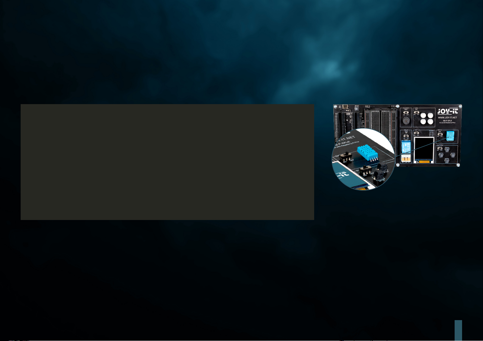
. DHT
The DHT11 sensor can detect temperatures from 0 °C to 50 °C (±2 °C accuracy) and relative humidity from 20 % to 80 % (±5 %) (at most once per second).
Weather stations are probably the primary area of application for a sensor such as the DHT11. To test the functionality, it is suicient to hold your mouth
close to the sensor and exhale slowly. The breathing air diers from the environment in terms of temperature and humidity, which should lead to a significant
change in the values.
The DHT11 is connected to the GPIO pin GP0.
from machine import Pin
from dht import DHT11
from utime import sleep
# Initialize DHT11 Sensor
dhtPin = 0
dht = DHT11(Pin(dhtPin, Pin.IN))
while True:
# Measure DHT11 values
dht.measure()
temp = dht.temperature() # Temperature in Celsius
humid = dht.humidity() # Relative Humidity in %
# Print the measurements
print('Temperature:', temp, '°C')
print('Humidity:', humid, '%')
sleep(2) # Wait for 2 seconds before the next reading
11
Page 12
. BUTTONS
Buttons are interactive elements in user interfaces that fulfill a simple but essential function: user input. Similar to how RGB LEDs can display a variety of
colors, buttons are used to initiate a wide range of commands and actions in digital environments.
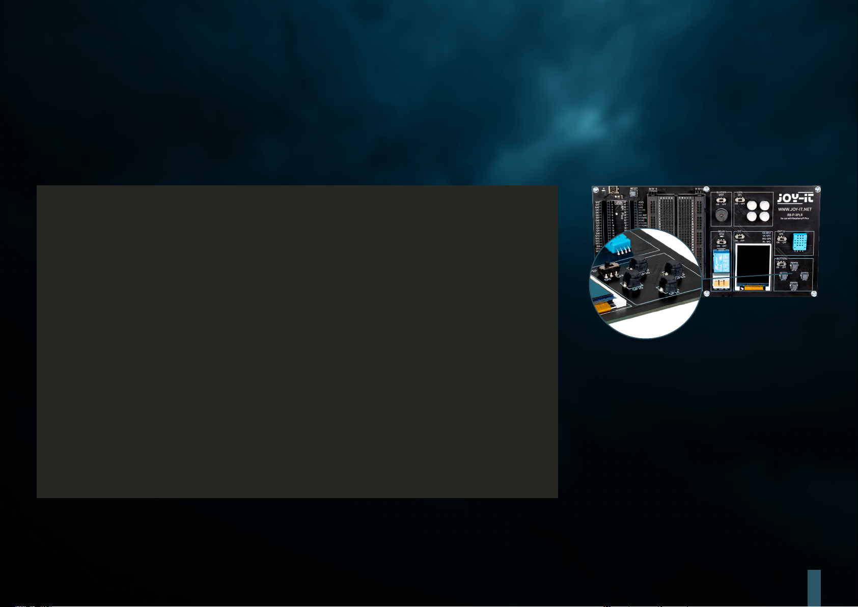
The buttons are connected to the GPIO pins GP10 (top), GP11 (right), GP14 (bottom) and GP15 (le).
from machine import Pin
# Dene button pins
buttons = [10, 11, 14, 15]
# Initialize buttons
buttonOne = Pin(buttons[0], Pin.IN, Pin.PULL_DOWN)
buttonTwo = Pin(buttons[1], Pin.IN, Pin.PULL_DOWN)
buttonThree = Pin(buttons[2], Pin.IN, Pin.PULL_DOWN)
buttonFour = Pin(buttons[3], Pin.IN, Pin.PULL_DOWN)
# Dene button handler functions
def buttonUp(pin):
print("Button Up Pressed")
def buttonRight(pin):
print("Button Right Pressed")
def buttonDown(pin):
print("Button Down Pressed")
def buttonLeft(pin):
print("Button Left Pressed")
# Attach interrupt handlers to buttons
buttonOne.irq(trigger=Pin.IRQ_RISING, handler=buttonUp)
buttonTwo.irq(trigger=Pin.IRQ_RISING, handler=buttonRight)
buttonThree.irq(trigger=Pin.IRQ_RISING, handler=buttonDown)
buttonFour.irq(trigger=Pin.IRQ_RISING, handler=buttonLeft)
12
Page 13
. SERVOS
A servo consists of an electric motor with gearbox and control electronics. On the output side of the gearbox there is a gear wheel on which the servo horn
is mounted. The servo can move the axis in a range of around 180°. Servos are used in model making, for example to control the wing or rudder position of
an airplane or ship. More and more servos are also being used in automotive engineering to automatically close doors, for window regulators, mirrors and
other adjustable elements.
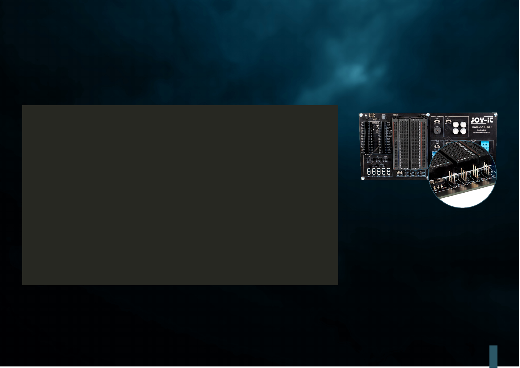
The servo connections are the GPIO pins GP7, GP8, GP9 and GP20.
from machine import Pin, PWM
from utime import sleep
# Servo pin numbers
servoOnePin = 7
servoTwoPin = 8
servoThreePin = 9
servoFourPin = 20
# Initialize servos
servoOne = PWM(Pin(servoOnePin))
servoTwo = PWM(Pin(servoTwoPin))
servoThree = PWM(Pin(servoThreePin))
servoFour = PWM(Pin(servoFourPin))
# Set PWM frequency to 50 Hz for all servos
servoOne.freq(50)
servoTwo.freq(50)
servoThree.freq(50)
servoFour.freq(50)
# Servo degree positions in nanoseconds
deg0 = 500000 # 0.5 ms
deg45 = 1000000 # 1.0 ms
deg90 = 1500000 # 1.5 ms
deg135 = 2000000 # 2.0 ms
deg180 = 2500000 # 2.5 ms
13
Page 14
while True:
# Move each servo through a range of angles
for servo in [servoOne, servoTwo, servoThree, servoFour]:
print("Moving to 0 degrees")
servo.duty_ns(deg0)
sleep(1)
print("Moving to 45 degrees")
servo.duty_ns(deg45)
sleep(1)
print("Moving to 90 degrees")
servo.duty_ns(deg90)
sleep(1)
print("Moving to 135 degrees")
servo.duty_ns(deg135)
sleep(1)
print("Moving to 180 degrees")
servo.duty_ns(deg180)
sleep(1)
14
Page 15
. INTERFACES
Interface connections play a crucial role in the world of electronics, similar to buttons in user interfaces.
They enable communication and power supply between dierent electronic components. The following
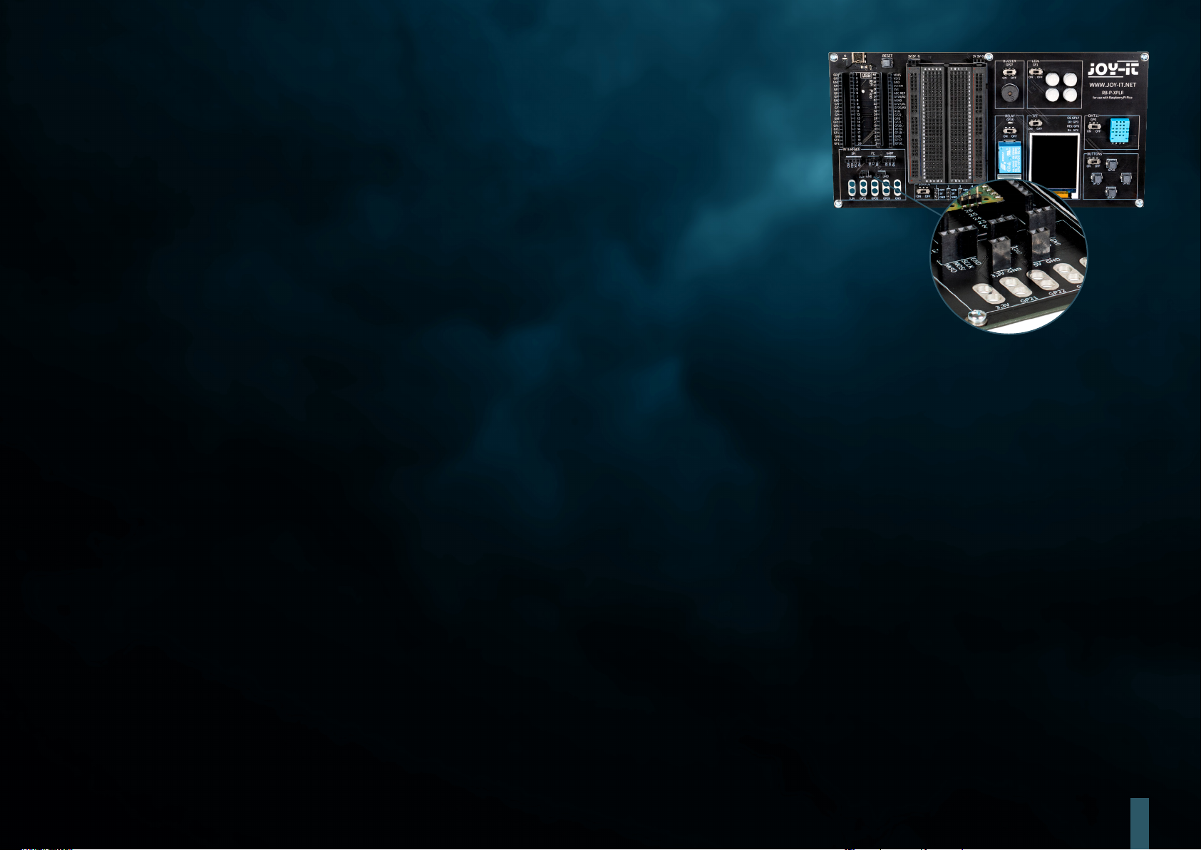
connections can therefore be found in the interface area on our Explorer Board:
SPI (Serial Perhipheral Interface): This connection is used for fast serial data transmission. It typically
consists of four lines: MISO (Master In, Slave Out), MOSI (Master Out, Slave In), SCK (Serial Clock) and SS
(Slave Select). SPI is ideal for situations where a high data transfer rate is required, such as when controlling
LCD displays or SD cards.
I2C (Inter-Integrated Circuit): I2C is a two-wire interface consisting of a data line (SDA) and a clock line
(SCL). It is commonly used in microcontroller applications for communication between dierent integrated
circuits. Its simplicity makes it ideal for applications where not many GPIO pins are available.
UART (Universal Asynchronous Receiver/Transmitter): This interface enables asynchronous serial communication via two lines: TX (Transmit) and RX
(Receive). UART is oen used for communication between microcontrollers and computers or for connecting modules such as GPS receivers or Bluetooth
modules.
3.3 V and 5 V connections: These connections provide the power supply for electronic components. 3.3 V is oen used for modern microcontrollers and
sensors, while 5 V is oen found in older or more power-hungry devices.
Connections for crocodile clips: These connectors are ideal for temporary connections or for test purposes. They enable quick and easy connection to
various components or measuring devices without soldering. There are a total of five such connectors on the Explorer Board, which can be used flexibly for
a variety of applications.
Each of these connectors has its specific application and meaning in electronics, similar to how dierent types of buttons in a user interface have dierent
functions. They provide the necessary flexibility and functionality for building and expanding electronic systems.
15
Page 16
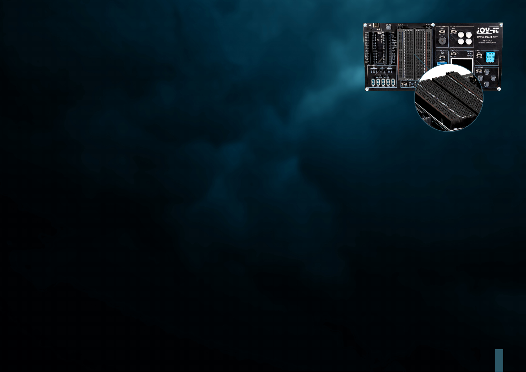
. BREADBOARD
Breadboards are an indispensable tool in the world of electronics, much like interface connectors are
crucial for connecting dierent components. They allow electronic circuits to be built and tested quickly
and without soldering, making them particularly popular for prototyping and educational purposes.
A breadboard typically consists of a rectangular plastic block with a large number of embedded holes
arranged in rows. These holes are internally connected by metallic traces that allow components and wires
to be easily plugged in and connected. The standard layout of a breadboard includes two main areas:
The main areas: These consist of a series of parallel rows of holes, usually separated by a central groove. The holes within a row are electrically connected
to each other. This arrangement is ideal for inserting integrated circuits (ICs) and other components.
The power strips: At the edge of the breadboard there are usually one or two rows of holes that serve as power strips. These are connected vertically along
the entire length of the breadboard and oer a convenient way of providing power and ground at various points on the circuit.
The flexibility of a breadboard lies in its reusability and the ability to build circuits without permanent changes. This makes it ideal for experimentation as
errors can be easily corrected and components removed without damage. It is also an excellent learning tool as it promotes understanding of circuit logic
and component functions in a practical, visual way.
In addition, breadboards are available in dierent sizes and with dierent numbers of connection points to suit dierent requirements. Smaller breadboards
are good for simple projects and experiments, while larger ones are suitable for more complex circuits.
Despite their versatility, breadboards also have limitations. They are not well suited for very high frequencies or for circuits that require high power. Also, the
connections can sometimes be less reliable than soldered connections, especially if the breadboard wears out over time.
Overall, breadboards are an essential tool for anyone working with electronics - from beginners learning the basics to experienced developers looking to
prototype quickly and eiciently. They are the electronic equivalent of an artist's sketchbook: a place to explore ideas and experiment before the final work
is created.
16
Page 17

. INFORMATION & TAKE-BACK OBLIGATIONS
OUR INFORMATION AND TAKE-BACK OBLIGATIONS UNDER THE GERMAN ELECTRICAL AND ELECTRONIC EQUIPMENT ACT (ELEKTROG)
SYMBOL ON ELECTRICAL AND ELECTRONIC EQUIPMENT:
This crossed-out garbage can means that electrical and electronic appliances do not belong in household waste. You must hand in the old appliances at a
collection point. Before handing them in, you must separate used batteries and accumulators that are not enclosed by the old appliance.
RETURN OPTIONS:
As an end user, you can hand in your old appliance (which essentially fulfills the same function as the new appliance purchased from us) for disposal free
of charge when purchasing a new appliance. Small appliances with no external dimensions greater than 25 cm can be disposed of in normal household
quantities regardless of whether you have purchased a new appliance.
POSSIBILITY OF RETURN AT OUR COMPANY LOCATION DURING OPENING HOURS:
SIMAC Electronics GmbH, Pascalstr. 8, D-47506 Neukirchen-Vluyn
RETURN OPTION IN YOUR AREA:
We will send you a parcel stamp with which you can return the device to us free of charge. To do so, please contact us by e-mail at [email protected] or by
telephone.
PACKAGING INFORMATION:
Please pack your old appliance securely for transportation. If you do not have suitable packaging material or do not wish to use your own, please contact us
and we will send you suitable packaging.
17
Page 18

. SUPPORT
We are also there for you aer your purchase. If any questions remain unanswered or problems arise, we are also available to assist you by e-mail, telephone
and ticket support system.
E-Mail: [email protected]
Ticket-System: http://support.joy-it.net
Telephone: +49 (0)2845 9360 – 50 (Mon. - Thur.: 09:00 - 17:00 ó clock, Fri.: 09:00 - 14:30 ó clock)
For further information, please visit our website:
WWW.JOY-IT.NET
18
 Loading...