

Page 1
3
3
Mega2560 R3 Starter Kit
Ausgabe 19.05.2017 Copyright by Joy-IT 1
Page 2

3
Index
1 General informaons & technical data
2 Assignment
3 Soware installaon
3.1 Soware setup
4 EU-Declaraon of conformity
5 Project-examples
5.1 Project 1: Hello World
5.2 Project 2: ashing LED
5.3 Project 3: PWM Lightcontrol
5.4 Project 4: Trac lights
5.5 Project 5: LED chasing eect
5.6 Project 6: Buon controlled LED
5.7 Project 7: Responder experiment
5.8 Project 8: Acve buzzer
5.9 Project 9: Passive buzzer
5.10 Project 10: Reading analog values
5.11 Project 11: Light dependent resistor
5.12 Project 12: Flamesensor
5.13 Project 13: Tilt switch
5.14 Project 14: 1-Digit LED segment display
5.15 Project 15: 4-Digit LED segment display
5.16 Project 16: LM35 Temperature-sensor
5.17 Project 17: 74HC595
5.18 Project 18: RGB LED
5.19 Project 19: Infrarot remote control
5.20 Project 20: 8x8 LED Matrix
Mega2560 R3 Star-
Ausgabe 19.05.2017 Copyright by Joy-IT 2
Page 3

Dear customer,
thank you for purchasing our product.
Please nd our instrucons below.
1. General informaons & technical data
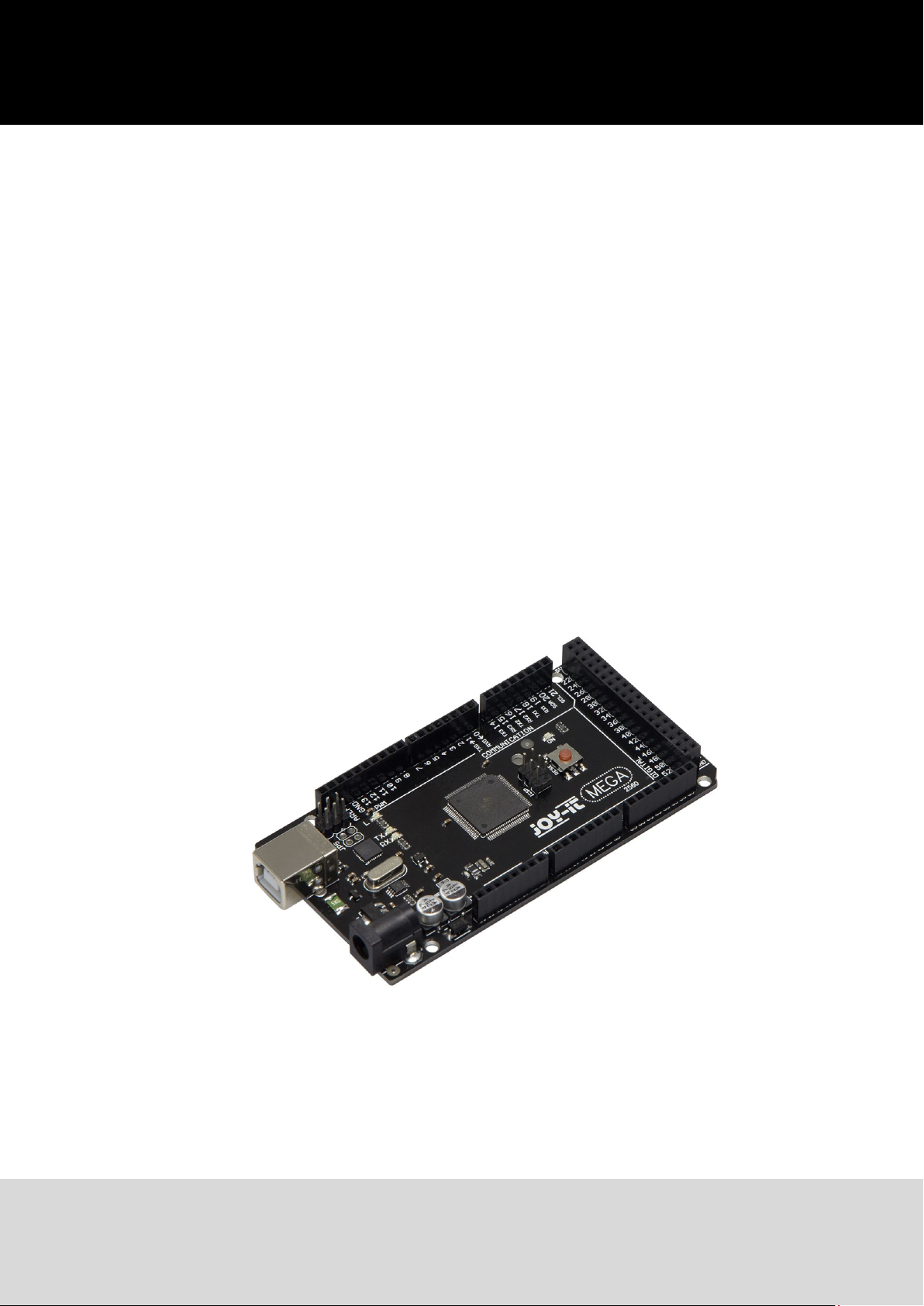
Our board is a high quality reproducon and fully compable with the Arduino Mega 2560.
We would, however, like to emphasize that this is not an original Arduino.
The Mega board is the right microcontrollerboard for everyone who wants to quickly join the
programmers world.
This set will lead you to a variety of projects.
Its ATMega2560-Microcontroller oers you enough performance for your ideas and projects. It has a size
of 101.52 mm x 53.3 mm and includes 54 digital in– and outputs and 16 analog inputs.
Model ARD_Mega2560R3
Microcontroller ATmega2560
Input voltage 7-12V
Input current (max.) 6-20V
Digital IO 54 (14 mit PWM)
Analog IO 16
DC current IO 40mA
DC current 3.3V 50mA
Memory 256kB (8kB für Bootloader)
SRAM 8kB
EEPROM 4kB
Clock Speed 16 MHz
Dimensions 101.52mm x 53.3mm
Ausgabe 19.05.2017 Copyright by Joy-IT 3
Page 4
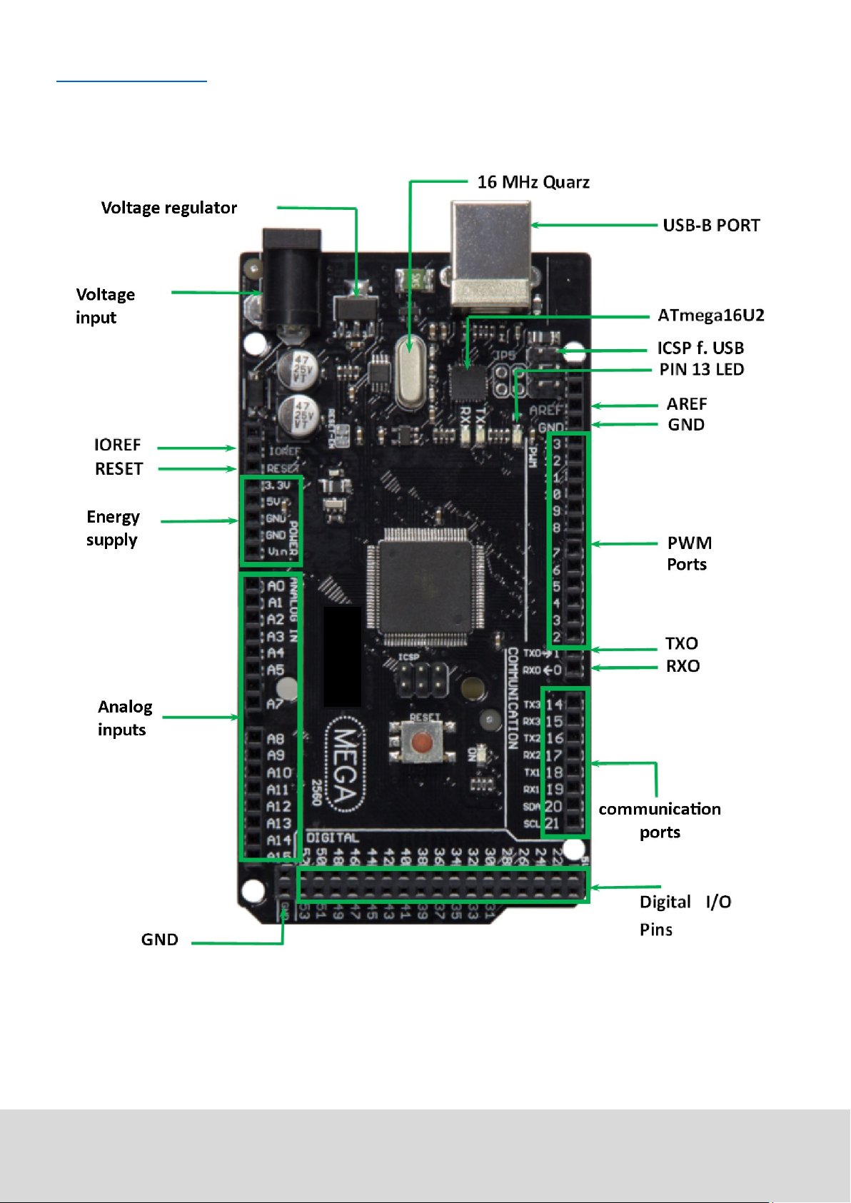
2. Assignment
Ausgabe 19.05.2017 Copyright by Joy-IT 4
Page 5
3. Soware installaon
To start programming your JOY-IT ARD_Mega2560R3, you need to install the development environment,
and, of course, the drivers, on your computer.
The Arduino IDE is best for using with the Mega2560.
It is licensed as open source soware under the GPLv2 terms and ist concept and design is aiming for
beginners.
This IDE is completely compable to our Mega2560R3 board and oers you every driver you need for a
quick start.
You can download the soware here.
3.1 Soware setup
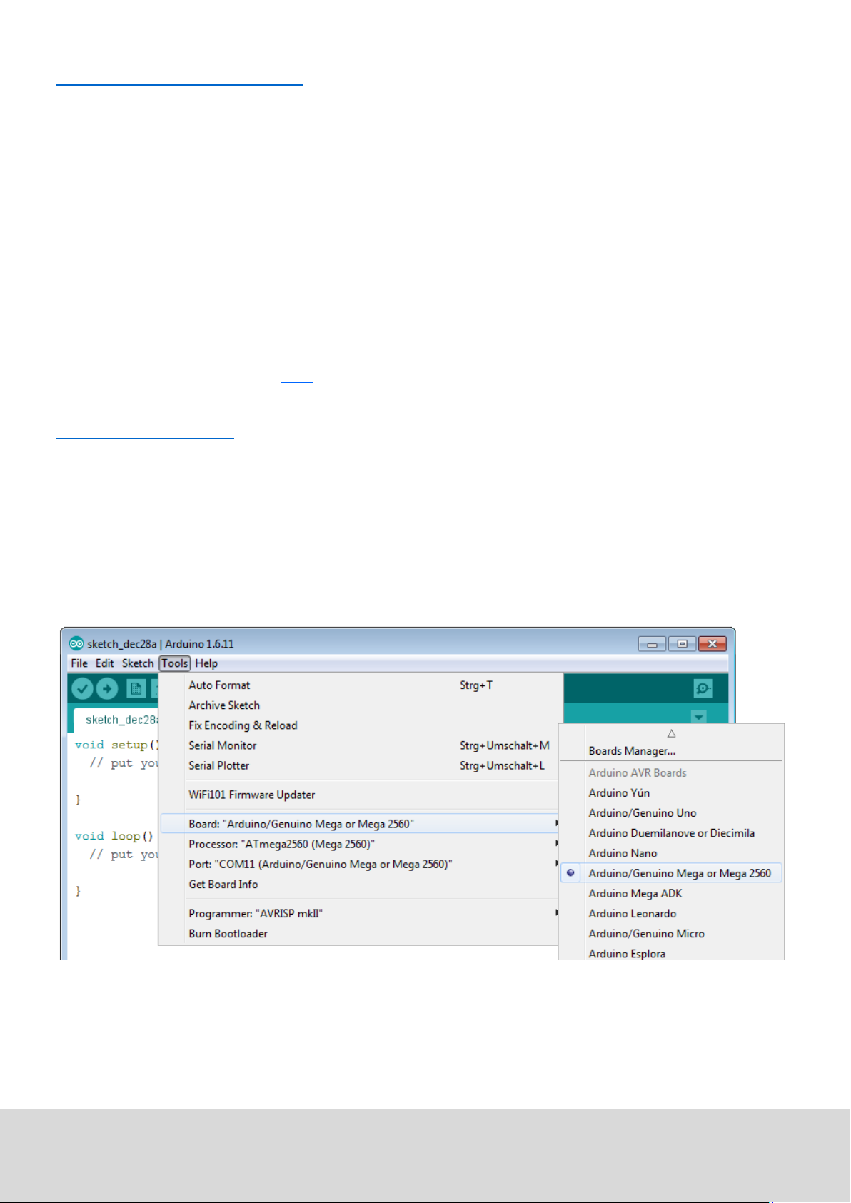
Aer installing the soware, you need to choose the right microcontroller-board in the environment.
Therefore you need to be aware of two steps:
1. Choose „Arduino/Genuino Mega or Mega 2560“ at [Tools->Board].
Ausgabe 19.05.2017 Copyright by Joy-IT 5
Page 6
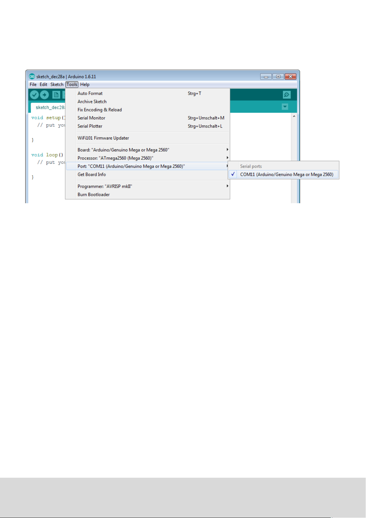
2. Choose the right port (marked with Arduino/Genuino Mega or Mega 2560) at [Tools -> Port].
Ausgabe 19.05.2017 Copyright by Joy-IT 6
Page 7

4 EU-Declaraon of conformity
Manufacturer JOY-iT Europe GmbH
Pascalstr. 8
47506 Neukirchen-Vluyn
Arcle descripon: ard_mega2560R3 /ARD-Set01
Descripon: Microcontroller-Board / Set
Purpose: experimental setup / prototyping
The manufacturer, the JOY-IT Europe GmbH, Pascalstr. 8, D-47506 Neukirchen-Vluyn, declares that the
product „ard_Mega2560IP“ is, during operaon according to regulaons, in compliance with the
fundamental requirements of the following guidelines:
2014/ 30/EU (EMV) & 2011/65/EU (Rohs)
The following standards has been applied for assessment:
EN 61326-1: 2013
electrical equipment for measure-, control– and laboratorydevices - EMV requirement part 1 general requirements
Date Name Signature Posion
03.03.2017 Yue Yang Director
Ausgabe 19.05.2017 Copyright by Joy-IT 7
Page 8
5 Project examples
5.1 Project 1: „Hello World“
We start with an easy one.
You just need the board and an USB cable to start with the „Hello World!“ project.
This is an communicaon test for your Mega2560 and your computer and a basic project for your rst
steps in the Arduino world.
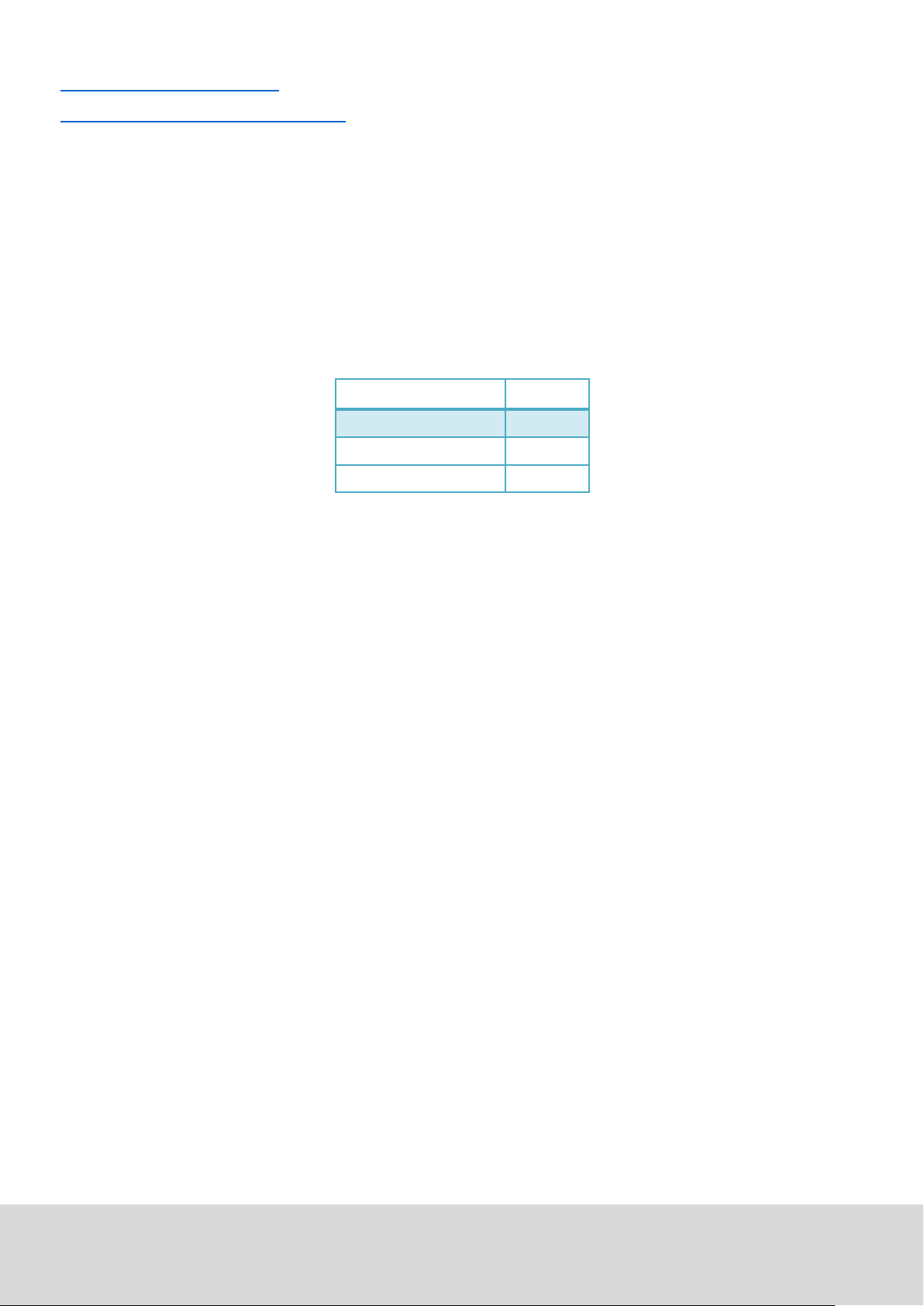
Aer compleng the drivers installaon, let‘s open the Arduino soware and write some code, which
displays „Hello World“ underneath your code.
Of course you can create some code, which is going to repeat the message automacally.
We can instruct the LED on PIN 13 to blink at rst and to output „Hello World“ aerwars.
Hardware Amount
Mega2560 board 1
USB cable 1
LED 1
Ausgabe 19.05.2017 Copyright by Joy-IT 8
Page 9

int val; // defines variable “Val”
int ledpin=13; // defines digital interface 13
void setup()
{
Serial.begin(9600); // sets baudrate to 9600 to comply
// with software configurationre
pinMode(ledpin,OUTPUT); // sets digital PIN 13 to output.
// This configuration is requi
//red when using I/O ports.}
void loop()
{
val=Serial.read(); // reads symbols and assigns to „Val“
if(val=='R') // checks input for the letter „R“
{ // if so, turn on LED at PIN 13
digitalWrite(ledpin,HIGH);
delay(500);
digitalWrite(ledpin,LOW); // turns off LED
delay(500);
Serial.println("Hello World!"); // shows “Hello World”
}
}
Ausgabe 19.05.2017 Copyright by Joy-IT 9
Page 10
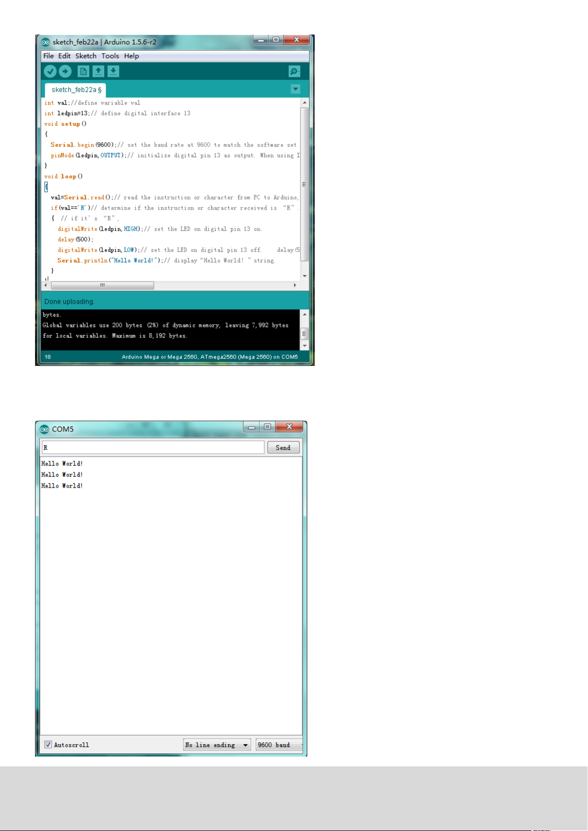
Open the serial monitor and insert a „R“.
The LED is going to light up once and you will see „Hello World“ in the serial monitor.
Ausgabe 19.05.2017 Copyright by Joy-IT 10
Page 11
5.2 Project 2: ashing LED
The ashing LED project is quite easy.
We already discovered the LED in the previous project.
This me we will connect the LED to a digital port.
Diesmal werden wir eine LED mit einem der digitalen Pins verbinden.
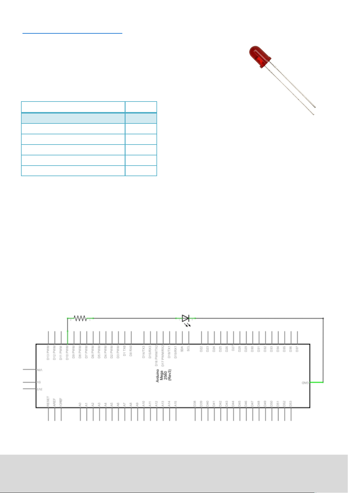
This is what we need:
Hardware Amount
Mega2560 board 1
USB cable 1
Red M5 LED 1
220Ω resistor 1
Breadboard 1
Breadboard cable 2
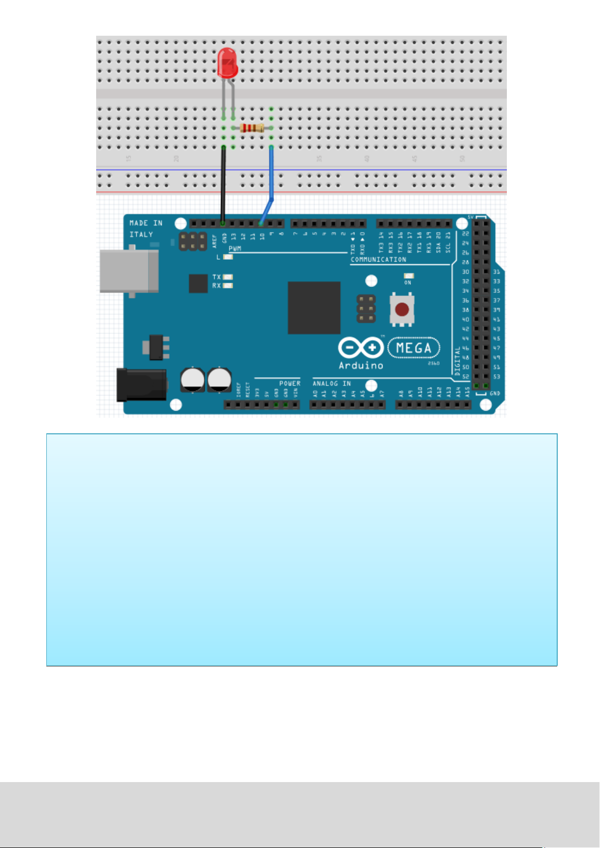
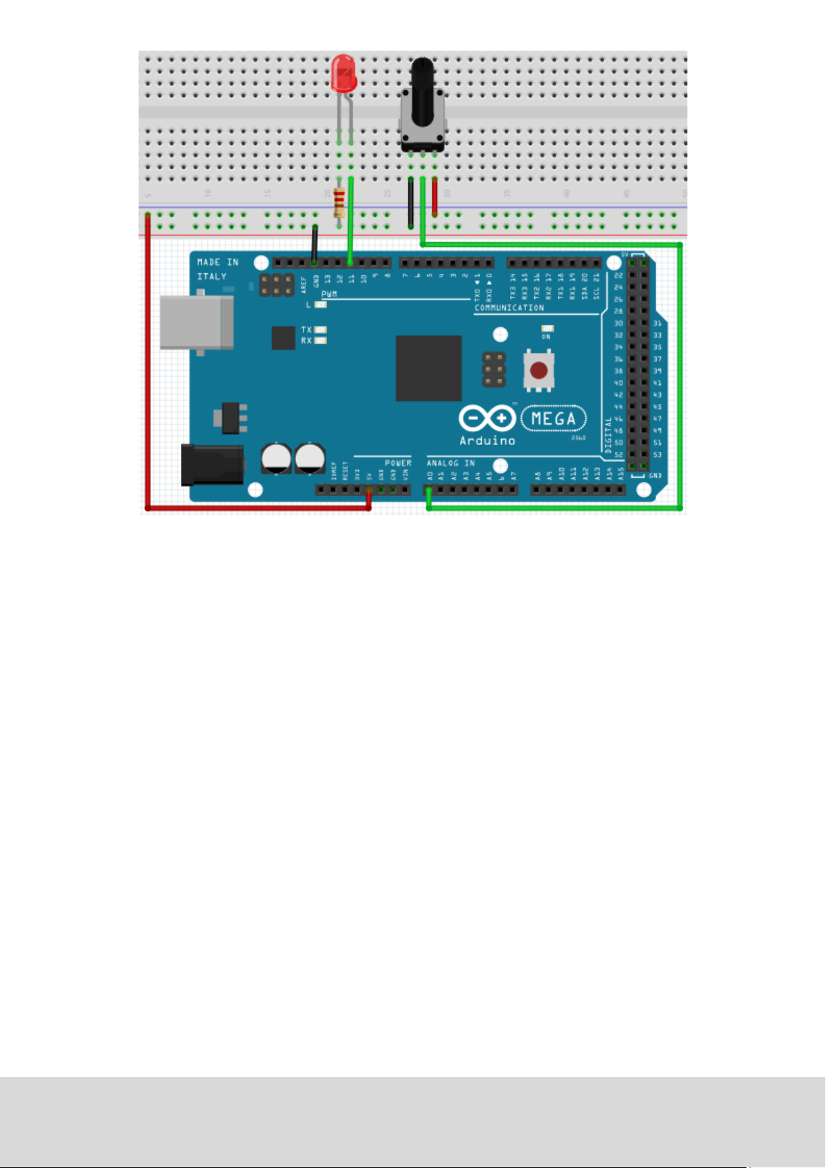
Just connect the components as seen in the circuit diagram below.
We are going to use digital pin 10.
Connect the LED to a 220 Ohm resistor to avoid damage by higher currents.
Ausgabe 19.05.2017 Copyright by Joy-IT 11
Page 12
int ledPin = 10; // Defines digital PIN 10.
void setup()
{
pinMode(ledPin, OUTPUT); // Defines PIN with connected LED as
// output
}
void loop()
{
digitalWrite(ledPin, HIGH); // turns on LED
delay(1000); // waits a second
digitalWrite(ledPin, LOW); // turns off LED
delay(1000); // waits a second
}
Nach dem Runterladen dieses Programms, wirst du im Experiment die an Pin 10 verbundene LED sich, mit
einem Intervall von ca. einer Sekunde, Ein- und Ausschalten sehen.
Ausgabe 19.05.2017 Copyright by Joy-IT 12
Page 13
5.3 Project 3: PWM Lightcontrol
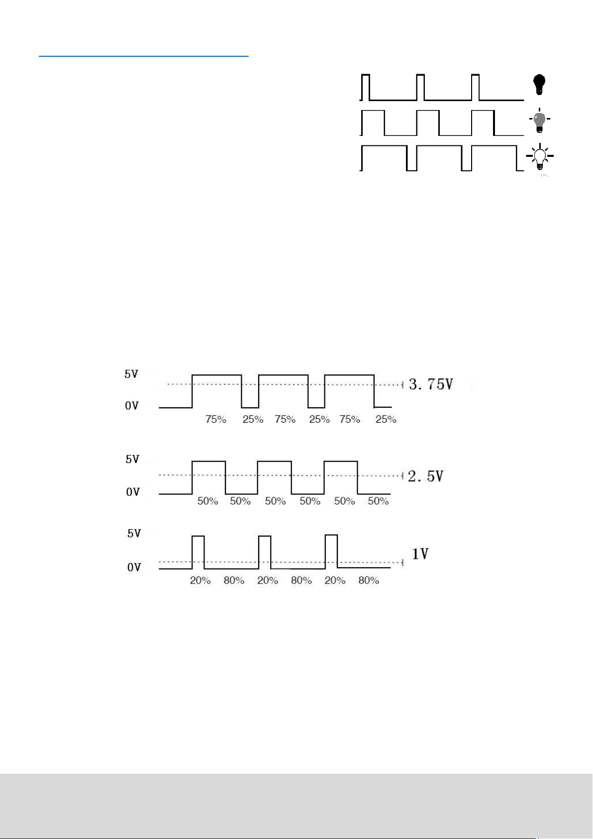
PWM, short for Pulse Width Modulaon, is a technique, used to
translate analog signals into digital signals.
A computer is not able to output an analog voltage.
Er kann nur Digitalspannung ausgeben mit Werten wie 0V oder
5V.
Therefore, a high-resoluon counter is used, to code an analog
signal level, by modulang the occupancy rate of PWM.
The voltage and current is led by repeated pulse sequences to the component.
Every analog value can be decoded by PWM, if the bandwith is appropiated.
The value of the outputvoltage is calculated with the duraon of the on and o condions.
Voltage = (ON duraon / pulse duraon) * maximum voltage
PWM has many uses: control of lighntensity, control of motor speed etc.
Ausgabe 19.05.2017 Copyright by Joy-IT 13
Page 14
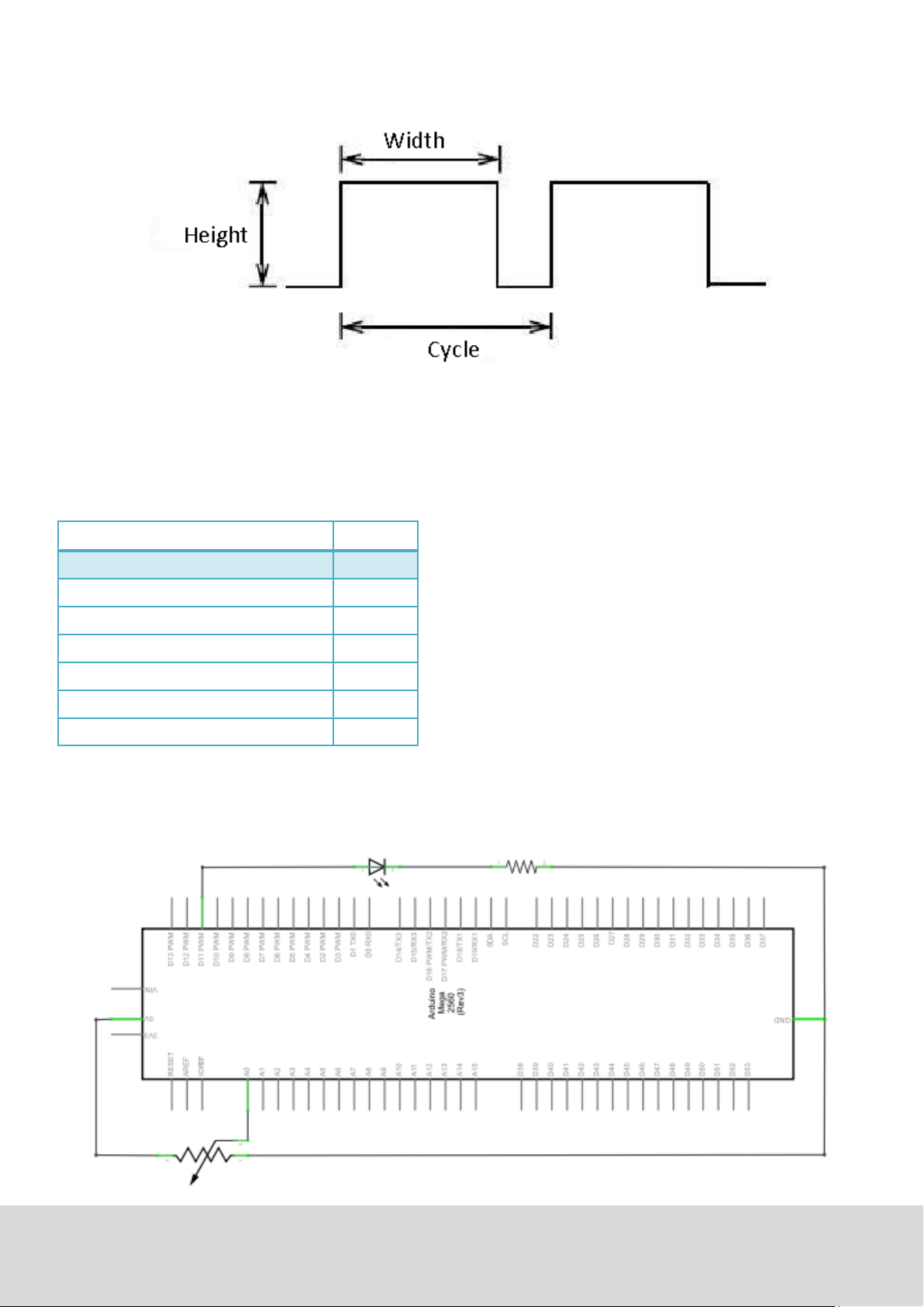
The three basic parameters of PWM:
1. Die amplitude of the pulse width (minimum/maximum)
2. Pulsefrequency
3. Voltage level
The Mega2560 has 6 interfaces, supporng PWM: digital PIN 3, 5, 6, 9, 10 and 11.
Hardware Amount
In a previous project, we used a digital signal to control a
LED.
Mega2560 Plane 1
USB Kabel 1
Rote M5 LED 1
Variabler Widerstand 1
Now we are going to use a potenometer to adjust the
brightness of the LED.
220Ω Widerstand 1
Breadboard 1
Breadboard Überbrückungskabel 6
Ausgabe 19.05.2017 Copyright by Joy-IT 14
Page 15
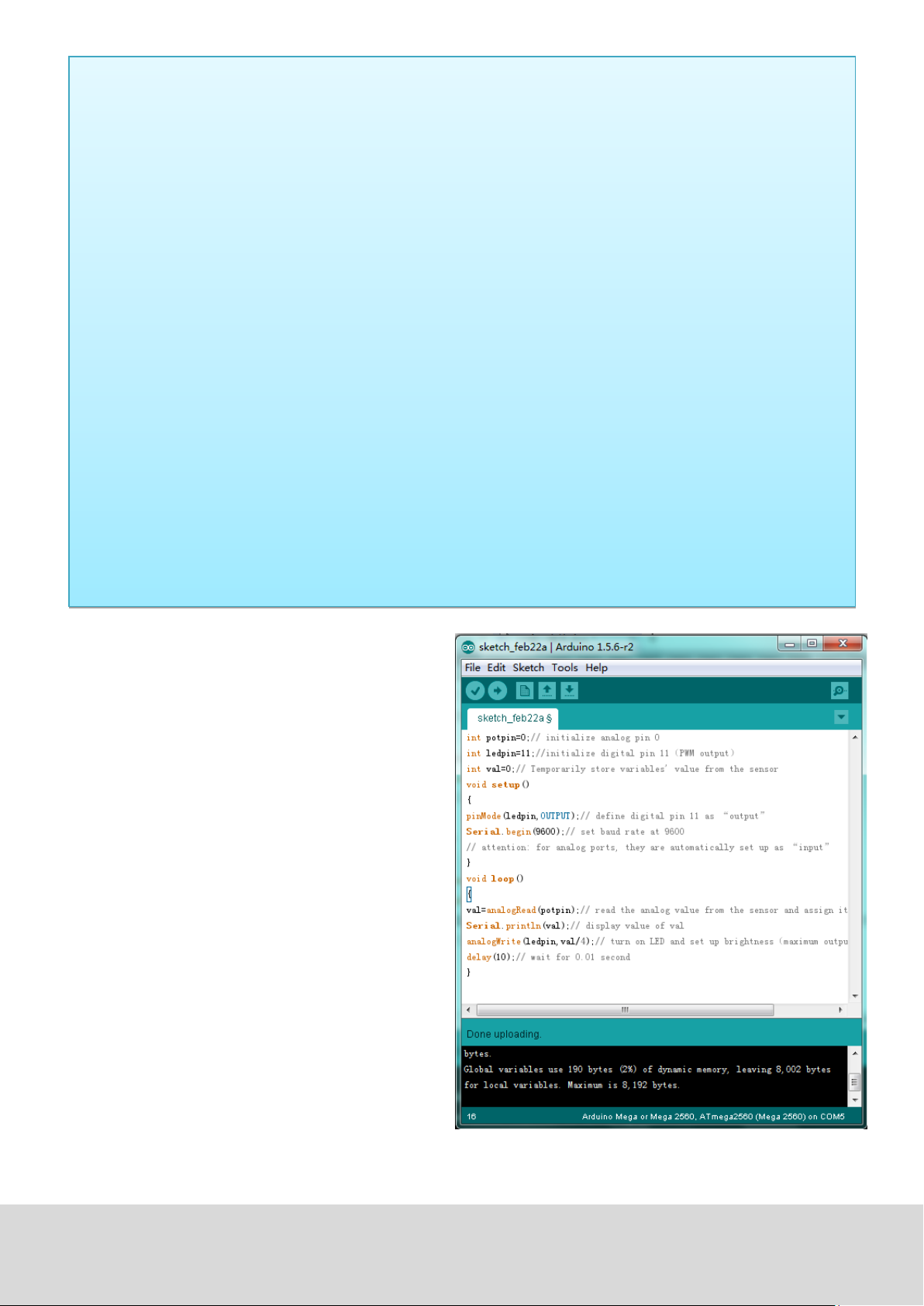
While creang this program, we will make use of the analog wring funcon.
In this experiment, we are going to read the analog value of the potenmeter and assign this value to the
PWM port, to noce a change of LED brightness.
The last part will be to show the analog value on the screen.
Ausgabe 19.05.2017 Copyright by Joy-IT 15
Page 16
int potpin=0; // inialises analog PIN 0
int ledpin=11; // inialises digital PIN 11 (PWM output)
int val=0; // saves the value of the sensor
void setup()
{
pinMode(ledpin,OUTPUT); // sets digital PIN 11 to output
Serial.begin(9600); // sets baudrate to 9600
}
void loop()
{
val=analogRead(potpin); // reads analog value and assigns it to „Val“
Serial.println(val); // shows „Val“ value
analogWrite(ledpin,val/4); // turns on LED and assigns brightness
//(maximum PWM output is 255)
delay(10); // waits 0,01 seconds
}
Aer transferring the code, we can noce the
value changing by moving the potenometer.
We can also noce the brightness of the LED
changing.
Ausgabe 19.05.2017 Copyright by Joy-IT 16
Page 17
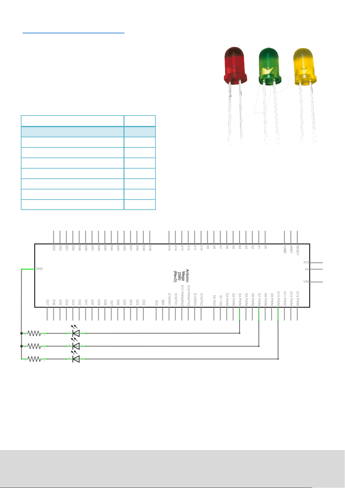
5.4. Projekt 4: Trac lights
We already discovered the ashing LED project.
Now it is me to do a more complicated experiment:
Trac lights
During this experiment we will used three LEDs with dierecnt
colors.
Hardware Amount
Mega2560 board 1
USB cable 1
Red M5 LED 1
Yellow M5 LED 1
Green M5 LED 1
220Ω resistor 3
Breadboard 1
Breadboard cable 4
Ausgabe 19.05.2017 Copyright by Joy-IT 17
Page 18
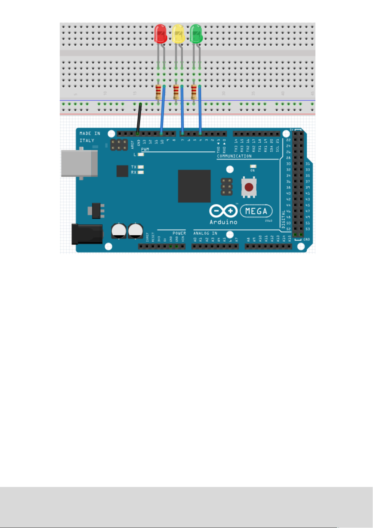
Because this is a simulaon of trac lights, the lighng duraon should be as long as real trac lights.
Therefore we are going to use the Arduinos delayfuncon, to control the delay.
Ausgabe 19.05.2017 Copyright by Joy-IT 18
Page 19

int redled =10; // initialises digital PIN 8
int yellowled =7; // initialises digital PIN 7
int greenled =4; // initialises digital PIN 4
void setup()
{
pinMode(redled, OUTPUT); // sets red LED PIN to output
pinMode(yellowled, OUTPUT); // sets yellow LED PIN to output
pinMode(greenled, OUTPUT); // sets green LED PIN to output
}
void loop()
{
digitalWrite(greenled, HIGH); // turns on green LED
delay(5000); // waits 5 seconds
digitalWrite(greenled, LOW); // turns off green LED
for(int i=0;i<3;i++) // flashes 3x
{
delay(5000); // waits 5 seconds
digitalWrite(yellowled, HIGH); // turns on yellow LED
delay(5000); // waits 5 seconds
digitalWrite(yellowled, LOW); // turns off yellow LED
}
delay(5000); // waits 5 seconds
digitalWrite(redled, HIGH); // turns on red LED
delay(5000); // waits 5 seconds
digitalWrite(redled, LOW); // turns off red LED
}
You can watch the trac lights, aer the transfer is complete.
The green light is going to light up for ve seconds.
The yellow light then ashes three mes.
The green light will then light up for another ve seconds.
Then the yellow light wll ash three mes again.
In the end the red light will light up for three seconds and completes the cycle.
Ausgabe 19.05.2017 Copyright by Joy-IT 19
Page 20

5.5 Project 5: LED Chase-Eect
We oen see billboards with colorful LEDs.
These are always changing to form dierent eects.
This experiment will simulate this eect.
Hardware Amount
Mega2560 board 1
USB cable 1
LED 6
220Ω resistor 6
Breadboard 1
Breadboard cable 12
Ausgabe 19.05.2017 Copyright by Joy-IT 20
Page 21

int BASE = 2 ; // I/O PIN for the first LED
int NUM = 6; // Amount of LEDs
void setup()
{
for (int i = BASE; i < (BASE + NUM); i ++)
{
pinMode(i, OUTPUT); // sets I/O PINs to output
}
}
void loop()
{
for (int i = BASE; i < (BASE + NUM); i ++)
{
digitalWrite(i, LOW); // sets I/O PIN to „low“, turns on LEDs
// one after the other die LEDs
delay(200); // delay
}
for (int i = BASE; i < (BASE + NUM); i ++)
{
digitalWrite(i, HIGH); // sets I/O PIN to „high“,
// turns off LEDs one after the other
delay(200); // delay
}
}
Ausgabe 19.05.2017 Copyright by Joy-IT 21
Page 22

5.6 Project 6: buon-controled LED
I/O Port is the interface for input and output.
Unl now we have just used the output.
In this project we will try to use the input to read the value of
the connected component.
We will use a buon and a LED with the input and output to
give a beer unterstanding of the I/O funcon.
Buons have a digital value.
If the buon is pressed, the circuit is closed and gets in a
conducve state.
Hardware Amount
Mega2560 board 1
USB cable 1
LED 1
220Ω resistor 1
10kΩ resisotr 1
Buon 1
Breadboard 1
Breadboard cable 5
Ausgabe 19.05.2017 Copyright by Joy-IT 22
Page 23

By pressing the buon, the LED will light up.
In this program, an if query is used.
int ledpin=11; // initalises PIN 11
int inpin=7; // initialises PIN 7
int val; // defines „Val”
void setup()
{
pinMode(ledpin,OUTPUT); // sets LED PIN to „OUTPUT“
pinMode(inpin,INPUT); // sets button PIN to „INPUT“
}
void loop()
{
val=digitalRead(inpin); // reads value of PIN 7
// assigns to „Val“
if(val==LOW) // checks if button is pressed
// if so, LED lights up
{ digitalWrite(ledpin,LOW);}
else
{ digitalWrite(ledpin,HIGH);}
}
If the buon is pressed, the LED will light up.
Otherwise it will stay o.
Ausgabe 19.05.2017 Copyright by Joy-IT 23
Page 24

5.7 Project 7: Responder experiment
In this program are three buons and one reset buon which will control the three LEDs with 7 digital I/O
PINs.
Hardware Amount
Mega2560 board 1
USB cable 1
Red M5 LED 1
Yellow M5 LED 1
Green M5 LED 1
220Ω resistor 7
Buons 4
Breadboard 1
Breadboard cable 13
Ausgabe 19.05.2017 Copyright by Joy-IT 24
Page 25

int redled=8; // sets red LED to „Output“
int yellowled=7; // sets yellow LED to „Output“
int greenled=6; // sets green LED to „Output“
int redpin=5; // initialises PIN for red button
int yellowpin=4; // initialises PIN for yellow button
int greenpin=3; // initialises PIN for green button
int restpin=2; // initialises PIN for reset button
int red;
int yellow;
int green;
void setup()
{
pinMode(redled,OUTPUT);
pinMode(yellowled,OUTPUT);
pinMode(greenled,OUTPUT);
pinMode(redpin,INPUT);
pinMode(yellowpin,INPUT);
pinMode(greenpin,INPUT);
}
void loop() //reads the buttons repetitive
{
red=digitalRead(redpin);
yellow=digitalRead(yellowpin);
green=digitalRead(greenpin);
if(red==LOW)RED_YES();
if(yellow==LOW)YELLOW_YES();
if(green==LOW)GREEN_YES();
}
void RED_YES() // executes the code until the red LED is
// on. Ends the circle when the reset
// button is pressed.
{
while(digitalRead(restpin)==1)
{
digitalWrite(redled,HIGH);
digitalWrite(greenled,LOW);
digitalWrite(yellowled,LOW);
}
clear_led();
}
Ausgabe 19.05.2017 Copyright by Joy-IT 25
Page 26

void YELLOW_YES() // executes the code until the yellow LED
// is on. Ends the circle when the reset
// button is pressed.
{
while(digitalRead(restpin)==1)
{
digitalWrite(redled,LOW);
digitalWrite(greenled,LOW);
digitalWrite(yellowled,HIGH);
}
clear_led();
}
void GREEN_YES() // executes the code until the green LED
// is on. Ends the circle when the reset
// button is pressed.
{
while(digitalRead(restpin)==1)
{
digitalWrite(redled,LOW);
digitalWrite(greenled,HIGH);
digitalWrite(yellowled,LOW);
}
clear_led();
}
void clear_led() // turns all LEDs off
{
digitalWrite(redled,LOW);
digitalWrite(greenled,LOW);
digitalWrite(yellowled,LOW);
}
Achten Sie bie darauf, dass Sie beide Code-Teile in ihrem Sketch des Arduino-Programms
zusammenfügen.
Wenn eine Taste betägt wird, schaltet sich die entsprechende LED ein.
Wird die Reset-Taste betägt, schaltet sich die entsprechende LED wieder aus.
Ausgabe 19.05.2017 Copyright by Joy-IT 26
Page 27

5.8 Project 8: Acve buzzer
Acve buzzers are used in computers, printers, alarm clocks, toys etc. to
emit a sound.
It has an inner vibraon source.
Connected to a 5V-Power-supply, it can buzz repeatedly.
Hardware Amount
Mega2560 board 1
USB cable 1
Buzzer 1
Breadboard 1
Breadboard cable 2
Ausgabe 19.05.2017 Copyright by Joy-IT 27
Page 28

int buzzer=8; // initialises digital I/O PIN
// to control the buzzer
void setup()
{
pinMode(buzzer,OUTPUT); // sets pinmode to Output
}
void loop()
{
digitalWrite(buzzer, HIGH); // makes sounds
}
Das Projekt ist nach dem Übertragen des Programms abgeschlossen.
Der Summer summt.
Ausgabe 19.05.2017 Copyright by Joy-IT 28
Page 29

5.9 Project 9: Passive buzzer
With the Mega2560, many interacve projects are possible.
The previous projects mainly dealt with LEDs but an oen
used project is the acousc-opc display.
Therefore, a passive buzzer is used which is, unlike the
acve buzzer, not able to acvate itself.
The acvaon occurs over a pulse frequency.
Dierent frequencs result in dierent sounds.
You can use this to play the melody of a song.
Hardware Amount
Mega2560 board 1
USB cable 1
Passive buzzer 1
Breadboard 1
Breadboard cable 2
Ausgabe 19.05.2017 Copyright by Joy-IT 29
Page 30

int buzzer=8;
void setup()
{
pinMode(buzzer,OUTPUT); // sets buzzer Pin to output.
}
void loop()
{
unsigned char i,j; // defines variable
while(1)
{
for(i=0;i<80;i++) // emits frequencysound
{
digitalWrite(buzzer,HIGH); // Sound
delay(1); // 1ms delay
digitalWrite(buzzer,LOW); // No sound
delay(1); // 1ms delay
}
for(i=0;i<100;i++) // emits frequencysound
{
digitalWrite(buzzer,HIGH); // Sound
digitalWrite(buzzer,LOW); // No Sound
delay(2); // 2ms delay
}
}
}
Ausgabe 19.05.2017 Copyright by Joy-IT 30
Page 31

5.10 Project 10: Reading analog values
This project is about the analog interfaces of the Mega2560.
An analogRead() command can the value of the interface.
Because of the Analog-Digital-Converter of the Mega2560, the read-out values are between 0 and 1023.
To be able to read the values, it is important to take care of the right baudrate.
The baudrate of the computer has to meet the requirements of the device.
If you open the serial monitor in your Arduino program, you can congure the baudrate in the boom
right corner.
Here we are going to convert the adjustes value of a potenometer to an analog value and display it on
the screen.
Hardware Amount
Mega2560 board 1
USB cable 1
Potenometer 1
Breadboard 1
Breadboard cable 3
Ausgabe 19.05.2017 Copyright by Joy-IT 31
Page 32

int potpin=0; // initialises analog PIN 0
int ledpin=13; // initialises digital PIN 13
int val=0; // defines „Val“
void setup()
{
pinMode(ledpin,OUTPUT); // sets digital PIN to „Output“
Serial.begin(9600); // sets Baudrate to 9600
}
void loop()
{
digitalWrite(ledpin,HIGH); // turns on LED
delay(50); // waits 0,05 seconds
digitalWrite(ledpin,LOW); // turns off
delay(50); // waits 0,05 seconds
val=analogRead(potpin); // reads Analogvalue
Serial.println(val); // Shows Analogvalue(saved in „Val“)
}
The read out values are displayed in the serial montor.
Ausgabe 19.05.2017 Copyright by Joy-IT 32
Page 33

5.11 Project 11: Light dependent resistor
A light dependent resistor is a resistor which is changing its value by the
incoming light.
It is based on the photoelectric eect of semiconductors.
If the incoming light is intensive, it reduces its power of resistance.
If the incoming light is low, it raises its power of resistance.
Light dependent resistors are usually used for light measurement, light
control and for photovoltaic-conversion.
We will use this eect to control the light intensity of a LED.
Hardware Amount
Mega2560 board 1
USB cable 1
Red M5 LED 1
Light dependent resistor 1
220Ω resistor 1
10kΩ resistor 1
Breadboard 1
Breadboard cable 5
Ausgabe 19.05.2017 Copyright by Joy-IT 33
Page 34

int potpin=0; // initialises analog PIN 0 an
int ledpin=11; // initialises digital PIN 11. Ausgang
int val=0; // initialises variable „Val“
void setup()
{
pinMode(ledpin,OUTPUT); // sets Pin 11 to output
Serial.begin(9600); // sets baudrate to „9600“
}
void loop()
{
val=analogRead(potpin); // reads analog value of the sensor
Serial.println(val); // shows analog value in „Val“
analogWrite(ledpin,val); // turns on LED and sets brightness
delay(10); // waits 0,01 seconds
}
Ausgabe 19.05.2017 Copyright by Joy-IT 34
Page 35

5.12 Project 12: Flamesensor
The Flamesensor (infrared receiving triode) is specially used by robots
to nd amesources.
This sensor has a high sensivity to ames because infrared rays are
very sensive to re.
It has a specially build Infared-Receiverpipe to detect re and convert
the light of the ames to a signal.
These signals are processed by the central processor.
If the sensor is approaching a re, the analog voltage is changing.
If no re is close, the voltage is by roughly 0.3V.
If a re is close, the voltage is at 1V.
The higher the voltage, the closer the re.
Hardware Amount
Mega2560 board 1
USB cable 1
Flamesensor 1
Buzzer 1
10kΩ Resistor 1
Breadboard 1
Breadboard cable 6
Ausgabe 19.05.2017 Copyright by Joy-IT 35
Page 36

int flame=0; // selects analog PIN 0 for sensor
int Beep=9; // selects digital PIN9 for buzzer
int val=0; // initialises variable
void setup()
{
pinMode(Beep,OUTPUT); // sets buzzer PIN to „output“
pinMode(flame,INPUT); // sets flame semsor PIN to „input“
Serial.begin(9600); // sets baudrate to „9600“
}
void loop()
{
val=analogRead(flame); // reads the sensors analog value
Serial.println(val); // prints the value
if(val>=600) // buzzer beeps if value over 600
{
digitalWrite(Beep,HIGH);
}else
{
digitalWrite(Beep,LOW);
}
delay(500);
}
Ausgabe 19.05.2017 Copyright by Joy-IT 36
Page 37

5.13 Project 13: Tilt switch
We are going to use the lt switch to control the on and o switch of a LED.
The switch is on if the lt switch is below a horizontal posion.
We can use the voltagevalue of the analog port, on which the lt switch is
connected to, to measure the posion of the switch.
Hardware Amount
Mega2560 board 1
USB cable 1
Tilt switch 1
Red M5 LED 1
220Ω Resistor 1
Breadboard 1
Breadboard cable 5
Ausgabe 19.05.2017 Copyright by Joy-IT 37
Page 38

void setup()
{
pinMode(8,OUTPUT); // sets digital PIN 8 to „output“
}
void loop()
{
int i; // denes variable i
while(1)
{
i=analogRead(5); // reads the voltage value on analog PIN 5
if(i>512) // if higher then 512 (= 2.5V)
{
digitalWrite(8,LOW); // turn on LED
}
else // otherwise
{
digitalWrite(8,HIGH); // turn o LED
}
}
}
Wird das Breadboard bis zu einem besmmten Grad geneigt, so schaltet sich die LED ein.
Falls es keine Neigung gibt, bleibt die LED aus.
Ausgabe 19.05.2017 Copyright by Joy-IT 38
Page 39

5.14 Project 14: 1-digit LED segment display
The LED segment displays are very common displays for numeric informaons.
They are oen used in electric ovens, washing machines, water-temperature
displays and electric clocks.
The LED segment display is a semi-conductor and a light eming devie.
Its base-unit is a LED:
The segment display can be devided in a 7-segement and a 8-segment display.
The 8-segment display contains one more LED-unit (for the decimal dot).
Depending on the wiring, the displays can also be devided in displays with common anode and common
cathode.
The display with common anode combines every anodes to one common anode (COM).
If you are using a display with a common anode, the common anode (COM) has to be connected to +5V.
If the cathode-level of a segment is low, the segment is acvated.
If you are using a display with a common cathode, the common cathode (COM) has to be connected to
GND.
Ausgabe 19.05.2017 Copyright by Joy-IT 39
Page 40

Hardware Amount
Mega2560 board 1
USB cable 1
8-Segment display 1
220Ω Resistor 8
Breadboard 1
Breadboard cabel 12
Ausgabe 19.05.2017 Copyright by Joy-IT 40
Page 41

// sets the IO PIN for every segment
int a=7; // digital PIN 7 for segment a
int b=6; // digital PIN 6 for segment b
int c=5; // digital PIN 5 for segment c
int d=10; // digital PIN 10 for segment d
int e=11; // digital PIN 11 for segment e
int f=8; // digital PIN 8 for segment f
int g=9; // digital PIN 9 for segment g
int dp=4; // digital PIN 4 for segment dp
void digital_0(void) // displays number 5
{
unsigned char j;
digitalWrite(a,HIGH);
digitalWrite(b,HIGH);
digitalWrite(c,HIGH);
digitalWrite(d,HIGH);
digitalWrite(e,HIGH);
digitalWrite(f,HIGH);
digitalWrite(g,LOW);
digitalWrite(dp,LOW);
}
void digital_1(void) // displays number 1
{
unsigned char j;
digitalWrite(c,HIGH); // sets level for PIN 5 to “high”
digitalWrite(b,HIGH); // turns off segment b
for(j=7;j<=11;j++) // turns off other segments
digitalWrite(j,LOW);
digitalWrite(dp,LOW); // turns off segment dp
}
void digital_2(void) // displays number 2
{
unsigned char j;
digitalWrite(b,HIGH);
digitalWrite(a,HIGH);
for(j=9;j<=11;j++)
digitalWrite(j,HIGH);
digitalWrite(dp,LOW);
digitalWrite(c,LOW);
digitalWrite(f,LOW);
}
Ausgabe 19.05.2017 Copyright by Joy-IT 41
Page 42

void digital_3(void) // displays number 3
{ digitalWrite(g,HIGH);
digitalWrite(a,HIGH);
digitalWrite(b,HIGH);
digitalWrite(c,HIGH);
digitalWrite(d,HIGH);
digitalWrite(dp,LOW);
digitalWrite(f,LOW);
digitalWrite(e,LOW);
}
void digital_4(void) // displays number 4
{ digitalWrite(c,HIGH);
digitalWrite(b,HIGH);
digitalWrite(f,HIGH);
digitalWrite(g,HIGH);
digitalWrite(dp,LOW);
digitalWrite(a,LOW);
digitalWrite(e,LOW);
digitalWrite(d,LOW);
}
void digital_5(void) // displays number 5
{
unsigned char j;
digitalWrite(a,HIGH);
digitalWrite(b, LOW);
digitalWrite(c,HIGH);
digitalWrite(d,HIGH);
digitalWrite(e, LOW);
digitalWrite(f,HIGH);
digitalWrite(g,HIGH);
digitalWrite(dp,LOW);
}
void digital_6(void) // displays number 6
{
unsigned char j;
for(j=7;j<=11;j++)
digitalWrite(j,HIGH);
digitalWrite(c,HIGH);
digitalWrite(dp,LOW);
digitalWrite(b,LOW);
}
void digital_7(void) // displays number 7
{
unsigned char j;
for(j=5;j<=7;j++)
digitalWrite(j,HIGH);
digitalWrite(dp,LOW);
for(j=8;j<=11;j++)
digitalWrite(j,LOW);
}
Ausgabe 19.05.2017 Copyright by Joy-IT 42
Page 43

void digital_8(void) // displays number 8
{
unsigned char j;
for(j=5;j<=11;j++)
digitalWrite(j,HIGH);
digitalWrite(dp,LOW);
}
void digital_9(void) // displays number 9
{
unsigned char j;
digitalWrite(a,HIGH);
digitalWrite(b,HIGH);
digitalWrite(c,HIGH);
digitalWrite(d,HIGH);
digitalWrite(e, LOW);
digitalWrite(f,HIGH);
digitalWrite(g,HIGH);
digitalWrite(dp,LOW);
}
void setup()
{
int i; // declares a Variable
for(i=4;i<=11;i++)
pinMode(i,OUTPUT); // sets PIN 4-11 to “output“
}
void loop()
{
while(1)
{
digital_0(); // displays number 0
delay(1000); // waits a second
digital_1(); // displays number 1
delay(1000); // waits a second
digital_2(); // displays number 2
delay(1000); // waits a second
digital_3(); // displays number 3
delay(1000); // waits a second
digital_4(); // displays number 4
delay(1000); // waits a second
digital_5(); // displays number 5
delay(1000); // waits a second
digital_6(); // displays number 6
delay(1000); // waits a second
digital_7(); // displays number 7
delay(1000); // waits a second
digital_8(); // displays number 8
delay(1000); // waits a second
digital_9(); // displays number 9
delay(1000); // waits a second
}
}
Ausgabe 19.05.2017 Copyright by Joy-IT 43
Page 44

5.15 Project 15: 4-digit LED segment display
In this project we will use a 4-digit 7-segment LED display.
Current liming resistors are essenal for LED displays.
There are two ways of wiring the resistors.
You can either connect one resistor to every anode (4 resistors connected to
anode d1-d4) or you can connect one resistor to every PIN.
The rst way is needing less resistors but can not keep a constant display
brightness.
Hardware Amount
Mega2560 board 1
USB cable 1
4 digit 7-segment display 1
220Ω Resistor 8
Breadboard 1
Breadboard cable 12
Ausgabe 19.05.2017 Copyright by Joy-IT 44
Page 45

// PIN for anode
int a = 1;
int b = 2;
int c = 3;
int d = 4;
int e = 5;
int f = 6;
int g = 7;
int dp = 8;
// PIN for cathode
int d4 = 9;
int d3 = 10;
int d2 = 11;
int d1 = 12;
// sets variable
long n = 1230;
int x = 100;
int del = 55;
void setup()
{
pinMode(d1, OUTPUT);
pinMode(d2, OUTPUT);
pinMode(d3, OUTPUT);
pinMode(d4, OUTPUT);
pinMode(a, OUTPUT);
pinMode(b, OUTPUT);
pinMode(c, OUTPUT);
pinMode(d, OUTPUT);
pinMode(e, OUTPUT);
pinMode(f, OUTPUT);
pinMode(g, OUTPUT);
pinMode(dp, OUTPUT);
}
void loop()
{
Display(1, 1);
Display(2, 2);
Display(3, 3);
Display(4, 4);
}
Ausgabe 19.05.2017 Copyright by Joy-IT 45
Page 46

void WeiXuan(unsigned char n)//
{
switch(n)
{
case 1:
digitalWrite(d1,LOW);
digitalWrite(d2, HIGH);
digitalWrite(d3, HIGH);
digitalWrite(d4, HIGH);
break;
case 2:
digitalWrite(d1, HIGH);
digitalWrite(d2, LOW);
digitalWrite(d3, HIGH);
digitalWrite(d4, HIGH);
break;
case 3:
digitalWrite(d1,HIGH);
digitalWrite(d2, HIGH);
digitalWrite(d3, LOW);
digitalWrite(d4, HIGH);
break;
case 4:
digitalWrite(d1, HIGH);
digitalWrite(d2, HIGH);
digitalWrite(d3, HIGH);
digitalWrite(d4, LOW);
break;
default :
digitalWrite(d1, HIGH);
digitalWrite(d2, HIGH);
digitalWrite(d3, HIGH);
digitalWrite(d4, HIGH);
break;
}
}
void Num_0()
{
digitalWrite(a, HIGH);
digitalWrite(b, HIGH);
digitalWrite(c, HIGH);
digitalWrite(d, HIGH);
digitalWrite(e, HIGH);
digitalWrite(f, HIGH);
digitalWrite(g, LOW);
digitalWrite(dp,LOW);
}
Ausgabe 19.05.2017 Copyright by Joy-IT 46
Page 47

void Num_1()
{
digitalWrite(a, LOW);
digitalWrite(b, HIGH);
digitalWrite(c, HIGH);
digitalWrite(d, LOW);
digitalWrite(e, LOW);
digitalWrite(f, LOW);
digitalWrite(g, LOW);
digitalWrite(dp,LOW);
}
void Num_2()
{
digitalWrite(a, HIGH);
digitalWrite(b, HIGH);
digitalWrite(c, LOW);
digitalWrite(d, HIGH);
digitalWrite(e, HIGH);
digitalWrite(f, LOW);
digitalWrite(g, HIGH);
digitalWrite(dp,LOW);
}
void Num_3()
{
digitalWrite(a, HIGH);
digitalWrite(b, HIGH);
digitalWrite(c, HIGH);
digitalWrite(d, HIGH);
digitalWrite(e, LOW);
digitalWrite(f, LOW);
digitalWrite(g, HIGH);
digitalWrite(dp,LOW);
}
void Num_4()
{
digitalWrite(a, LOW);
digitalWrite(b, HIGH);
digitalWrite(c, HIGH);
digitalWrite(d, LOW);
digitalWrite(e, LOW);
digitalWrite(f, HIGH);
digitalWrite(g, HIGH);
digitalWrite(dp,LOW);
}
Ausgabe 19.05.2017 Copyright by Joy-IT 47
Page 48

void Num_5()
{
digitalWrite(a, HIGH);
digitalWrite(b, LOW);
digitalWrite(c, HIGH);
digitalWrite(d, HIGH);
digitalWrite(e, LOW);
digitalWrite(f, HIGH);
digitalWrite(g, HIGH);
digitalWrite(dp,LOW);
}
void Num_6()
{
digitalWrite(a, HIGH);
digitalWrite(b, LOW);
digitalWrite(c, HIGH);
digitalWrite(d, HIGH);
digitalWrite(e, HIGH);
digitalWrite(f, HIGH);
digitalWrite(g, HIGH);
digitalWrite(dp,LOW);
}
void Num_7()
{
digitalWrite(a, HIGH);
digitalWrite(b, HIGH);
digitalWrite(c, HIGH);
digitalWrite(d, LOW);
digitalWrite(e, LOW);
digitalWrite(f, LOW);
digitalWrite(g, LOW);
digitalWrite(dp,LOW);
}
void Num_8()
{
digitalWrite(a, HIGH);
digitalWrite(b, HIGH);
digitalWrite(c, HIGH);
digitalWrite(d, HIGH);
digitalWrite(e, HIGH);
digitalWrite(f, HIGH);
digitalWrite(g, HIGH);
digitalWrite(dp,LOW);
}
Ausgabe 19.05.2017 Copyright by Joy-IT 48
Page 49

void Num_9()
{
digitalWrite(a, HIGH);
digitalWrite(b, HIGH);
digitalWrite(c, HIGH);
digitalWrite(d, HIGH);
digitalWrite(e, LOW);
digitalWrite(f, HIGH);
digitalWrite(g, HIGH);
digitalWrite(dp,LOW);
}
void Clear() // clears screen
{
digitalWrite(a, LOW);
digitalWrite(b, LOW);
digitalWrite(c, LOW);
digitalWrite(d, LOW);
digitalWrite(e, LOW);
digitalWrite(f, LOW);
digitalWrite(g, LOW);
digitalWrite(dp,LOW);
}
void pickNumber(unsigned char n) // pics number
{
switch(n)
{
case 0:Num_0();
break;
case 1:Num_1();
break;
case 2:Num_2();
break;
case 3:Num_3();
break;
case 4:Num_4();
break;
case 5:Num_5();
break;
case 6:Num_6();
break;
case 7:Num_7();
break;
case 8:Num_8();
break;
case 9:Num_9();
break;
default:Clear();
break;
}
}
Ausgabe 19.05.2017 Copyright by Joy-IT 49
Page 50

void Display(unsigned char x, unsigned char Number)
{
WeiXuan(x);
pickNumber(Number);
delay(1);
Clear() ; // clears screen
}
If the code above is fully transfered to the Mega2560, the display is showing
“1234“.
Ausgabe 19.05.2017 Copyright by Joy-IT 50
Page 51

5.16 Project 16: LM35 Temperature-sensor
The LM35 is an easy to use temperature sensor.
You don‘t need any other hardware.
The only diculty is in wring the code which is calculang the readed
analog values into celsius temperatures.
Hardware Amount
Mega2560 board 1
USB cable 1
LM35 1
Breadboard 1
Breadboard cable 5
Ausgabe 19.05.2017 Copyright by Joy-IT 51
Page 52

int potPin = 0; // initialises port A0 for sensor
void setup()
{
Serial.begin(9600); // sets baudrate to “9600“
}
void loop()
{
int val; // defines variable
int dat; // defines variable
val=analogRead(0); // reads analog value from sensor
dat=(125*val)>>8; // temperature-calculation
Serial.print("Temp:"); // output starts with “Temp:“
Serial.print(dat); // prints “dat“-value
Serial.println(" C"); // prints letter „C“
delay(500); // waits 0,5 seconds
}
You can now monitor the temperature in the serial monitor.
Ausgabe 19.05.2017 Copyright by Joy-IT 52
Page 53

5.17 Project 17: 74HC595
The 74HC595 is a combinaon of a 8-digit shi register, ag and equipped
with a tri-state output.
We will use the 74HC595 to operate 8 LEDs in a resource-saving way.
The needed I/O ports are reduced from 8 to 3 ports
Hardware Amount
Mega2560 board 1
USB cable 1
74HC595 Chip 1
Red M5 LED 4
Green M5 LED 4
220Ω Resistor 8
Breadboard 1
Breadboard cable 37
Ausgabe 19.05.2017 Copyright by Joy-IT 53
Page 54

int data = 2; // sets PIN 14 of the 74HC595 to datainput
int clock = 5; // sets PIN 11 of the 74HC595 to clock PIN
int latch = 4; // sets PIN 12 of the 74HC595 to output
int ledState = 0;
const int ON = HIGH;
const int OFF = LOW;
void setup()
{
pinMode(data, OUTPUT);
pinMode(clock, OUTPUT);
pinMode(latch, OUTPUT);
}
void loop()
{
for(int i = 0; i < 256; i++)
{
updateLEDs(i);
delay(500);
}
}
void updateLEDs(int value)
{
digitalWrite(latch, LOW);
shiftOut(data, clock, MSBFIRST, ~value);
digitalWrite(latch, HIGH); // lock
}
Ausgabe 19.05.2017 Copyright by Joy-IT 54
Page 55

5.18 Project 18: RGB LED
This diode is controlled by PWM signals and contains a three-coloured system to
display colors.
The component can be connected directly to the ports of the Mega2560.
Ausgabe 19.05.2017 Copyright by Joy-IT 55
Page 56

int redpin = 11; // selects PIN for red LED
int bluepin =10; // selects PIN for blue LED
int greenpin =9; // selects PIN for green LED
int val;
void setup() {
pinMode(redpin, OUTPUT);
pinMode(bluepin, OUTPUT);
pinMode(greenpin, OUTPUT);
Serial.begin(9600);
}
void loop()
{
for(val=255; val>0; val--)
{
analogWrite(11, val);
analogWrite(10, 255-val);
analogWrite(9, 128-val);
delay(1);
}
for(val=0; val<255; val++)
{
analogWrite(11, val);
analogWrite(10, 255-val);
analogWrite(9, 128-val);
delay(1);
}
Serial.println(val, DEC);
}
Ausgabe 19.05.2017 Copyright by Joy-IT 56
Page 57

5.19 Project 19: Infrared remote-control
The IR-receiver converts the incoming light-signal into a low electric signal.
To decode the remote-controls code it is necessary to know the coding method.
The NEC-protocol is being used in this project.
Hardware Amount
Mega2560 board 1
USB cable 1
Infrared-receiver 1
Infrared remote-control 1
Red M5 LED 6
220Ω Resistor 6
Breadboard 1
Breadboard cable 11
Ausgabe 19.05.2017 Copyright by Joy-IT 57
Page 58

Before transfering the code to the Mega2560, please install the IRremote library from the Arduino
Library Manager.
Otherwise the project is not going to work.
Ausgabe 19.05.2017 Copyright by Joy-IT 58
Page 59

#include <IRremote.h>
int RECV_PIN = 11;
int LED1 = 2;
int LED2 = 3;
int LED3 = 4;
int LED4 = 5;
int LED5 = 6;
int LED6 = 7;
long on1 = 0x00FFA25D;
long off1 = 0x00FFE01F;
long on2 = 0x00FF629D;
long off2 = 0x00FFA857;
long on3 = 0x00FFE21D;
long off3 = 0x00FF906F;
long on4 = 0x00FF22DD;
long off4 = 0x00FF6897;
long on5 = 0x00FF02FD;
long off5 = 0x00FF9867;
long on6 = 0x00FFC23D;
long off6 = 0x00FFB047;
IRrecv irrecv(RECV_PIN);
decode_results results;
void dump(decode_results *results) {
int count = results->rawlen;
if (results->decode_type == UNKNOWN)
{
Serial.println("Could not decode message");
}
else
{
if (results->decode_type == NEC)
{
Serial.print("Decoded NEC: ");
} else if (results->decode_type == SONY)
{
Serial.print("Decoded SONY: ");
}
else if (results->decode_type == RC5)
{
Serial.print("Decoded RC5: ");
}
else if (results->decode_type == RC6)
{
Serial.print("Decoded RC6: ");
}
Ausgabe 19.05.2017 Copyright by Joy-IT 59
Page 60

Serial.print(results->value, HEX);
Serial.print(" (");
Serial.print(results->bits, DEC);
Serial.println(" bits)");
}
Serial.print("Raw (");
Serial.print(count, DEC);
Serial.print("): ");
for (int i = 0; i < count; i++)
{
if ((i % 2) == 1) {
Serial.print(results->rawbuf[i]*USECPERTICK, DEC);
}
else
{
Serial.print(-(int)results->rawbuf[i]*USECPERTICK, DEC);
}
Serial.print(" ");
}
Serial.println("");
}
void setup()
{
pinMode(RECV_PIN, INPUT);
pinMode(LED1, OUTPUT);
pinMode(LED2, OUTPUT);
pinMode(LED3, OUTPUT);
pinMode(LED4, OUTPUT);
pinMode(LED5, OUTPUT);
pinMode(LED6, OUTPUT);
pinMode(13, OUTPUT);
Serial.begin(9600);
irrecv.enableIRIn(); // Start the receiver
}
int on = 0;
unsigned long last = millis();
Ausgabe 19.05.2017 Copyright by Joy-IT 60
Page 61

void loop()
{
if (irrecv.decode(&results))
{
if (millis() - last > 250)
{
on = !on;
// digitalWrite(8, on ? HIGH : LOW);
digitalWrite(13, on ? HIGH : LOW);
dump(&results);
}
if (results.value == on1 )
digitalWrite(LED1, HIGH);
if (results.value == off1 )
digitalWrite(LED1, LOW);
if (results.value == on2 )
digitalWrite(LED2, HIGH);
if (results.value == off2 )
digitalWrite(LED2, LOW);
if (results.value == on3 )
digitalWrite(LED3, HIGH);
if (results.value == off3 )
digitalWrite(LED3, LOW);
if (results.value == on4 )
digitalWrite(LED4, HIGH);
if (results.value == off4 )
digitalWrite(LED4, LOW);
if (results.value == on5 )
digitalWrite(LED5, HIGH);
if (results.value == off5 )
digitalWrite(LED5, LOW);
if (results.value == on6 )
digitalWrite(LED6, HIGH);
if (results.value == off6 )
digitalWrite(LED6, LOW);
last = millis();
irrecv.resume();
}
}
Ausgabe 19.05.2017 Copyright by Joy-IT 61
Page 62

5.20 Project 20: 8x8 LED Matrix
A 8x8 LED matrix contains 64 LEDs.
Every single LED is placed in the intersecon of row and
column.
The LED will light up If the level of the row is 1 and the level
of the column is 0.
For example:
If you want to turn on the rst LED, you have to turn PIN 9
to HIGH and PIN 13 to LOW.
Ausgabe 19.05.2017 Copyright by Joy-IT 62
Page 63

// setting up array to save the letters of 0
unsigned char Text[]={0x00,0x1c,0x22,0x22,0x22,0x22,0x22,0x1c};
void Draw_point(unsigned char x,unsigned char y)
// show-dot function
{
clear_();
digitalWrite(x+2, HIGH);
digitalWrite(y+10, LOW);
delay(1);
}
void show_num(void) // Show-function calls show-dot function
{
unsigned char i,j,data;
for(i=0;i<8;i++)
{
data=Text[i];
for(j=0;j<8;j++)
{
if(data & 0x01)Draw_point(j,i);
data>>=1;
}
}
}
void setup(){
int i = 0 ;
for(i=2;i<18;i++)
{
pinMode(i, OUTPUT);
}
clear_();
}
void loop()
{
show_num();
}
void clear_(void) // clears screen
{
for(int i=2;i<10;i++)
digitalWrite(i, LOW);
for(int i=0;i<8;i++)
digitalWrite(i+10, HIGH);
}
Ausgabe 19.05.2017 Copyright by Joy-IT 63
 Loading...