

Page 1
USB-PD TRIGGER MODULE
COM-ZYPDS
1. GENERAL INFORMATION
Dear customer,
Thank you for purchasing our product. In the following, we will show you
which things should be noted during the use.
Should you encounter any unexpected problems, do not hesitate to
contact us.
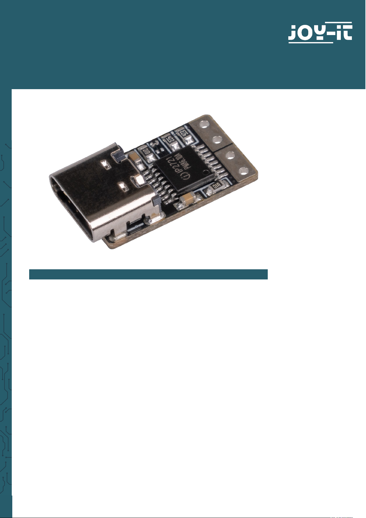
All three items have the same circuit board and dier only in the output
interface.
When using the modules, make sure to use a suicient cable
cross-section.
To use the modules as intended, you need a USB-PD-capable power
supply unit.
Page 2
2. INTERFACE
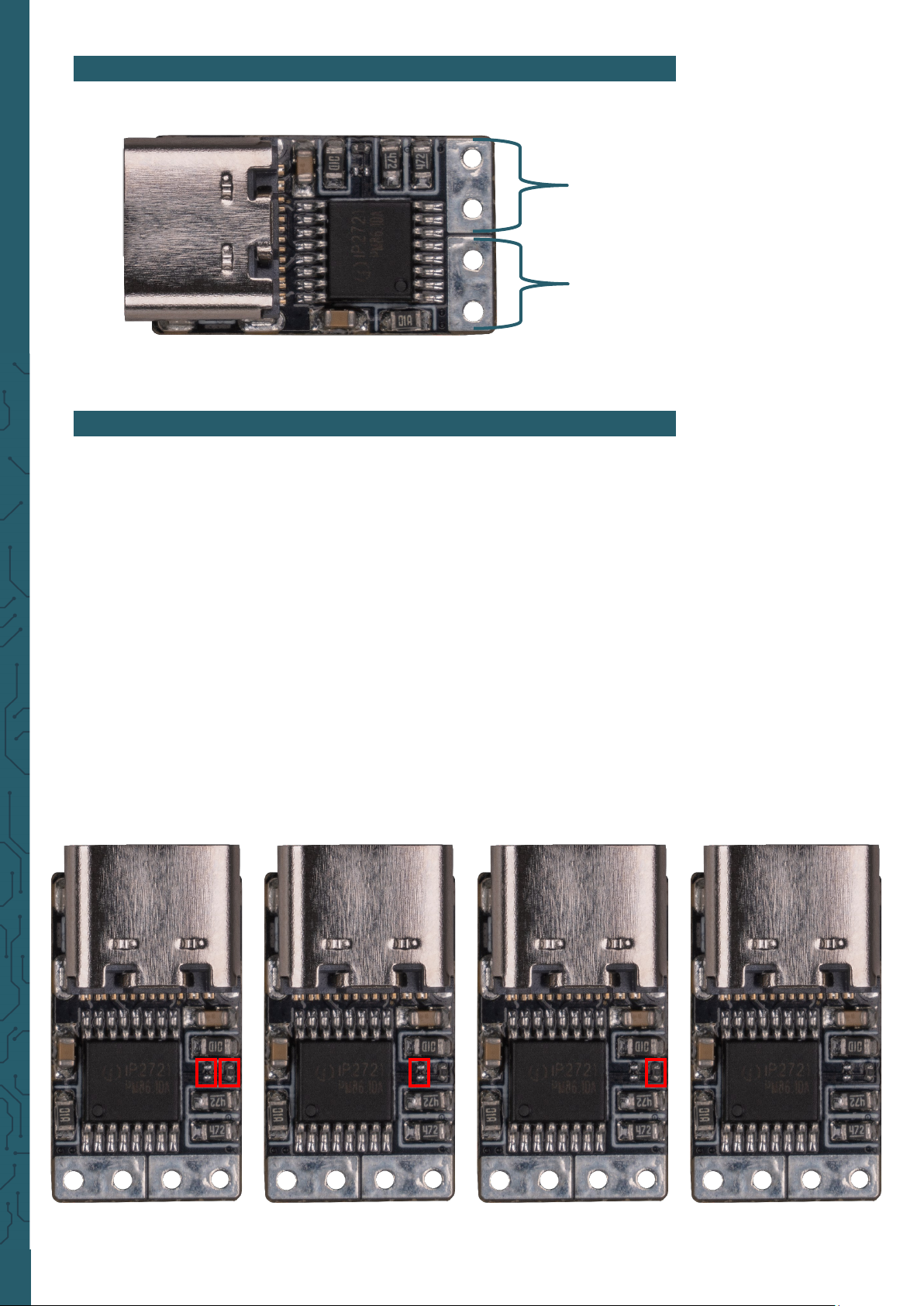
Connect your USB-PD trigger module to a USB-PD capable power supply
using the USB-C connector. These modules provide you with dierent
voltage modes. The mode can be changed by re-soldering a resistor.
Attention: Unsoldering the resistors is not easy for the unpractised due to
the very small size of the resistors (0.6 mm x 0.3 mm).
If both resistors are soldered, the output is set to 5 V.
If the resistor on the board on the le is soldered (USB-C points upwards),
the output is also set to 5 V.
If the resistor on the board on the right is soldered (USB-C points upwards),
the output is set to 20 V.
If no resistor is soldered, the output is set to 15 V.
The other voltage modes of 9 V and 12 V can only be achieved by an
appropriate power supply that outputs such voltage.
+
-
3. OPERATION
Both resistors
soldered = 5 V
Le resistor
soldered = 5 V
Right resistor
soldered = 20 V
No resistor
soldered = 15 V
Page 3

PR
4. OTHER INFORMATION
Our Information and Take-back Obligations according to the
Electrical and Electronic Equipment Act (ElektroG)
Symbol on Electrial and Electronic Products:
This crossed-out bin means that electrical and electronic products do not
belong into the household waste. You must hand over your old appliance
to a registration place. Before you can hand over the old appliance, you
must remove used batteries and replacement batteries which are not
enclosed by the device.
Return Options:
As the end user, you can hand over your old appliance (which has
essentially the same functions as the new one bought with us) free of
charge for disposal with the purchase of a new device.
Small devices, which do not have outer dimensions bigger than 25 cm
can be handed in for disposal independently of the
purchase of a new product in normal household quantities.
1. Possibility of return at our company location during our opening
hours
SIMAC Electronics GmbH, Pascalstr. 8, D-47506 Neukirchen-Vluyn
2. Possibility of return nearby
We will send you a parcel stamp with which you can send us your old
appliance free of charge. For this possibility, please contact us via e-mail
at service@joy-it.net or via telephone.
Information about Package:
Please package your old appliance safe for transport. Should you not
have suitable packaging material or you do not want to use your own
material, you can contact us and we will send you an appropriate
package.
5. SUPPORT
If any questions remained open or problems may arise aer your
purchase,we are available by e-mail, telephone and ticket support
system to answer these.
E-Mail: service@joy-it.net
Ticket-system: http://support.joy-it.net
Telephone: +49 (0)2845 98469 – 66 (10 - 17 o'clock)
For further information visit our website:
www.joy-it.net
Published: 22.10.2021
www.joy-it.net
SIMAC Electronics GmbH
Pascalstr. 8, 47506 Neukirchen-Vluyn
 Loading...