

Page 1

Introduction: The BBC micro:bit interface for Fischertechnik gives an
alternative to control motors and components in the Fischertechnik range.
Designed to run from a 9V PP3 battery (as used in Fischertechnik kits) the
PCB produces a regulated 3V supply to power the BBC micro:bit. The board
also includes a power switch to turn on and off the supply.
There are plated holes for using the Fischertechnik plugs to connect
components from the Fischertechnik kits to the PCB. The PCB has been
designed to slot onto the Fischertechnik base plate to give ease of access to
the additional circuitry. See dimensions for Fischertechnik base plate grid
hole counts.
:CREATE BBC micro:bit interface for Fischertechnik
www.kitronik.co.uk/5656
Pinout
P0 Input/Output pin
P1 Input/Output pin
P5/SW A Switch A pin
P11/SW B Switch B pin
P8 Motor 1 control line
P12 Motor 1 control line
P2 Motor 2 control line
P16 Motor 2 control line
Connections: There are 2
Input/Output pins and 2 switch
inputs, each paired with a 0V
connection
2 pairs of motor connections that
can drive a motor both clockwise
and counter-clockwise. The
corresponding pins to the BBC
micro:bit are labelled in the table
and on the PCB.
Inserting a BBC micro:bit:
The board has been designed so that
the BBC micro:bit can plug directly
into the edge connector on the
Motor Board. The BBC micro:bit can
be inserted facing either direction.
Layout & Dimensions:
NOTE: PCB is 17.2mm in height
BBC micro:bit
Edge
Connector
Motor 2
Power Connection
Power Switch
66 mm
79 mm
I/O pin
with paired
0V pin
LED
status
indicator
Motor 1
x4 Fischertechnik
base plate
keyslots
45mm / 4 grid holes
60mm / 5 grid
holes
15mm / 2 grid holes
23mm
Motor
Direction
LEDs
Page 2
:CREATE BBC micro:bit interface for Fischertechnik
www.kitronik.co.uk/5656
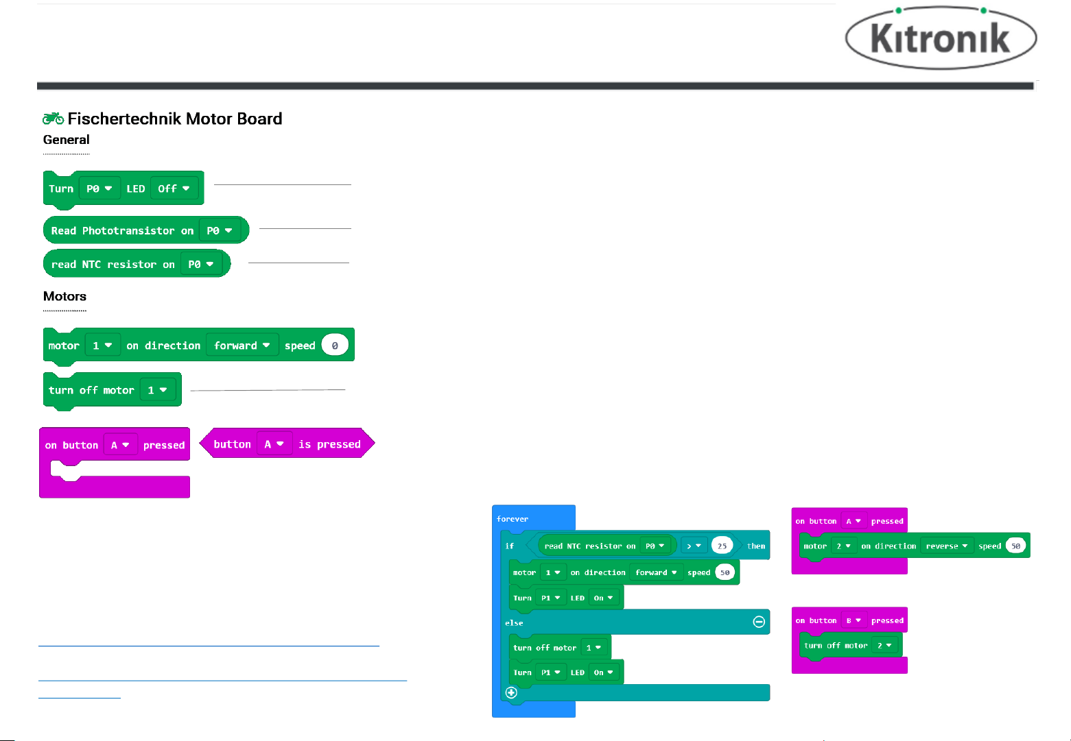
Software:
Custom MAKECODE blocks have been created for driving the electrical components supplied in the
Fischertechnik Electronics kit. These include switches, LED, Phototransistor and NTC resistor.
Motor On – the block allows the user to select which motor, the direction required and the speed of the motor
(between 0 and 100)
NTC Block – measures the temperature in Celsius and returns a number. It is possible to select either P0 or P1
Phototransistor Block – take a voltage reading from the phototransistor, select either P0 or P1. returns a value
between 0 and 255
LED Block – Connect the LED to either P0 or P1 from the selection and choose to either turn it on or off
Motor Off – select which motor to stop.
Example Code:
The example code reads the temperature of the NTC resistor (on P0)
and turns on an LED on P0, and Motor 1 when over 25 degrees C.
When below 25 degrees C, the LED and Motor 1 are turned off.
Pressing Button A and Button B will start and stop Motor 2.
The Makecode blocks and microPython example code are available at:
https://github.com/KitronikLtd/pxt-kitronik-fischertechnik
and
https://github.com/KitronikLtd/micropython-microbit-kitronikfischertechnik
Buttons – inputs SW A and SW B on the board link with using the standard button press blocks in Makecode.
 Loading...