

Page 1
MEGA2560
Microcontroller Learning - Kit
Page 2

www.joy-it.net
Pascalstr. 8 47506 Neukirchen-Vluyn
ME
1. TABLE OF CONTENT
1. Table of content
2. General information
3. Soware installation
4. Resistors
5. Lessons
1. Lesson : Hello World
2. Lesson : Flashing LED
3. Lesson : PWM light control
4. Lesson : Traic light
5. Lesson : LED hunting eect
6. Lesson : Key-controlled LED
7. Lesson : Responder experiment
8. Lesson : Active buzzer
9. Lesson : Passive buzzer
10. Lesson : Reading the analog value
11. Lesson : Photo resistor
12. Lesson : Flame sensor
13. Lesson : Tilt sensor
14. Lesson : 1-digit LED segment display
15. Lesson : 4-digits LED segment display
16. Lesson : LM35 temperature sensor
17. Lesson : 74HC595 shi register
18. Lesson : RGB LED
19. Lesson : Infrared remote control
20. Lesson : 8x8 LED Matrix
6. Other information
7. Support
Page 3

www.joy-it.net
Pascalstr. 8 47506 Neukirchen-Vluyn
1. GENERAL INFORMATION
Dear customer,
Thank you very much for choosing our product. In the following, we will
show you what has to be observed during commissioning and use.
Should you encounter any unexpected problems during use, please feel
free to contact us.
Technical data
Our board is a high-quality replica and compatible to the Arduino Mega
2560 but it is explicitly not an original Arduino.
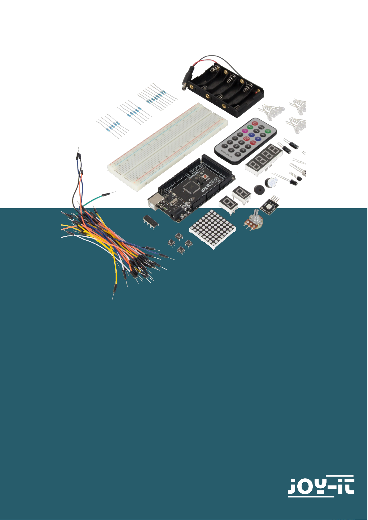
The Mega 2560 is the right microcontroller board for those who want to
get into the programming world quickly and easily as possible. This set
guides you through a variety of projects. Its ATMega2560 microcontroller
oers you enough power for your ideas and projects. It measures 101.52 x
53.3 mm and has with 54 digital inputs and outputs and 16 analog inputs
many possibilities to connect.
Model ard_Mega2560R3
Microcontroller ATMega2560
Input voltage 7 - 12 V
Maximum input voltage 6 - 20 V
Digital IO 54 (14 with PWM)
Analog IO 16
DC current IO 40 mA
DC current 3,3 V 50 mA
Memory 256 kB (8 kB for Bootloader)
SRAM 8 kB
EEPROM 4 kB
Clock Speed 16 MHz
Dimensions 101.52 x 53.3 mm
Page 4
www.joy-it.net
Pascalstr. 8 47506 Neukirchen-Vluyn
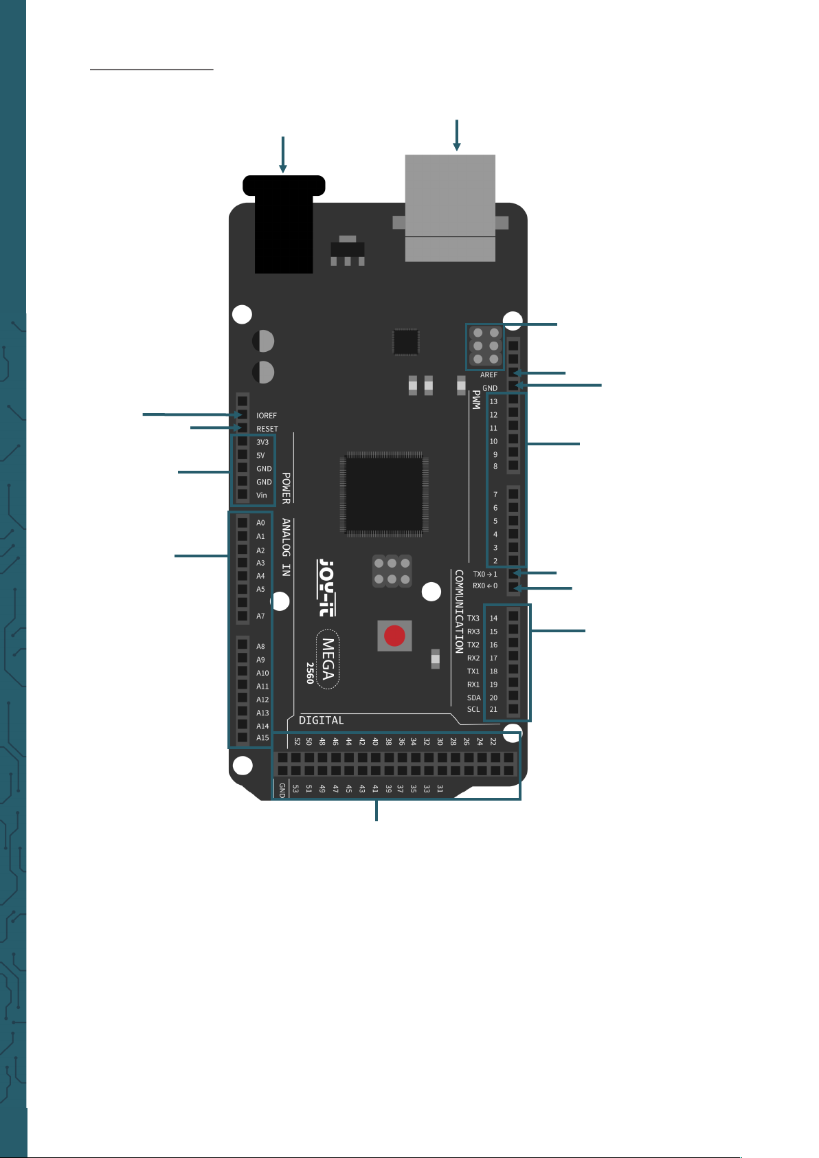
Pin assignment
Voltage regulator
USB-B-Port
ICSP for USB
AREF
GND
PWM
Interface
TXO
RXO
Communication
interface
Digital
I/O Pins
Analog
Inputs
Power supply
Reset
IOREF
Page 5
www.joy-it.net
Pascalstr. 8 47506 Neukirchen-Vluyn
3. SOFTWARE INSTALLATION
In order to start programming the Joy-IT ard_Mega2560R3, a develop-
ment environment and the drivers for the corresponding operating system must first be installed on the computer.
The Arduino IDE (which you can download here), which is available as an
OpenSource soware under the GPLv2 and published by the Arduino
manufacturer. It is aimed at beginners from concept and structure. It is
fully compatible with the Joy-IT ard_Mega2560R3 and contains the programming environment as well as the necessary drivers to get started
right away.
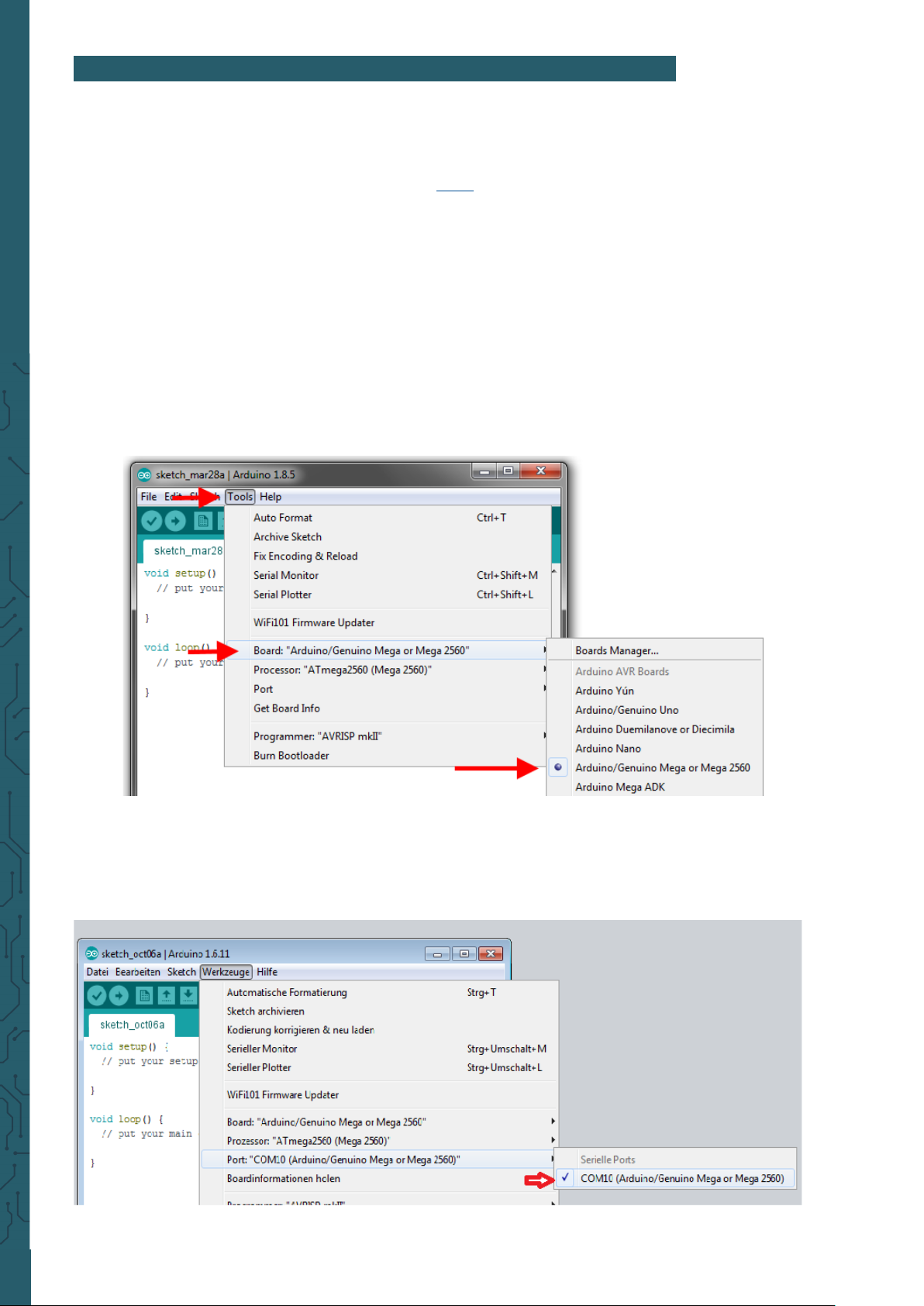
Aer installing the soware, the corresponding microcontroller board
must be set up in the programming environment. To do this, follow the
following two steps:
1. Under
Tools → Board
muss
Arduino/Genuino Mega or Mega 2560
must be selected.
2. Under
Tools → Port
then select the port which is marked with
Arduino/Genuino Mega or Mega 2560
.
Page 6

www.joy-it.net
Pascalstr. 8 47506 Neukirchen-Vluyn
4. RESISTORS
In this set there are three dierent resistors 220 Ω, 1 kΩ and 10 kΩ. On re-
sistors there is a colour coding which can be used to calculate or detect
the resistance if it cannot be measured with a multimeter.
In this chapter you will learn how to calculate this resistance in order to
better perform the following lessons, because you need to be able to
identify the dierent resistances in order to correctly reproduce the setups.
First you have to measure the number of rings on the resistor, because
resistors can have four or five rings. In this set, the resistors have 5 rings,
which give you a more accurate indication of the resistance value than
with 4 rings.
Now you have to determine which ring is the first one. This first ring can
be identified by the fact that it is further away from the end of the body
than the last ring.
You can now calculate the resistance value with a formula. If there are 5
rings, the first 3 rings serve as resistance counters and the fourth as
multiplier, which calculates the total resistance value. The fih ring is the
tolerance ring, which calculates the deviation of resistance value. With
four rings, the third ring is omitted as a resistance counter and then
serves as a multiplier. The fourth ring is then the tolerance ring.
The rings have a specific colour code, where each colour has a
has a certain value. In the following, you see the colour table for 5 rings:
1. Ring 2.Ring 3. Ring 4. Ring
(Multiplier)
5. Ring
(Tolerance)
Ring colour
Black 0 0 0 - -
Brown 1 1 1 x 10 1 %
Red 2 2 2 x 100 2%
Orange 3 3 3 x 1.000 -
Yellow 4 4 4 x 10.000 -
Green 5 5 5 x 100.000 0,5 %
Blue 6 6 6 x 1.000.000 0,25 %
Purple 7 7 7 x 10.000.000 0,1 %
Grey 8 8 8 - -
White 9 9 9 - -
Gold - - - x 0,1 5 %
Silver - - - x 0,01 10 %
Page 7
www.joy-it.net
Pascalstr. 8 47506 Neukirchen-Vluyn
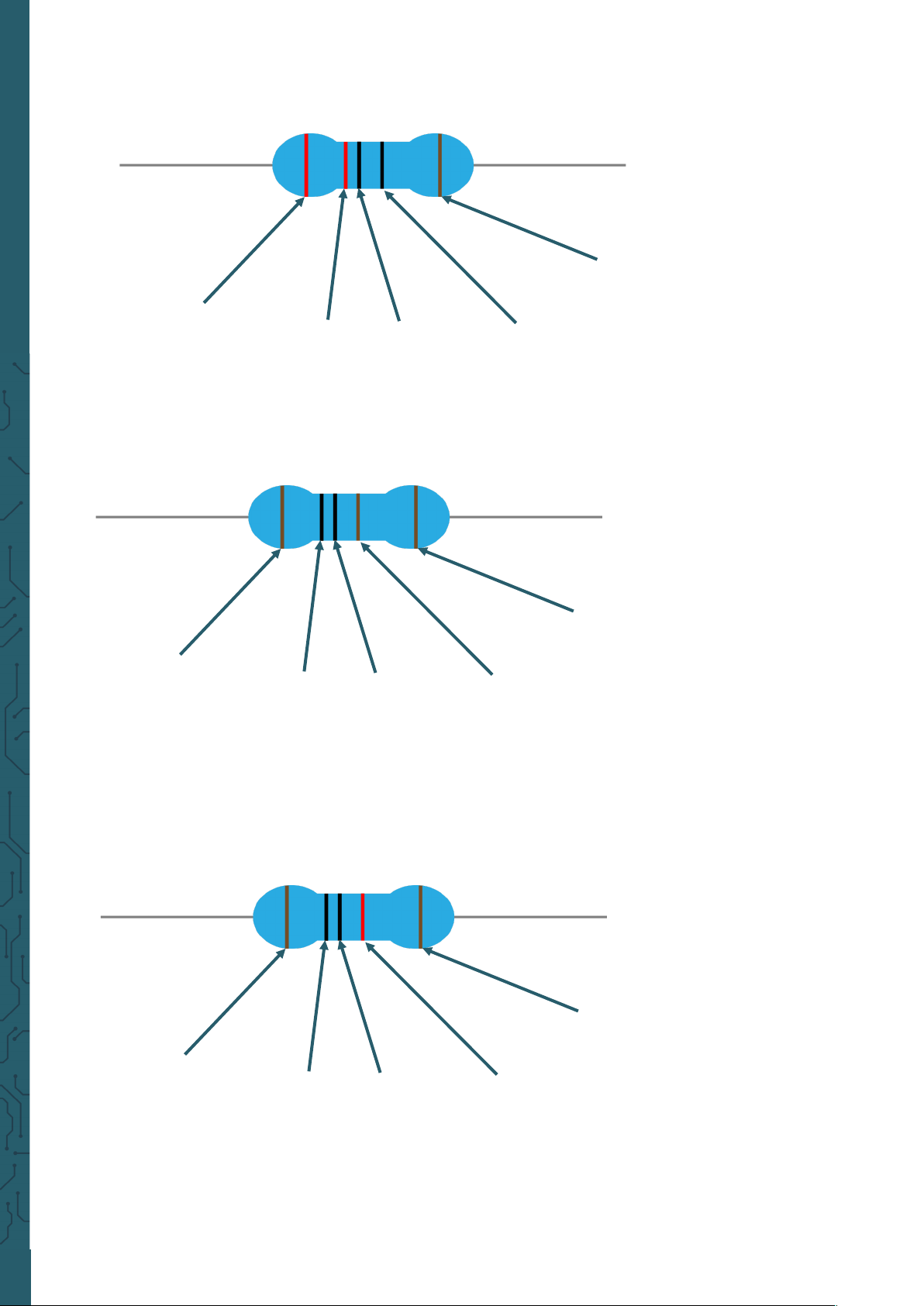
If we now look at our resistances, we cann quickly calculate their value.
Let's start with the 220 Ω resistance
1. Ring:
Red : 2
2. Ring:
Red : 2
3. Ring:
Black : 0
4. Ring (Multiplier):
Black : -
5. Ring (Tolerance):
Brown : 1 %
Due to the fact that the multiplier has no value, the resistance can be
determined on 220 Ω with a tolerance of 1%, which this resistance can
vary.
1. Ring:
Brown: 1
2. Ring:
Black : 0
3. Ring:
Black : 0
4. Ring (Multiplier):
Brown: x 10
5. Ring (Tolerance):
Brown: 1 %
The first three rings give the first value of 100, which is calculated by
means of the multiplier (x 10) to the resistance value of 1000 Ω. This can
also be converted to 1 kΩ. So this has resistor a resistance value of 1 kΩ
with a tolerance of 1 %.
1. Ring:
Brown: 1
2. Ring:
Black : 0
3. Ring:
Black : 0
4. Ring (Multiplier):
Red : x 100
5. Ring (Tolerance):
Brown: 1 %
The first three rings result again in the first value of 100. By means of the
multiplier of x 100 the resistance value of 10.000 Ω is obtained, which can
be converted into 10 kΩ. Also this resistor has again a tolerance of 1 %.
Page 8
www.joy-it.net
Pascalstr. 8 47506 Neukirchen-Vluyn
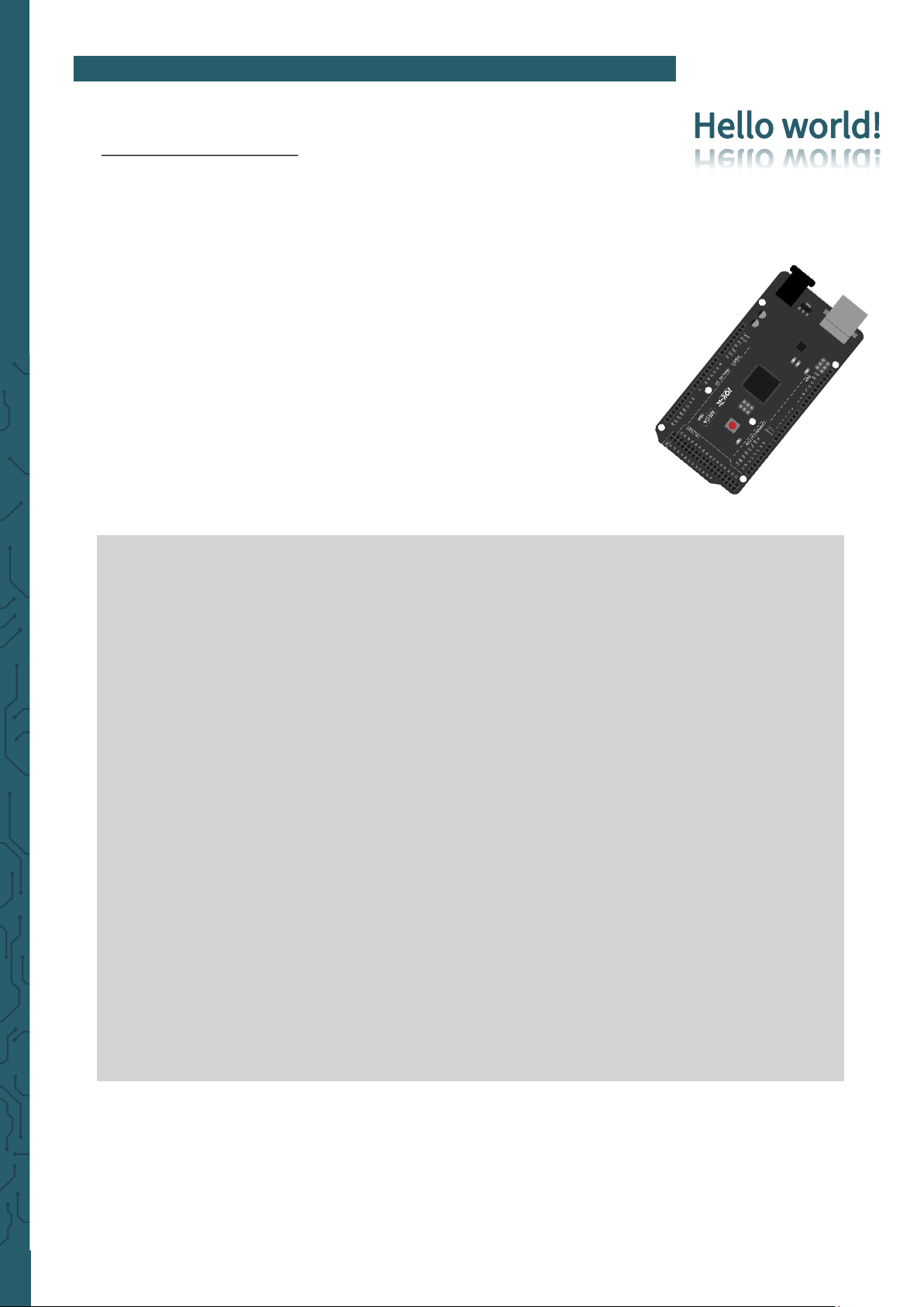
5. LESSONS
Lesson 1 : Hello world
We start with something simple. For this project you only need the board
and a USB cable to start the lesson. This is a communication test for your
Mega2560 and your PC, and a basic project for your first try in the
Arduino world!
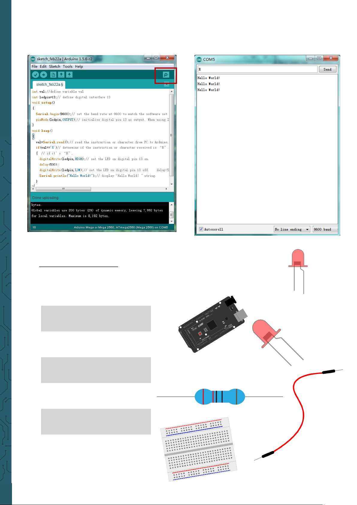
Once the installation of the drivers is complete, open the Arduino
soware and write a code that will allow the Mega2560 to display
Hel-
lo World!
under your instructions. Of course, you can also write a code
that will allow the Mega2560 to display
Hello World!
repeatedly with-
out prompting. A simple
if()
statement will do this. We can instruct the
LED on pin 13 to blink first and then display Hello World! aer the Arduino gets the command to do so.
int val; // defines the variable “Val”
int ledpin=13; // defines the digital interface 13
void setup() {
Serial.begin(9600);
// sets the baudrate to 9600 to fit the software configuration
pinMode(ledpin,OUTPUT); // sets the digital pin 13 to output
}
void loop() {
val=Serial.read();
if(val=='R') { // checks if the character is a R.
// if so:
digitalWrite(ledpin,HIGH); // turns on LED
delay(500);
digitalWrite(ledpin,LOW); // turns off LED
delay(500);
Serial.println("Hello World!"); // Shows „Hello World!”.
}
}
Page 9
www.joy-it.net
Pascalstr. 8 47506 Neukirchen-Vluyn
Click on the serial monitor and add R , then the LED on the board will
light up and your PC will receive the information
Hello World!
from the
Arduino.
Lesson 2: Flashing LED
In the Hello World! program we have already encountered the LED. This
time we will connect an LED with one of the digital pins. The following
parts are needed:
Mega2560 board
1x
USB cable
1x
Red M5 LED
1x
220 Ω resistor
1x
Breadboard
1x
Jumper cable
2x
Page 10
www.joy-it.net
Pascalstr. 8 47506 Neukirchen-Vluyn
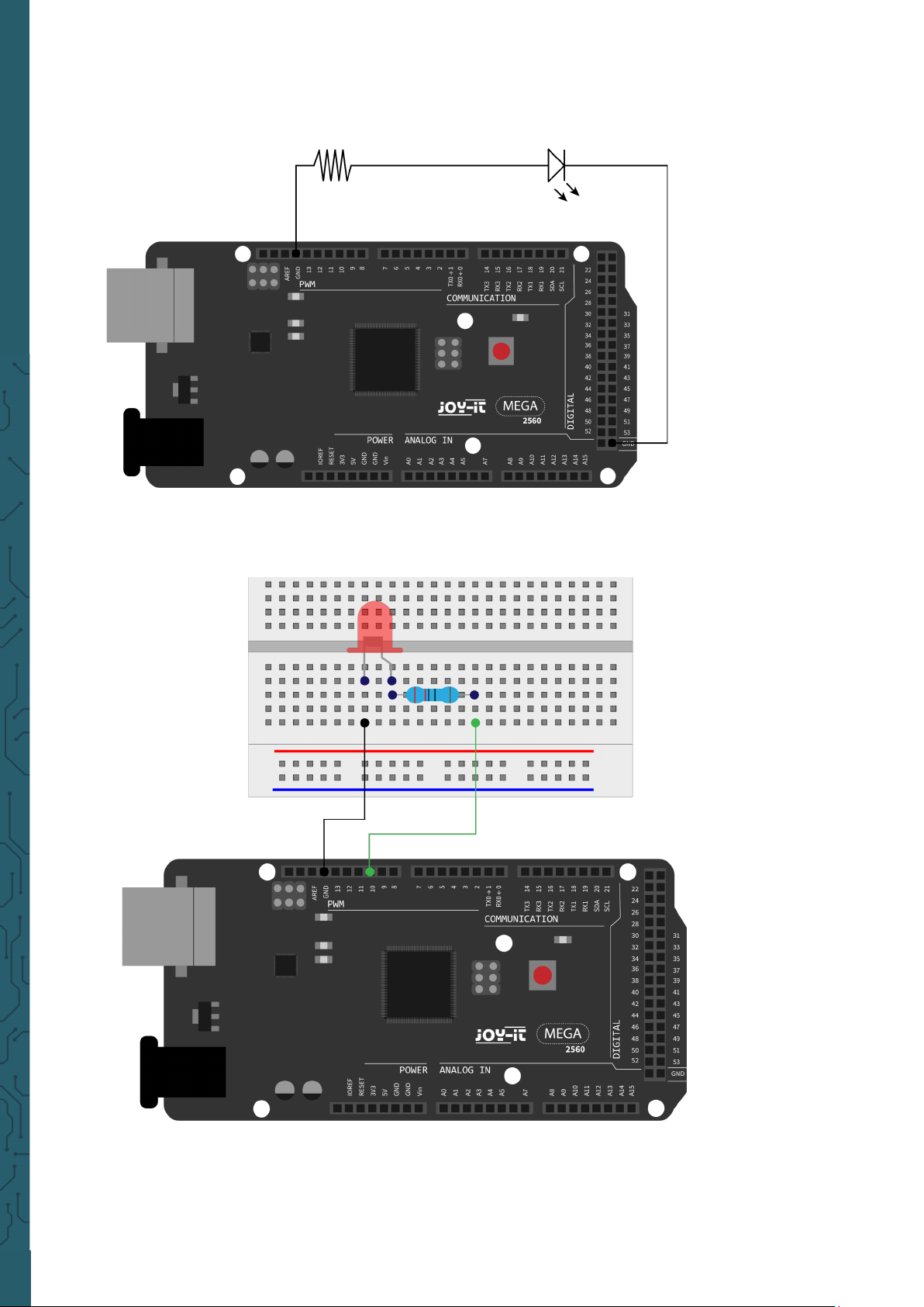
We follow the following wiring diagram. Here we use the digital pin 10.
We connect the LED with a 220 Ω resistor to avoid damage due to
excessive current.
Page 11
www.joy-it.net
Pascalstr. 8 47506 Neukirchen-Vluyn
int ledPin = 10; // defines Digital Pin 10.
void setup() {
pinMode(ledPin, OUTPUT); // defines pin to output
}
void loop() {
digitalWrite(ledPin, HIGH); // turns on led
delay(1000); // waits a second
digitalWrite(ledPin, LOW); // turns off led
delay(1000); // waits a second
}
Aer uploading the program you will se the LED which is connected to pin
10 , light up every second.
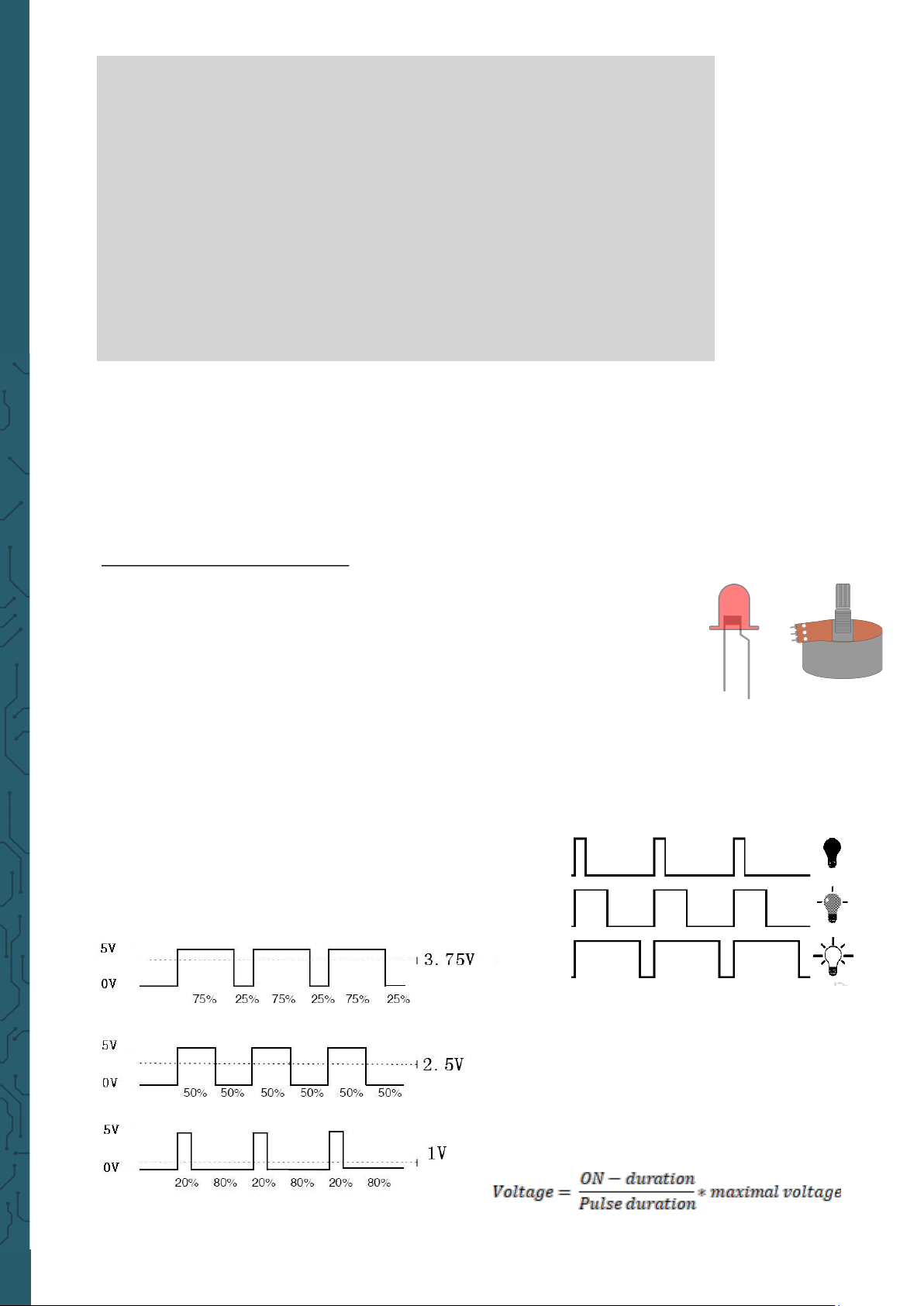
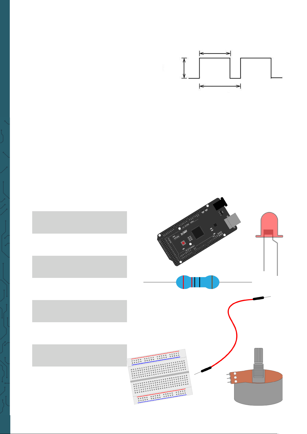
Lesson 3: PWM light control
PWM (short for Pulse Width Modulation) is a technique used to encode
analog signal levels into digital ones. A computer is not capable of outputting analog voltage. It can only output digital voltage with values like
0 V or 5 V. Therefore a high resolution counter is used to output a specific
analog signal level by encoding the utilization level by modulating PWM .
The PWM signal is also digitized, because to each time the power supply
is either 5 V (on) or 0 V (o).
The voltage or current is supplied to the analog load (the device that consumes the energy) by repeated pulse sequences, by constantly switching
between the on and o states. The value of the output voltage is determined by the on and o states.
Page 12
www.joy-it.net
Pascalstr. 8 47506 Neukirchen-Vluyn
There are many applications for PWM: regulation of lamp brightness, regulation of motor speed, etc. .
These are the three basic parameters of PWM:
Mega2560 board
1x
USB cable
1x
Red M5 LED
1x
220 Ω resistor
1x
Breadboard
1x
Jumper cable
6x
1x
Potentiometer
1. The amplitude of the pulse width
(minimum / maximum)
2. The pulse period
(The mutual pulse rate in one second)
3. The voltage level
(like: 0 - 5 V)
There are 6 PWM interfaces on the Mega2560: digital pins 3, 5, 6, 9, 10 and
11.
In previous experiments we have got to know the key-controlled LED,
where we used a digital signal to generate a digital pin.
Now we will use a potentiometer to control the brightness of the LED. We
need for this:
Height
Width
Cycle
Page 13
www.joy-it.net
Pascalstr. 8 47506 Neukirchen-Vluyn
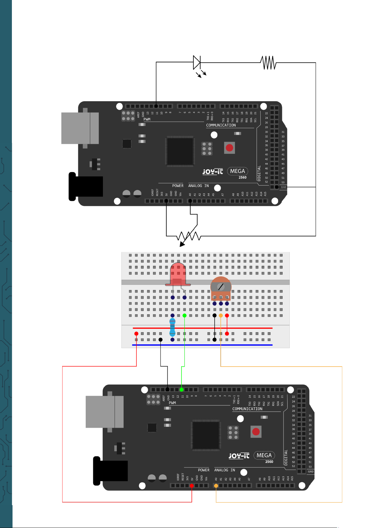
The input of the potentiometer is analog, so we connect it to the analog
port. We connect the LED to the PWM port. A other PWM signal can
regulate the brightness of the LED.
Page 14
www.joy-it.net
Pascalstr. 8 47506 Neukirchen-Vluyn
In this experiment we will read the analog value of the potentiometer and
assign the value to the PWM port, so that a corresponding change in the
brightness of the LED can be observed. We will also display the analog
value on the screen.
int potpin = 0; // Initialises analog Pin 0
int ledpin = 11; // Initialises digital Pin 11 (PWM Output)
int val = 0; // Saves the Sensors Value
void setup() {
pinMode(ledpin,OUTPUT); // defines digital Pin 11 to „Output“
Serial.begin(9600); // Sets Baudrate to 9600
}
void loop() {
val = analogRead(potpin);
// reads the Analog-Value of the sensor and assigns it to „Val“
Serial.println(val); // shows the value of „Val“
analogWrite(ledpin,val/4);
// turns on the LED and sets the brightness (Max. Value: 255)
delay(10); // Waits 0,01 Seconds
}
Aer transmission of the program and when moving the potentiometer,
we can observe changes in the displayed values. We can also see an
obvious change in LED brightness.
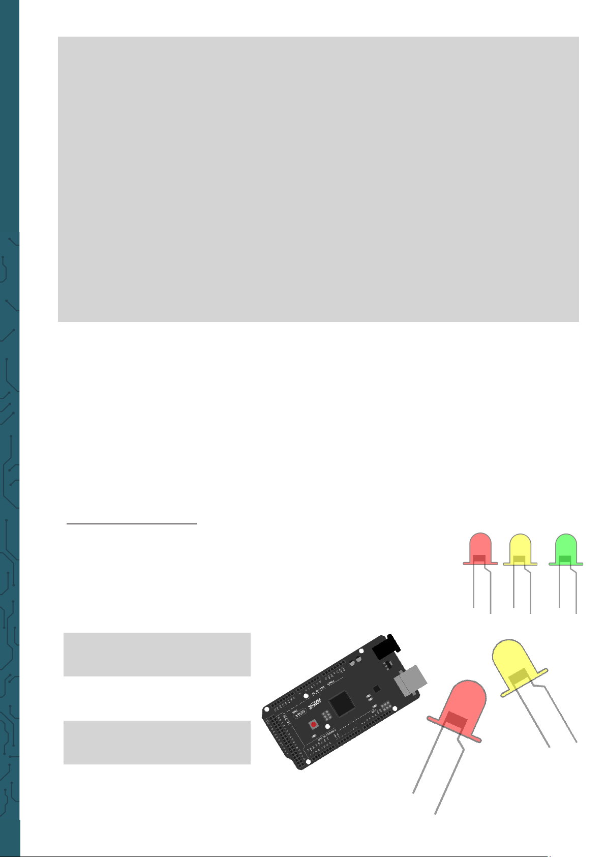
Lesson 4: Traic lights
In the previous program we did the flashing LED experiment with only
one LED. Now it is time to do a more complicated experiment: Traic
lights.
Actually these two experiments are very similar. In this experiment we
will use 3 LEDs with dierent colors, while in the last one only one LED
was used. We need for this:
1x
Mega2560 board
1x
USB cable
1x
Red M5 LED
1x
Yellow M5 LED
Page 15
www.joy-it.net
Pascalstr. 8 47506 Neukirchen-Vluyn
1x
Green M5 LED
3x
220 Ω resistor
1x
Breadboard
4x
Jumper cable
Page 16

www.joy-it.net
Pascalstr. 8 47506 Neukirchen-Vluyn
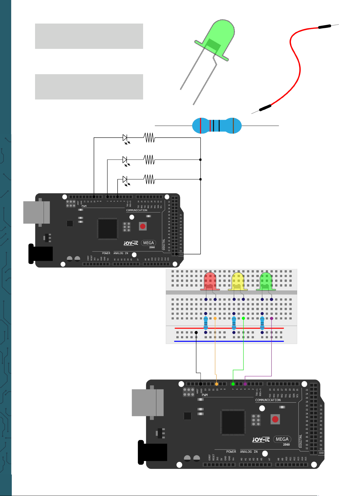
Since this is a situation of traic lights, the lighting time of each
individual LED should be exactly the same as in a real traic light. In this
program we will use the Arduino delay function to control the delay time.
int redled =10; // Initialises digital Pin 8
int yellowled =7; // Initialises digital Pin 7
int greenled =4; // Initialises digital Pin 4
void setup() {
pinMode(redled, OUTPUT); // Sets Pin with red LED to „Output“
pinMode(yellowled, OUTPUT);// Sets Pin with yellow to „Output“
pinMode(greenled, OUTPUT);// Sets Pin with green LED to „Output“
}
void loop() {
digitalWrite(greenled, HIGH); // turns on green leed
delay(5000); // Waits 5 Seconds
digitalWrite(greenled, LOW); // turns off green LED
for(int i=0;i<3;i++) { // flashes 3x
delay(500);
digitalWrite(yellowled, HIGH); // turns on the yellow LED
delay(500);
digitalWrite(yellowled, LOW); // turns on the yellow LED
}
delay(500);
digitalWrite(redled, HIGH); // turns on the red LED
delay(5000);
digitalWrite(redled, LOW); // turns on the red LED
}
Once the file has been uploaded, the traic lights are visible. The green
light will stay on for 5 seconds and then turn o. Then the yellow light will
flash 3 times and then the red light for 5 seconds, so that a circuit is for-
med.
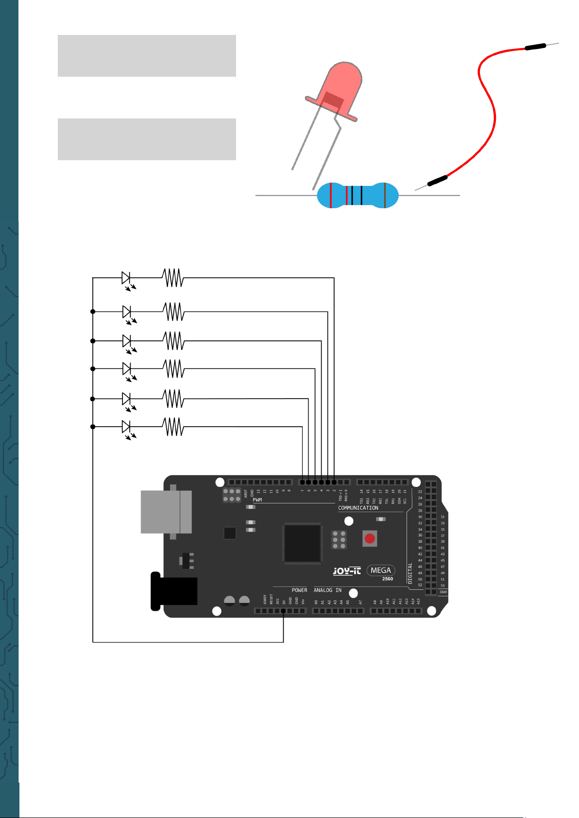
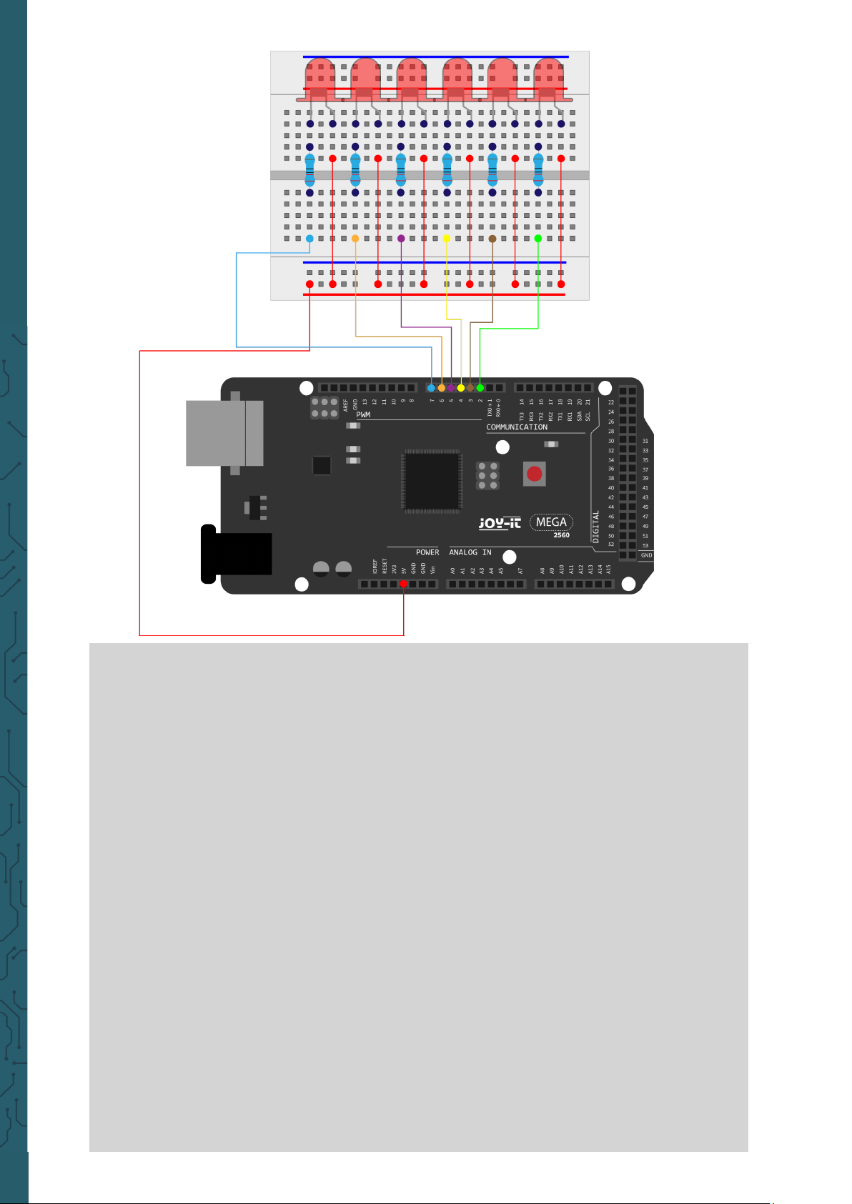
Lesson 5: LED hunting eect
We oen see billboards, which are equipped with coloured LEDs. These
change constantly to create dierent eects. In this experiment, a program is created which simulates the LED hunting eect. This is needed:
1x
Mega2560 board
1x
USB cable
Page 17
www.joy-it.net
Pascalstr. 8 47506 Neukirchen-Vluyn
6x
M5 LED
6x
220 Ω resistor
1x
Breadboard
13x
Jumper cable
Page 18
www.joy-it.net
Pascalstr. 8 47506 Neukirchen-Vluyn
int BASE = 2 ; // The I/O pin for the first LED
int NUM = 6; // Amount of LEDs
void setup() {
for (int i = BASE; i < (BASE + NUM); i ++) {
pinMode(i, OUTPUT); // Set I/O pins as output
}
}
void loop() {
for (int i = BASE; i < (BASE + NUM); i ++){
digitalWrite(i, LOW); // Sets I/O pins to "low"
// switches on the LEDs one after the other
delay(200); // delay
}
for (int i = BASE; i < (BASE + NUM); i ++) {
digitalWrite(i, HIGH); // Sets I/O pins to "high"
// switches off the LEDs one after the other
delay(200); // delay
}
}
Page 19
www.joy-it.net
Pascalstr. 8 47506 Neukirchen-Vluyn
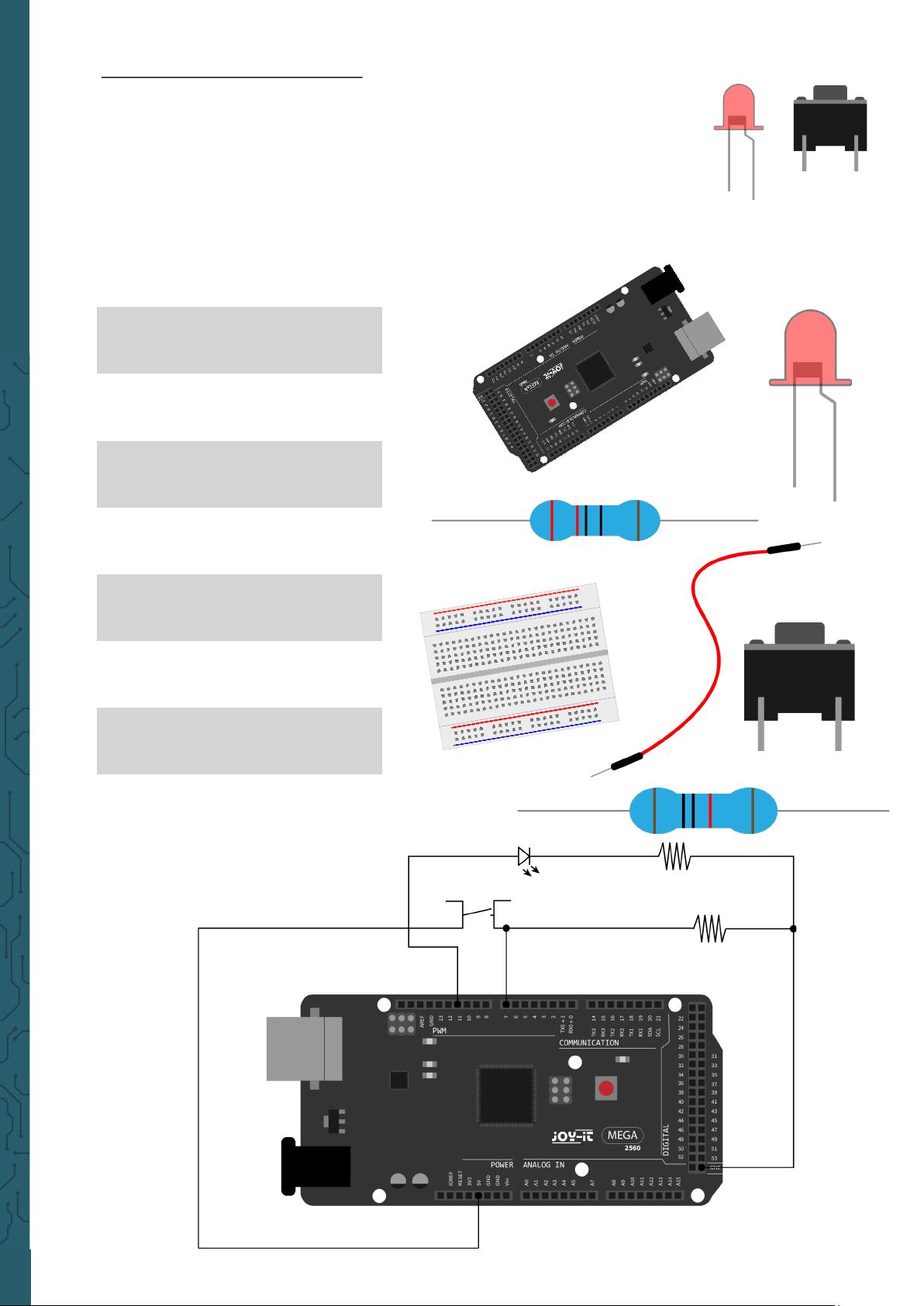
Lesson 6: Key-controlled LED
I/O-Port is an interface, which can be used as input and output. So far,
we've only used it as the output. In this experiment we will try to use the
input to read the output value of the connected device. We will use a key
as input and a LED as output to get a better understanding of the I/O
functions.Key switches, which many people probably know, have a
switching value (digital value). When the switch is pressed, the circuit
closes and is in a conducting state.
For this we need:
1x
Mega2560 board
1x
USB cable
1x
Red M5 LED
1x
220 Ω resistor
1x
10 kΩ resistor
1x
Key switch
1x
Breadboard
6x
Jumper cable
Page 20

www.joy-it.net
Pascalstr. 8 47506 Neukirchen-Vluyn
When the key is pressed, the LED is on, otherwise it remains o. The
simple principle of this experiment is oen used in a variety of circuits
and electrical devices.
220 Ω
10 kΩ
int BASE = 2 ; // I/O Pin for the first LED
int NUM = 6; // Amount of LEDs
void setup() {
for (int i = BASE; i < (BASE + NUM); i ++) {
pinMode(i, OUTPUT); // Sets I/O Pins to output
}
}
void loop() {
for (int i = BASE; i < (BASE + NUM); i ++) {
digitalWrite(i, LOW); // Set I/O Pin to „low“
// turns on leds one by one
delay(200); // delay
}
for (int i = BASE; i < (BASE + NUM); i ++) {
digitalWrite(i, HIGH); // Sets I/O Pin to „high“
// turns off led one by one
delay(200); // delay
}
}
Page 21

www.joy-it.net
Pascalstr. 8 47506 Neukirchen-Vluyn
Lesson 7: Responder experiment
In this lesson there are three button switches and a reset button, which
control the 3 corresponding LEDs by means of 7 digital I/O pins. For this
you need:
1x
Mega2560 board
1x
USB cable
7x
220 Ω Widerstand
1x
Red M5 LED
1x
Yellow M5 LED
1x
Green M5 LED
4x
Key switch
1x
Breadboard
13x
Jumper cable
Page 22

www.joy-it.net
Pascalstr. 8 47506 Neukirchen-Vluyn
int redled=8; // Pin for red LED
int yellowled=7; // Pin for yellow LED
int greenled=6; // Pin for green LED
int redpin=5; // Pin for red key
int yellowpin=4; // Pin for yellow key
int greenpin=3; // Pin for green key
int restpin=2; // Pin for reset pin
int red;
int yellow;
int green;
void setup() {
pinMode(redled,OUTPUT);
pinMode(yellowled,OUTPUT);
pinMode(greenled,OUTPUT);
pinMode(redpin,INPUT);
pinMode(yellowpin,INPUT);
pinMode(greenpin,INPUT);
}
Page 23

www.joy-it.net
Pascalstr. 8 47506 Neukirchen-Vluyn
void loop(){ //Repeatedly reads the pins of the keys
red = digitalRead(redpin);
yellow = digitalRead(yellowpin);
green = digitalRead(greenpin);
if(red==LOW)RED_YES();
if(yellow==LOW)YELLOW_YES();
if(green==LOW)GREEN_YES();
}
void RED_YES(){// Executes the code until red LED is on
// ends the cycle when the reset button is pressed
while(digitalRead(restpin)==1){
digitalWrite(redled,HIGH);
digitalWrite(greenled,LOW);
digitalWrite(yellowled,LOW);
}
clear_led();
}
void YELLOW_YES(){// Executes the code until yellow LED is on
// ends the cycle when the reset button is pressed
while(digitalRead(restpin)==1){
digitalWrite(redled,LOW);
digitalWrite(greenled,LOW);
digitalWrite(yellowled,HIGH);
}
clear_led();
}
void GREEN_YES() // Executes the code until green LED is on
// ends the cycle when the reset button is pressed
{
while(digitalRead(restpin)==1){
digitalWrite(redled,LOW);
digitalWrite(greenled,HIGH);
digitalWrite(yellowled,LOW);
}
clear_led();
}
void clear_led(){ // all LEDs off
digitalWrite(redled,LOW);
digitalWrite(greenled,LOW);
digitalWrite(yellowled,LOW);
}
Page 24

www.joy-it.net
Pascalstr. 8 47506 Neukirchen-Vluyn
Make sure you add both pieces of code in your sketch to the Arduino IDE.
When a button is pressed, the corresponding LED is switched on. When
the reset button is pressed, the corresponding LED is switched o again.
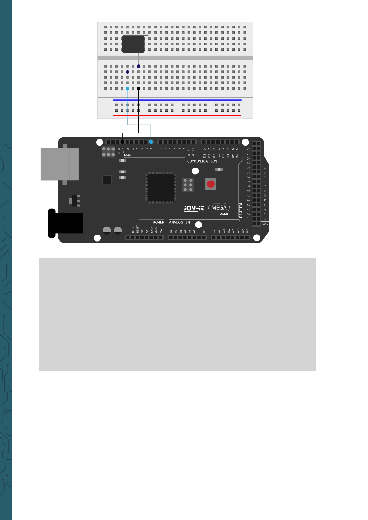
Lesson 8: Active buzzer
Active buzzers are used in computers, printers, alarm clocks, electric toys
etc. as a noise-emitting element. It has an internal vibration source. When
connected to a 5V power supply, it can buzz repeatedly.
This is required:
1x
Mega2560 board
1x
USB cable
1x
Active buzzer
(with sticker)
1x
Breadboard
2x
Jumper cable
Page 25
www.joy-it.net
Pascalstr. 8 47506 Neukirchen-Vluyn
The project is completed aer the transfer of the program. If the buzzer is
supplied with power aer the transfer, it will be making noises.
int buzzer=8;
// Initialize digital I/O pin, which controls the buzzer
void setup() {
pinMode(buzzer,OUTPUT); // set pin as "output"
}
void loop() {
digitalWrite(buzzer, HIGH); // makes noises
}
Page 26

www.joy-it.net
Pascalstr. 8 47506 Neukirchen-Vluyn
Lesson 9: Passive buzzer
With the Mega2560 many interactive projects are possible. The previous
projects have mainly dealt with LEDs, but a frequently used project is the
acoustic-optical display. For this a passive buzzer is used, which, in
contrast to the active buzzer, cannot activate itself.
The activation is done by a pulse frequency. Dierent frequencies result
in dierent tones of the buzzer. This can be used, for example, to reproduce the melody of a song.
This is required:
1x
Mega2560 board
1x
USB cable
1x
Passive buzzer
(without sticker)
1x
Breadboard
2x
Jumper cable
Page 27

www.joy-it.net
Pascalstr. 8 47506 Neukirchen-Vluyn
int buzzer=8; // I/O pin for buzzer
void setup() {
pinMode(buzzer,OUTPUT); // sets pin as output
}
void loop() {
unsigned char i,j; // defines variable
while(1){
for(i=0;i<80;i++) { // makes frequency sound
digitalWrite(buzzer,HIGH); // sound
delay(1); // 1ms delay
digitalWrite(buzzer,LOW); // no sound
delay(1); // 1ms delay
}
for(i=0;i<100;i++) { // makes frequency sound
digitalWrite(buzzer,HIGH); // sound
digitalWrite(buzzer,LOW); // no sound
delay(2); // 2ms delay
}
}
}
Page 28

www.joy-it.net
Pascalstr. 8 47506 Neukirchen-Vluyn
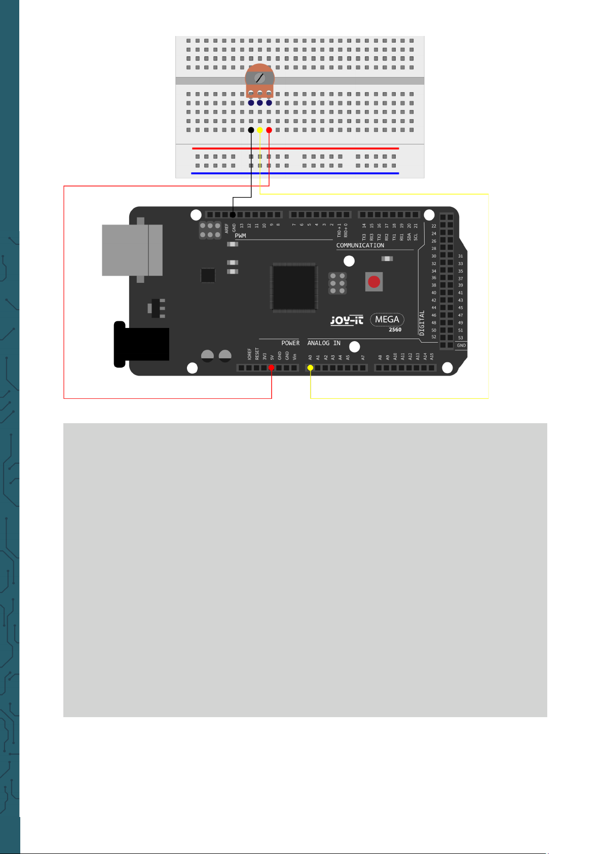
Lesson 10: Reading the analog value
This project deals with the analog interfaces of the Mega2560. An
analogRead()
command can read the value of the interface. Due to the
analog-to-digital conversion of the Mega2560 the read values are
between 0 and 1023.
To be able to read out the values, it is important to ensure the correct
baud rate (here: 9600). The baud rate of the computer should correspond
to the baud rate of the device. If you open the serial monitor of the
Arduino IDE, you can configure the baud rate in the lower right corner.
In this project, the set resistance value of a potentiometer is converted to
an analog signal and is then displayed on the screen.
This is required:
1x
Mega2560 board
1x
USB cable
1x
Potentiometer
1x
Breadboard
3x
Jumper cable
Page 29
www.joy-it.net
Pascalstr. 8 47506 Neukirchen-Vluyn
The read out values are displayed on the serial monitor.
int potpin=0; // sets pin for potentiometer to analog 0
int ledpin=13; // sets pin for led for pin 13
int val=0; // defines val
void setup() {
pinMode(ledpin,OUTPUT); // sets led pin as output
Serial.begin(9600); // sets baudrate to 9600
}
void loop() {
digitalWrite(ledpin,HIGH); // turns led on pin 13 on
delay(50); // waits 0.05 seconds
digitalWrite(ledpin,LOW); // turns led on pin 13 off
delay(500); // waits 0.05 seconds
val=analogRead(potpin); // reads analog value and assigns it to val
Serial.println(val); // displays val
}
Page 30

www.joy-it.net
Pascalstr. 8 47506 Neukirchen-Vluyn
Lesson 11: Photo resistor
A photoresistor is a resistor whose resistance varies depending on the
incident light intensity. It is based on the photoelectric eect of
semiconductors. When the incident light is intense, the resistivity is
reduced. If the incident light is weak, the resistance increases. Photo r
esistors are normally used for light measurement, light control and
photovoltaic conversion (converting the change of light into a change of
electricity). They are used in various light control circuits for example as
optical switches. In this project this eect is used to adjust an LED to the
current light intensity.
For this is needed:
1x
Mega2560 board
1x
USB cable
1x
Red M5 LED
1x
220 Ω resistor
1x
10 kΩ resistor
1x
Photo resistor
1x
Breadboard
5x
Jumper cable
Page 31

www.joy-it.net
Pascalstr. 8 47506 Neukirchen-Vluyn
int potpin=0; // Initialises analog Pin 0
int ledpin=11; // Initialises digital Pin 11
// output which regulates the led brightness
int val=0; // Initialises Variable „Val“
void setup() {
pinMode(ledpin,OUTPUT); // Set Pin 11 to output
Serial.begin(9600); // Set Baudrate to „9600“
}
void loop() {
val=analogRead(potpin);
// reads the sensors values and assigns it to val
Serial.println(val); // shows the values of val
analogWrite(ledpin,val); // turns on the led and sets the brightness
delay(10); // Waits 0,01 Seconds
}
220 Ω
10 kΩ
Page 32

www.joy-it.net
Pascalstr. 8 47506 Neukirchen-Vluyn
Lesson 12: Flame sensor
The flame sensor (infrared receiving triode) is specially designed for
robots used to find sources of flame. This sensor has a high sensitivity to
flames. The flame sensor is built on the principle that infrared radiation is
very sensitive to fire. It has a specially designed infrared pick-up tube to
detect fire, then to convert the brightness of the flame into a signal to
convert. These signals are then sent to the central processor and processed accordingly.
When the sensor approaches a fire, the analog voltage value. With a
multimeter you can check that the voltage is about 0.3 V if there is no fire
nearby. If there is a fire in the vicinity, the voltage is approx. 1.0 V. The
higher the voltage, the closer the fire.
For this project is required:
1x
Mega2560 board
1x
USB cable
1x
Flame sensor
1x
Active buzzer
(with sticker)
1x
10 kΩ resistor
1x
Breadboard
6x
Jumper cable
Page 33

www.joy-it.net
Pascalstr. 8 47506 Neukirchen-Vluyn
int flame=0; // analog pin 0 for sensor
int Beep=9; // digital pin 9 for buzzer
int val=0; // defines variable val
void setup() {
pinMode(Beep,OUTPUT); // sets buzzer pin as output
pinMode(flame,INPUT); // sets sensor pin as input
Serial.begin(9600); // sets baudrate to 9600
}
void loop() {
val=analogRead(flame); // reads the analog values of sensor
Serial.println(val); // prints analog values
if(val>=10) { // buzzer makes noises if value if over 10
// if necessary must be adjusted to the values of the sensor
digitalWrite(Beep,HIGH);
}
else{
digitalWrite(Beep,LOW);
}
delay(500);
}
Page 34

www.joy-it.net
Pascalstr. 8 47506 Neukirchen-Vluyn
Lesson 13: Tilt sensor
In this lesson, the tilt sensor acts as an on/o switch for an LED. The LED
is on when one end of the sensor is below the horizontal position. Using
the analog interface to which the tilt sensor is connected, you can check
the position of the sensor.
For this lesson you need:
Mega2560 board
1x
USB cable
1x
Red M5 LED
1x
220 Ω resistor
1x
Breadboard
1x
Jumper cable
5x
1x
Tilt sensor
1x
10 kΩ resistor
Page 35

www.joy-it.net
Pascalstr. 8 47506 Neukirchen-Vluyn
void setup() {
pinMode(8,OUTPUT); // sets pin 8 as output
}
void loop() {
int i; // defines variable i
while(1) {
i=analogRead(5);// reads voltage value from pin 5
if(i>512) { // if bigger than 512 (2.5 V)
digitalWrite(8,LOW); // switch LED on
}
else {
digitalWrite(8,HIGH); // switch LED off
}
}
}
220 Ω
10 kΩ
Page 36

www.joy-it.net
Pascalstr. 8 47506 Neukirchen-Vluyn
Lesson 14: 1-digit LED segment display
LED segment displays are widely used for displaying numerical
information. They are oen used for displays of electromagnetic ovens,
fully automatic washing machines, water temperature displays,
electronic watches, etc. The LED segment display is a semiconductor and
light emitting device. Its basic unit is an LED.
Depending on the wiring of the LED units, the LED segment display can be
divided into displays with common anode and displays with common
cathode. The common anode display combines all anodes of the LED
units into a common anode (COM). For the common anode display, the
common anode (COM) must be connected to + 5 V. If the cathode level of
a segment is low, the segment is on. If the cathode level of a segment is
high, the segment is o. For common cathode display, the common
cathode (COM) must be connected to GND. If the anode level of a
segment is high, the segment is on. If the anode level of a segment is low,
the segment is o.
For the following project is required:
1x
Mega2560 board
1x
USB cable
1x
1-digit
7-segment display
8x
220 Ω resistor
1x
Breadboard
12x
Jumper cable
Page 37

www.joy-it.net
Pascalstr. 8 47506 Neukirchen-Vluyn
Page 38

www.joy-it.net
Pascalstr. 8 47506 Neukirchen-Vluyn
// sets I/O pin for every segment
int a=7; // sets pin 7 for segments a
int b=6; // sets pin 6 for segments b
int c=5; // sets pin 5 for segments c
int d=10; // sets pin 10 for segments d
int e=11; // sets pin 11 for segments e
int f=8; // sets pin 8 for segments f
int g=9; // sets pin 9 for segments g
int dp=4; // sets pin 4 for segments dp
void digital_0(void) { // shows number 0
unsigned char j;
digitalWrite(a,HIGH);
digitalWrite(b,HIGH);
digitalWrite(c,HIGH);
digitalWrite(d,HIGH);
digitalWrite(e,HIGH);
digitalWrite(f,HIGH);
digitalWrite(g,LOW);
digitalWrite(dp,LOW);
}
void digital_1(void) { // shows number 1
unsigned char j;
digitalWrite(c,HIGH); // sets pin 5 high
digitalWrite(b,HIGH); // turns on segment b
for(j=7;j<=11;j++) // turns off other segments
digitalWrite(j,LOW);
digitalWrite(dp,LOW); // turns off segment dp
}
void digital_2(void) { // shows number 2
unsigned char j;
digitalWrite(b,HIGH);
digitalWrite(a,HIGH);
for(j=9;j<=11;j++)
digitalWrite(j,HIGH);
digitalWrite(dp,LOW);
digitalWrite(c,LOW);
digitalWrite(f,LOW);
}
Page 39

www.joy-it.net
Pascalstr. 8 47506 Neukirchen-Vluyn
void digital_3(void) { // shows number 3
digitalWrite(g,HIGH);
digitalWrite(a,HIGH);
digitalWrite(b,HIGH);
digitalWrite(c,HIGH);
digitalWrite(d,HIGH);
digitalWrite(dp,LOW);
digitalWrite(f,LOW);
digitalWrite(e,LOW);
}
void digital_4(void) { // shows number 4
digitalWrite(c,HIGH);
digitalWrite(b,HIGH);
digitalWrite(f,HIGH);
digitalWrite(g,HIGH);
digitalWrite(dp,LOW);
digitalWrite(a,LOW);
digitalWrite(e,LOW);
digitalWrite(d,LOW);
}
void digital_5(void) { // shows number 5
unsigned char j;
digitalWrite(a,HIGH);
digitalWrite(b, LOW);
digitalWrite(c,HIGH);
digitalWrite(d,HIGH);
digitalWrite(e, LOW);
digitalWrite(f,HIGH);
digitalWrite(g,HIGH);
digitalWrite(dp,LOW);
}
void digital_6(void) { // shows number 6
unsigned char j;
for(j=7;j<=11;j++)
digitalWrite(j,HIGH);
digitalWrite(c,HIGH);
digitalWrite(dp,LOW);
digitalWrite(b,LOW);
}
Page 40

www.joy-it.net
Pascalstr. 8 47506 Neukirchen-Vluyn
void digital_7(void) { // shows number 7
unsigned char j;
for(j=5;j<=7;j++)
digitalWrite(j,HIGH);
digitalWrite(dp,LOW);
for(j=8;j<=11;j++)
digitalWrite(j,LOW);
}
void digital_8(void) { // shows number 8
unsigned char j;
for(j=5;j<=11;j++)
digitalWrite(j,HIGH);
digitalWrite(dp,LOW);
}
void digital_9(void) { // shows number 9
unsigned char j;
digitalWrite(a,HIGH);
digitalWrite(b,HIGH);
digitalWrite(c,HIGH);
digitalWrite(d,HIGH);
digitalWrite(e, LOW);
digitalWrite(f,HIGH);
digitalWrite(g,HIGH);
digitalWrite(dp,LOW);
}
void setup() {
int i; // defines variable i
for(i=4;i<=11;i++)
pinMode(i,OUTPUT); // sets pin 5 to 11 as output
}
void loop() {
while(1){
digital_0(); // shows number 0
delay(1000); // waits 1 second
digital_1(); // shows number 1
delay(1000); // waits 1 second
digital_2(); // shows number 2
delay(1000); // waits 1 second
digital_3(); // shows number 3
delay(1000); // waits 1 second
digital_4(); // shows number 4
Page 41

www.joy-it.net
Pascalstr. 8 47506 Neukirchen-Vluyn
Lesson 15: 4-digits LED segment display
In this project a 4-digit 7-segment display is operated. Current limiting
resistors are indispensable for LED displays. There are two wiring
methods for current limiting the d1-d4 anode. One advantage of this
method is that it needs less resistors and only 4 pieces. But this method
can not get a constant brightness. The second method is to connect a
resistor to each pin.
For the first method is required:
delay(1000); // waits 1 second
digital_5(); // shows number 5
delay(1000); // waits 1 second
digital_6(); // shows number 6
delay(1000); // waits 1 second
digital_7(); // shows number 7
delay(1000); // waits 1 second
digital_8(); // shows number 8
delay(1000); // waits 1 second
digital_9(); // shows number 9
delay(1000); // waits 1 second
}
}
1x
Mega2560 board
1x
USB cable
1x
4-digits
7-segment display
8x
220 Ω resistor
1x
Breadboard
20x
Jumper caple
Page 42

www.joy-it.net
Pascalstr. 8 47506 Neukirchen-Vluyn
// pins for anode
int a = 1;
int b = 2;
int c = 3;
int d = 4;
int e = 5;
int f = 6;
int g = 7;
int dp = 8;
// pins for cathode
int d4 = 9;
int d3 = 10;
int d2 = 11;
int d1 = 12;
// sets variables
long n = 1230;
int x = 100;
int del = 55;
Page 43

www.joy-it.net
Pascalstr. 8 47506 Neukirchen-Vluyn
void setup() {
pinMode(d1, OUTPUT);
pinMode(d2, OUTPUT);
pinMode(d3, OUTPUT);
pinMode(d4, OUTPUT);
pinMode(a, OUTPUT);
pinMode(b, OUTPUT);
pinMode(c, OUTPUT);
pinMode(d, OUTPUT);
pinMode(e, OUTPUT);
pinMode(f, OUTPUT);
pinMode(g, OUTPUT);
pinMode(dp, OUTPUT);
}
void loop() {
Display(1, 1);
Display(2, 2);
Display(3, 3);
Display(4, 4);
}
void position(unsigned char n){
switch(n) {
case 1:
digitalWrite(d1,LOW);
digitalWrite(d2, HIGH);
digitalWrite(d3, HIGH);
digitalWrite(d4, HIGH);
break;
case 2:
digitalWrite(d1, HIGH);
digitalWrite(d2, LOW);
digitalWrite(d3, HIGH);
digitalWrite(d4, HIGH);
break;
case 3:
digitalWrite(d1,HIGH);
digitalWrite(d2, HIGH);
digitalWrite(d3, LOW);
digitalWrite(d4, HIGH);
break;
Page 44

www.joy-it.net
Pascalstr. 8 47506 Neukirchen-Vluyn
case 4:
digitalWrite(d1, HIGH);
digitalWrite(d2, HIGH);
digitalWrite(d3, HIGH);
digitalWrite(d4, LOW);
break;
default :
digitalWrite(d1, HIGH);
digitalWrite(d2, HIGH);
digitalWrite(d3, HIGH);
digitalWrite(d4, HIGH);
break;
}
}
void Num_0() {
digitalWrite(a, HIGH);
digitalWrite(b, HIGH);
digitalWrite(c, HIGH);
digitalWrite(d, HIGH);
digitalWrite(e, HIGH);
digitalWrite(f, HIGH);
digitalWrite(g, LOW);
digitalWrite(dp,LOW);
}
void Num_1() {
digitalWrite(a, LOW);
digitalWrite(b, HIGH);
digitalWrite(c, HIGH);
digitalWrite(d, LOW);
digitalWrite(e, LOW);
digitalWrite(f, LOW);
digitalWrite(g, LOW);
digitalWrite(dp,LOW);
}
void Num_2() {
digitalWrite(a, HIGH);
digitalWrite(b, HIGH);
digitalWrite(c, LOW);
digitalWrite(d, HIGH);
digitalWrite(e, HIGH);
digitalWrite(f, LOW);
digitalWrite(g, HIGH);
digitalWrite(dp,LOW);
}
Page 45

www.joy-it.net
Pascalstr. 8 47506 Neukirchen-Vluyn
void Num_3() {
digitalWrite(a, HIGH);
digitalWrite(b, HIGH);
digitalWrite(c, HIGH);
digitalWrite(d, HIGH);
digitalWrite(e, LOW);
digitalWrite(f, LOW);
digitalWrite(g, HIGH);
digitalWrite(dp,LOW);
}
void Num_4() {
digitalWrite(a, LOW);
digitalWrite(b, HIGH);
digitalWrite(c, HIGH);
digitalWrite(d, LOW);
digitalWrite(e, LOW);
digitalWrite(f, HIGH);
digitalWrite(g, HIGH);
digitalWrite(dp,LOW);
}
void Num_5() {
digitalWrite(a, HIGH);
digitalWrite(b, LOW);
digitalWrite(c, HIGH);
digitalWrite(d, HIGH);
digitalWrite(e, LOW);
digitalWrite(f, HIGH);
digitalWrite(g, HIGH);
digitalWrite(dp,LOW);
}
void Num_6() {
digitalWrite(a, HIGH);
digitalWrite(b, LOW);
digitalWrite(c, HIGH);
digitalWrite(d, HIGH);
digitalWrite(e, HIGH);
digitalWrite(f, HIGH);
digitalWrite(g, HIGH);
digitalWrite(dp,LOW);
}
Page 46

www.joy-it.net
Pascalstr. 8 47506 Neukirchen-Vluyn
void Num_7() {
digitalWrite(a, HIGH);
digitalWrite(b, HIGH);
digitalWrite(c, HIGH);
digitalWrite(d, LOW);
digitalWrite(e, LOW);
digitalWrite(f, LOW);
digitalWrite(g, LOW);
digitalWrite(dp,LOW);
}
void Num_8() {
digitalWrite(a, HIGH);
digitalWrite(b, HIGH);
digitalWrite(c, HIGH);
digitalWrite(d, HIGH);
digitalWrite(e, HIGH);
digitalWrite(f, HIGH);
digitalWrite(g, HIGH);
digitalWrite(dp,LOW);
}
void Num_9() {
digitalWrite(a, HIGH);
digitalWrite(b, HIGH);
digitalWrite(c, HIGH);
digitalWrite(d, HIGH);
digitalWrite(e, LOW);
digitalWrite(f, HIGH);
digitalWrite(g, HIGH);
digitalWrite(dp,LOW);
}
void Clear() { // clears display
digitalWrite(a, LOW);
digitalWrite(b, LOW);
digitalWrite(c, LOW);
digitalWrite(d, LOW);
digitalWrite(e, LOW);
digitalWrite(f, LOW);
digitalWrite(g, LOW);
digitalWrite(dp,LOW);
}
Page 47

www.joy-it.net
Pascalstr. 8 47506 Neukirchen-Vluyn
void pickNumber(unsigned char n) { // chooses number
switch(n) {
case 0:
Num_0();
break;
case 1:
Num_1();
break;
case 2:
Num_2();
break;
case 3:
Num_3();
break;
case 4:
Num_4();
break;
case 5:
Num_5();
break;
case 6:
Num_6();
break;
case 7:
Num_7();
break;
case 8:
Num_8();
break;
case 9:
Num_9();
break;
default:
Clear();
break;
}
}
void Display(unsigned char x, unsigned char Number) {
position(x);
pickNumber(Number);
delay(1);
Clear() ; // clears display
}
Page 48

www.joy-it.net
Pascalstr. 8 47506 Neukirchen-Vluyn
If the above code is transferred completely to the Mega2560, the display
shows 1234.
Lektion 16: LM35 temperature sensor
The LM35 is a popular and easy to use temperature sensor. No other
hardware is needed. The only diiculty is to write the code that converts
the analog values that it reads into Celsius.
You need:
1x
Mega2560 board
1x
USB cable
1x
LM35
1x
Breadboard
5x
Jumper cable
Page 49

www.joy-it.net
Pascalstr. 8 47506 Neukirchen-Vluyn
On the serial monitor the temperature output can be monitored.
int potPin = 0; // sets sensor to ananlog pin 0
void setup() {
Serial.begin(9600); // sets baudrate to 9600
}
void loop() {
int val; // defines variable val
int dat; // defines variable dat
val=analogRead(0); // reads the analog value from sensor
dat=(125*val)>>8; // Temperature calculation formula
Serial.print("Temp:"); // output begins with Temp:
Serial.print(dat); // prints the calculated temperature
Serial.println(" *C"); // dispalys "*C"
delay(500); // waits 0.5 seconds
}
Page 50

www.joy-it.net
Pascalstr. 8 47506 Neukirchen-Vluyn
Lektion 17: 74HC595 Shi register
The 74HC595 is a combination of an 8-digit shi register and flags. It is
equipped with a tri-state output. In this project the 74HC595 is used to
use 8 LEDs to save resources. The required I/O ports are reduced from 8
to 3 ports.
You need:
Mega2560 board
1x
USB cable
1x
Red M5 LED
4x
220 Ω resistor
8x
Breadboard
1x
Jumper cable
24x
4x
Green M5 LED
1x
75HC595 Chip
Page 51

www.joy-it.net
Pascalstr. 8 47506 Neukirchen-Vluyn
int data = 2; // sets pin 14 as data pin
int clock = 5; // sets pin 11 as clock pin
int latch = 4; // sets pin 12 as output
int ledState = 0;
const int ON = HIGH;
const int OFF = LOW;
void setup() {
pinMode(data, OUTPUT);
pinMode(clock, OUTPUT);
pinMode(latch, OUTPUT);
}
void loop() {
for(int i = 0; i < 256; i++) {
updateLEDs(i);
delay(500);
}
}
Page 52

www.joy-it.net
Pascalstr. 8 47506 Neukirchen-Vluyn
Lesson 18: RGB-LED
This diode is controlled by PWM signals and has a three-color system for
displaying colors. The component can be connected directly to the
Mega2560 interfaces.
It is required:
void updateLEDs(int value) {
digitalWrite(latch, LOW);
shiftOut(data, clock, MSBFIRST, ~value);
digitalWrite(latch, HIGH); // Interlock
}
1x
Mega2560 board
1x
USB cable
1x
RGB-LED
1x
Breadboard
5x
Jumper cable
3x
220 Ω resistor
Page 53

www.joy-it.net
Pascalstr. 8 47506 Neukirchen-Vluyn
int redpin = 11; // sets pin 11 for red LED
int bluepin =10; // sets pin 10 for blue LED
int greenpin =9; // sets pin 9 for green LED
int val;
void setup() {
pinMode(redpin, OUTPUT);
pinMode(bluepin, OUTPUT);
pinMode(greenpin, OUTPUT);
Serial.begin(9600);
}
void loop() {
for(val=255; val>0; val--) {
analogWrite(11, val);
analogWrite(10, 255-val);
analogWrite(9, 128-val);
delay(1);
}
for(val=0; val<255; val++) {
analogWrite(11, val);
analogWrite(10, 255-val);
analogWrite(9, 128-val);
delay(1);
}
Serial.println(val, DEC);
}
Page 54

www.joy-it.net
Pascalstr. 8 47506 Neukirchen-Vluyn
Lesson 19: Infrared remote control
The IR receiver converts the incoming light signal into a weak electrical
signal. To decode the code of a remote control, it is necessary to know
the coding method. In this project the NEC protocol is used for this
purpose.
For this you need:
1x
Mega2560 Platine
1x
USB-Kabel
6x
M5 LED
6x
220 Ω Widerstand
1x
Breadboard
11x
Überbrückungskabel
1x
Infrarot-Empfänger
1x
Infrarot-Fernbedienung
Page 55

www.joy-it.net
Pascalstr. 8 47506 Neukirchen-Vluyn
#include <IRremote.h>
int RECV_PIN = 11;
int LED1 = 2;
int LED2 = 3;
int LED3 = 4;
int LED4 = 5;
int LED5 = 6;
int LED6 = 7;
long on1 = 0x00FFA25D;
long off1 = 0x00FFE01F;
The following code requires the library
IRremote
which you can down-
load in the Arduino IDE at
Sketch
→
Include Library → Manage librar-
ies…
. There you can manage the libraries you have created using the
search bar to find and install this library. Restart your IDE aerwards.
The following code will receive a signal via infrared, decode and output
to the serial monitor. If you use the supplied remote control, the pressed
button on the remote control will also be outputted correctly. Please
note that if you use a dierent remote control, the wrong keys will be
displayed or none. The remote control can also be used to control the 6
LEDs, i.e. switch them on and o.
Page 56

www.joy-it.net
Pascalstr. 8 47506 Neukirchen-Vluyn
long on2 = 0x00FF629D;
long off2 = 0x00FFA857;
long on3 = 0x00FFE21D;
long off3 = 0x00FF906F;
long on4 = 0x00FF22DD;
long off4 = 0x00FF6897;
long on5 = 0x00FF02FD;
long off5 = 0x00FF9867;
long on6 = 0x00FFC23D;
long off6 = 0x00FFB04F;
IRrecv irrecv(RECV_PIN);
decode_results results;
void dump(decode_results *results) {
int count = results->rawlen;
if (results->decode_type == UNKNOWN){
Serial.println("Could not decode message");
}
else {
if (results->decode_type == NEC){
Serial.print("Decoded NEC: ");
}
else if (results->decode_type == SONY) {
Serial.print("Decoded SONY: ");
}
else if (results->decode_type == RC5) {
Serial.print("Decoded RC5: ");
}
else if (results->decode_type == RC6) {
Serial.print("Decoded RC6: ");
}
Serial.print(results->value, HEX);
Serial.print(" (");
Serial.print(results->bits, DEC);
Serial.println(" bits)");
if(results->value == 0xFFA25D)
Serial.println("Button: Power");
else if(results->value == 0xFF629D)
Serial.println("Button: Mode");
else if(results->value == 0xFFE21D)
Serial.println("Button: Mute");
else if(results->value == 0xFF22DD)
Serial.println("Button: Play/Stop");
else if(results->value == 0xFF02FD)
Serial.println("Button: <<");
Page 57

www.joy-it.net
Pascalstr. 8 47506 Neukirchen-Vluyn
else if(results->value == 0xFFC23D)
Serial.println("Button: >>");
else if(results->value == 0xFFE01F)
Serial.println("Button: EQ");
else if(results->value == 0xFFA857)
Serial.println("Button: -");
else if(results->value == 0xFF906F)
Serial.println("Button: +");
else if(results->value == 0xFF6897)
Serial.println("Button: 0");
else if(results->value == 0xFF9867)
Serial.println("Button: Reload");
else if(results->value == 0xFFB04F)
Serial.println("Button: U/SD");
else if(results->value == 0xFF30CF)
Serial.println("Button: 1");
else if(results->value == 0xFF18E7)
Serial.println("Button: 2");
else if(results->value == 0xFF7A85)
Serial.println("Button: 3");
else if(results->value == 0xFF10EF)
Serial.println("Button: 4");
else if(results->value == 0xFF38C7)
Serial.println("Button: 5");
else if(results->value == 0xFF5AA5)
Serial.println("Button: 6");
else if(results->value == 0xFF42BD)
Serial.println("Button: 7");
else if(results->value == 0xFF4AB5)
Serial.println("Button: 8");
else if(results->value == 0xFF52AD)
Serial.println("Button: 9");
}
}
void setup() {
pinMode(RECV_PIN, INPUT);
pinMode(LED1, OUTPUT);
pinMode(LED2, OUTPUT);
pinMode(LED3, OUTPUT);
pinMode(LED4, OUTPUT);
pinMode(LED5, OUTPUT);
pinMode(LED6, OUTPUT);
pinMode(13, OUTPUT);
Serial.begin(9600);
irrecv.enableIRIn(); // Start the receiver
}
Page 58

www.joy-it.net
Pascalstr. 8 47506 Neukirchen-Vluyn
int on = 0;
unsigned long last = millis();
void loop() {
if (irrecv.decode(&results)){
if (millis() - last > 250){
on = !on; // digitalWrite(8, on ? HIGH : LOW);
digitalWrite(13, on ? HIGH : LOW);
dump(&results);
}
if (results.value == on1 )
digitalWrite(LED1, HIGH);
if (results.value == off1 )
digitalWrite(LED1, LOW);
if (results.value == on2 )
digitalWrite(LED2, HIGH);
if (results.value == off2 )
digitalWrite(LED2, LOW);
if (results.value == on3 )
digitalWrite(LED3, HIGH);
if (results.value == off3 )
digitalWrite(LED3, LOW);
if (results.value == on4 )
digitalWrite(LED4, HIGH);
if (results.value == off4 )
digitalWrite(LED4, LOW);
if (results.value == on5 )
digitalWrite(LED5, HIGH);
if (results.value == off5 )
digitalWrite(LED5, LOW);
if (results.value == on6 )
digitalWrite(LED6, HIGH);
if (results.value == off6 )
digitalWrite(LED6, LOW);
last = millis();
irrecv.resume();
}
}
Page 59

www.joy-it.net
Pascalstr. 8 47506 Neukirchen-Vluyn
You need for the following code:
1x
Mega2560 board
1x
USB cable
6x
LED matrix
8x
220 Ω resistor
2x
Breadboard
16x
Jumper cable
Lesson 20: 8x8 LED-Matrix
The 8 x 8 LED matrix consists of 64 LEDs. Each LED is placed at the inter-
section of row and column. If the level for a row is 1 and the level of the
corresponding column is 0, the LED will turn on at its intersection.
Example:
If you want to switch on the first LED, set pin 9 to "HIGHLEVEL" and pin 13
to "LOWLEVEL".
If you want to switch on the first row, set pin 9 to "HIGHLEVEL" and pins
13, 3, 4, 10, 11, 15 and 16 to "LOWLEVEL".
To switch on the first column, set pin 13 to "LOWLEVEL" and pins 9, 14, 8,
12, 1, 7, 2, 5 to "HIGHLEVEL".
R - Row
C - Column
Page 60

www.joy-it.net
Pascalstr. 8 47506 Neukirchen-Vluyn
// Set an array to store letters from 0
unsigned char Text[]={0x00,0x1c,0x22,0x22,0x22,0x22,0x22,0x1c};
void Draw_point(unsigned char x,unsigned char y) { // draw-point function
clear_();
digitalWrite(x+2, HIGH);
digitalWrite(y+10, LOW);
delay(1);
}
void show_num(void) { // display function, calls draw-point function
unsigned char i,j,data;
for(i=0;i<8;i++) {
data=Text[i];
for(j=0;j<8;j++) {
if(data & 0x01)
Draw_point(j,i);
data>>=1;
}
}
}
Make sure that the LED matrix is connected properly. Under the matrix
there is a bulge (picture) where you can compare the position of your
matrix with the matrix on the picture.
Page 61

www.joy-it.net
Pascalstr. 8 47506 Neukirchen-Vluyn
void setup(){
int i = 0 ;
for(i=2;i<18;i++) {
pinMode(i, OUTPUT);
}
clear_();
}
void loop() {
show_num();
}
void clear_(void) { // clears screen
for(int i=2;i<10;i++)
digitalWrite(i, LOW);
for(int i=0;i<8;i++)
digitalWrite(i+10, HIGH);
}
Page 62

www.joy-it.net
Pascalstr. 8 47506 Neukirchen-Vluyn
PR
6. OTHER INFORMATION
Our information and take-back obligations according to the
Electrical and Electronic Equipment Act (ElektroG)
Symbol on electrical and electronic equipment:
This crossed-out dustbin means that electrical and electronic appliances
do not belong in the household waste. You must return the old appliances to a collection point.
Before handing over waste batteries and accumulators that are not enclosed by waste equipment must be separated from it.
Return options:
As an end user, you can return your old device (which essentially fulfils
the same function as the new device purchased from us) free of charge
for disposal when you purchase a new device.
Small appliances with no external dimensions greater than 25 cm can be
disposed of in normal household quantities independently of the purchase of a new appliance.
Possibility of return at our company location during opening hours:
Simac GmbH, Pascalstr. 8, D-47506 Neukirchen-Vluyn, Germany
Possibility of return in your area:
We will send you a parcel stamp with which you can return the device to
us free of charge. Please contact us by e-mail at Service@joy-it.net or by
telephone.
Information on packaging:
If you do not have suitable packaging material or do not wish to use your
own, please contact us and we will send you suitable packaging.
7. SUPPORT
If there are still any issues pending or problems arising aer your
purchase, we will support you by e-mail, telephone and with our ticket
support system.
E-Mail: service@joy-it.net
Ticket system: http://support.joy-it.net
Telephone: +49 (0)2845 98469-66 (10-17 o‘clock)
For further information please visit our website:
www.joy-it.net
Published: 30.07.2020
www.joy-it.net
SIMAC Electronics GmbH
Pascalstr. 8, 47506 Neukirchen-Vluyn
 Loading...