


 Loading...
10.1.3.3 Add Region
The user is allowed to Add Regions, but caution is advised (see 10.1.3).
It is not allowed to delete regions, they will be deleted on timeout after 24 hours inactivity, if the ship is more than 500NM away from the region, or if the region is overwritten. There is a maximum amount of 8 regions in addition to the HIGH SEA region
Red square shows 
 button selected to get to next menu
When “Add Region” is selected, default values for Channels, Tx/Rx Mode, Power and Transition zone are configured, but all these parameters may be altered together with defining position of the North East and South West corners of the Region.
TR-8000 Operator and Installation Manual |
71 |

10.1.3.3.1 Change Channel
NOTE! BE AWARE THAT SETTING OF CHANNELS WITHOUT SPECIFIC KNOWLEDGE OF CORRECT SETTING MAY ALTER YOUR AND OTHER VESSELS SECURITY AS:
YOU MAY TRANSMIT ON ILLEGAL CHANNELS YOU MAY NOT BE SEEN ON OTHER VESSELS AIS OTHERS MAY NOT SEE YOU
THIS CAN IN WORST CASE LEAD TO COLLISIONS
When you select either the buttons “Channel A” or “Channel B” you may input the correct channel number.
The default channels 2087 and 2088 are the same as 87B or 88B used previously as Coast Station frequencies on 161.975 MHz and 162.025 MHz.
See complete list in Chapter 12 and for updates of this list from ITU RR, Appendix 18
TR-8000 Operator and Installation Manual |
72 |

10.1.3.3.2 Tx/Rx Mode
Tx/Rx Mode allows you to change setting in which the transponders will use the two regional channels for transmission (Tx) and reception (Rx)
When you press the button “Tx/Rx Mode” it will toggle between the valid configurations:
Default – will transmit/receive on both channels
TR-8000 Operator and Installation Manual |
73 |

10.1.3.3.3 Output Power
The button “Output Power” will toggle between “High” and “Low” power:
(12.5 Watts) |
(1 Watt ) |
10.1.3.3.4 Transition Zone
A Region must be between 20 an 200 Nautical miles and within this region there will be a “Transition zone” between 1 and 8 Nautical miles:
This zone is used for frequency transition so only one frequency is changed at a time. There are defined rules for how the AIS will behave through this zone.
The AIS will continuously monitor for its own position and range to the regional areas defined. When entering transition zone for Region 1, frequency is changed on the primary channel. The AIS is now sending the primary frequency defined for each of the regions.
When the boundary for the Region 1 is crossed, the second frequency shall be changed. Then the primary frequency for the old region (or default setting) is switched with the secondary frequency for the new region. Then both frequencies have changed.
When entering another region, frequency transition is performed as described above with the frequencies (settings) of the new region. When leaving a region, frequency transition is performed back to default values.
To change the value of this “Transition Zone”, select the button and input value between 1 and 8 (Nautical miles)
TR-8000 Operator and Installation Manual |
74 |
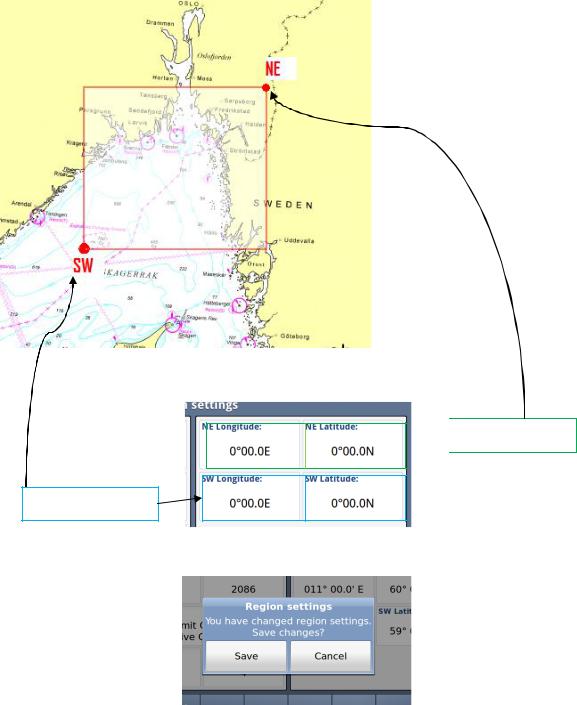
10.1.3.3.5 Define Region
A Region must be between 20 an 200 Nautical miles as described above and you must define the Longitudes and Latitudes of the South West and North East corners:
The values are defined by selecting these 4 buttons:
 North East corner
South West corner
If the values are within 20 – 200 NM, they will be accepted, and you will be asked if you want to save it:
Otherwise you may experience errors:
TR-8000 Operator and Installation Manual |
75 |

10.1.3.3.5.1 Illegal Coordinates
Example: Too large value for Latitude
10.1.3.3.5.2 Region Width /Height problem
Example: Too large value for “Region width”
TR-8000 Operator and Installation Manual |
76 |

10.1.3.4 Alarms
Red square shows 
 button selected to get to next menu
10.1.3.4.1 Alarm Popup
When Alarms occurs, a popup will be shown with status of Alarms:
And the “Alarm” popup must be acknowledged by pressing the button below Alarm window
TR-8000 Operator and Installation Manual |
77 |
The internal Alarm is triggered if a failure is detected in one or more of the AIS functions or data. The corresponding message is given as in Table 2. The most probable source of error and corresponding system behavior is described together with some notes on troubleshooting the error.
|
Alarm |
|
|
description text |
|
Cause / Source of error |
|
Reaction of the system and |
|
|
|
ID |
|
|
|
|
|
|
|
user advise |
|
|
|
|
|
|
|
|
|
|||
|
|
|
|
|
|
|
|
|
||
001 |
|
|
Tx malfunction |
|
VHF Antenna or cabling mismatch. |
|
The Transponder stops transmission. |
|
||
|
|
|
|
|
|
|
Alternatively Invalid MMSI |
|
Check the antenna cabling for short or open |
|
|
|
|
|
|
|
|
|
|
circuits. Alternatively check the VHF |
|
|
|
|
|
|
|
|
|
|
antenna. Check that the MMSI number is |
|
|
|
|
|
|
|
|
|
|
correct. |
|
|
|
|
|
|
|
|
|
|
||
002 |
|
|
Antenna VSWR |
|
VHF antenna or installation |
|
The Transponder continues transmission. |
|
||
|
|
|
|
(Voltage Standing |
|
|
|
Check the VHF antenna and the cabling. |
|
|
|
|
|
|
Wave Ratio) |
|
|
|
|
|
|
|
|
|
|
|
|
|
|
Make sure the cables are 50 Ohm |
|
|
|
|
|
|
exceeds limit |
|
|
|
|
||
|
|
|
|
|
|
|
|
|
||
|
|
|
|
|
|
|
|
|
|
|
003 |
|
|
Rx channel |
1 |
|
Internal frequency error* |
|
The Transponder stops transmission on the |
|
|
|
|
|
|
malfunction |
|
|
|
|
affected channel. |
|
|
|
|
|
|
|
|
|
|
Try rebooting the system |
|
|
|
|
|
|
|
|
|
|
Alternatively, service is needed |
|
|
|
|
|
|
|
|
|
|
|
|
004 |
|
|
Rx channel |
2 |
|
Internal frequency error* |
|
The Transponder stops transmission on the |
|
|
|
|
|
|
malfunction |
|
|
|
|
affected channel. |
|
|
|
|
|
|
|
|
|
|
Try rebooting the system |
|
|
|
|
|
|
|
|
|
|
Alternatively, service is needed. |
|
|
|
|
|
|
|
|
|
|
||
005 |
|
|
Rx channel 70 |
|
Internal frequency error* |
|
The Transponder continues normal |
|
||
|
|
|
|
malfunction |
|
|
|
|
transmission but is not able to receive DSC |
|
|
|
|
|
|
|
|
|
|
messages. |
|
|
|
|
|
|
|
|
|
|
Try rebooting the system |
|
|
|
|
|
|
|
|
|
|
Alternatively, service is needed. |
|
|
|
|
|
|
|
|
|
|
||
006 |
|
|
General failure |
|
Missing MMSI, internal error |
|
The Transponder stops transmission. |
|
||
|
|
|
|
|
|
|
|
|
Check MMSI and the other parameters. |
|
|
|
|
|
|
|
|
|
|
||
007 |
|
|
UTC sync invalid |
|
GPS antenna or installation |
|
The Transponder continues operation using |
|
||
|
|
|
|
|
|
|
|
|
indirect or semaphore synchronisation with |
|
|
|
|
|
|
|
|
|
|
other AIS units. |
|
|
|
|
|
|
|
|
|
|
If the received GPS signal strength is low, |
|
|
|
|
|
|
|
|
|
|
the GPS might use some time to get the |
|
|
|
|
|
|
|
|
|
|
first fix. Consider waiting 15 minutes. |
|
|
|
|
|
|
|
|
|
|
Check the GPS antenna and cabling. |
|
|
|
|
|
|
|
|
|
|
If the antenna is an active type, check that |
|
|
|
|
|
|
|
|
|
|
the phantom DC voltage is correct |
|
|
|
|
|
|
|
|
|
|
|
|
TR-8000 Operator and Installation Manual |
78 |
008 |
MKD connection |
Connection between the Display Unit and |
The Transponder continues operation, and |
|
lost |
the Transponder is corrupted |
alerts other AIS systems that no display is |
|
|
|
present. |
|
|
|
Check that the display is turned on. |
|
|
|
Check that the cable is correct connected in |
|
|
|
both ends. |
|
|
|
Check the IP address and corresponding |
|
|
|
communications IP address of both units if |
|
|
|
using the Ethernet connection. |
|
|
|
Check for firewall error or such if connected |
|
|
|
through a local network. |
|
|
|
|
009 |
Internal / external |
Internal or External GPS or Antennas |
The Transponder continues operation, but |
|
GNSS position |
|
as this might imply that wrong position is |
|
mismatch |
|
used. Care should be taken as this might |
|
|
|
impose a risk both for own and other ships. |
|
|
|
Check the positioning of the GPS antennas. |
|
|
|
Disconnect the External GPS and check if |
|
|
|
the internal GPS provides the correct |
|
|
|
position. |
|
|
|
|
010 |
Navigational |
Setup or speed sensor |
The Transponder continues operation. |
|
Status incorrect |
(Navigational status does not correspond |
Check that navigational status is not at |
|
|
||
|
|
with the given speed) |
anchor, moored or aground while SOG > |
|
|
|
3knots. |
|
|
|
Check that navigational status is not under |
|
|
|
way while SOG = 0 knots. |
|
|
|
Check that SOG is correct. |
|
|
|
|
011 |
Heading sensor |
COG sensor / HDT sensor |
The Transponder continues operation. |
|
offset |
Alarm ID 11 is activated when SOG is |
Alarm indicates mismatch between Course |
|
|
||
|
|
over ground and True heading. Check |
|
|
|
greater than 5 knots and the difference |
|
|
|
sensors. If current speed is <5knots, check |
|
|
|
between COG and HDT is greater than 45 |
|
|
|
SOG |
|
|
|
degrees for 5 min. |
|
|
|
|
|
|
|
|
|
014 |
Active AIS SART |
AIS Search and rescue beacon activated |
The Transponder continues operation. |
|
|
|
Contact local RCC (Rescue Coordination |
|
|
|
Centre). Be prepared to assist in search |
|
|
|
and rescue operation. |
|
|
|
Listen on VHF channel 16 for additional |
|
|
|
information. |
|
|
|
|
025 |
External EPFS lost |
No valid position data on sensor ports |
The Transponder continues operation with |
|
(External Satellite |
|
the internal GPS receiver. If no valid |
|
|
position is present on the internal sensor, |
|
|
Positioning |
|
|
|
|
ALR26 is also displayed. |
|
|
System) |
|
|
|
|
|
|
|
|
|
Check antenna and connections for EPFS, |
|
|
|
check sensor. Check baud rate settings. |
|
|
|
|
026 |
No sensor position |
Internal and external GPS sensor |
The Transponder continues operation. |
|
in use |
|
Check cabling and antenna for the internal |
|
|
|
|
|
|
|
GPS sensor. At start up the GPS might |
|
|
|
need some time to receive almanac data. |
|
|
|
Up to 15 minutes might be required. |
|
|
|
|
029 |
No valid SOG |
Internal and external speed sensor |
The Transponder continues operation using |
|
information |
|
default data. |
|
|
|
Check wiring and external sensor. |
|
|
|
Check baud rate settings. |
|
|
|
|
030 |
No valid COG |
Internal and external course sensor |
The Transponder continues operation using |
|
information |
|
default data. |
|
|
|
Check wiring and external sensor. |
|
|
|
Check baud rate settings. |
|
|
|
|
TR-8000 Operator and Installation Manual |
79 |
032 |
Heading |
External heading sensor |
The Transponder continues operation using |
|
lost/invalid |
|
default data. |
|
|
|
Check wiring and external sensor. |
|
|
|
Check baud rate settings. |
|
|
|
|
035 |
No valid ROT |
External rotation sensor |
The Transponder continues operation using |
|
information |
|
default data. |
|
|
|
Check wiring and external sensor. |
|
|
|
Check baud rate settings. |
|
|
|
|
|
|
|
|
Table 2: Integrity alarm conditions signaled using ALR sentence formatter.
*The Rx Alarm is triggered if one of the internal frequency generators is out of lock, making the receiver unable to function at the correct frequency.
TR-8000 Operator and Installation Manual |
80 |
10.1.3.5 Alarm Relay Output
The Alarm relay is a normally open earth free relay contact, provided as an independent and simple method for triggering an external alarm. The alarm relay is deactivated upon acknowledgment of an alarm, either internally on the display unit, or by an externally provided ACK sentence. If the Transponder power is lost, and the Alarm relay has power, the alarm will be triggered. In this case, the only way to deactivate the Alarm is to power the Transponder unit or disconnect the power source of the Alarm relay.
Figure 10-1 Typical Alarm connection
TR-8000 Operator and Installation Manual |
81 |

10.1.4 Indicators
Red square shows
button selected to get to next menu
The indicators show information about where sensor data are collected, valid Heading etc. This list may be used if troubleshooting of the sensors is needed. The available messages are as given in .
|
“Indicators” |
|
|
(Shown on Display unit and |
Description |
Text |
also sent as text message to |
|
Identifier |
ECS/ECDIS or other equipment |
|
|
connected to PI port) |
|
|
|
|
021 |
External DGNSS in use |
DGNSS is normally the same as DGPS, which indicates external type of |
|
|
such sensor is in use |
|
|
|
022 |
External GNSS in use |
GNSS is normally the same as GPS, which indicates external type of such |
|
|
sensor is in use |
|
|
|
023 |
Internal DGNSS in use (beacon) |
Internal DGNSS (DGPS) (beacon) in use indicates a DGNSS beacon |
|
|
receiver is connected and transmit valid data to TR -8000 |
|
|
|
024 |
Internal DGNSS in use (Message 17) |
Internal DGNSS (DGPS) (Message 17) in use indicates Differential |
|
|
correction data is sent from an AIS Base Station to this TR -8000 |
|
|
transponder |
|
|
|
025 |
Internal GNSS in use |
The inbuilt GNSS (GPS) receiver is in use |
|
|
|
027 |
External SOG/ COG in use |
SOG (Speed Over Ground)/ COG (Course Over Ground) from external |
|
|
GNSS(GPS) device is in use |
|
|
|
028 |
Internal SOG/ COG in use |
SOG (Speed Over Ground)/ COG (Course Over Ground) from internal |
|
|
GNSS(GPS) device is in use |
|
|
|
031 |
Heading valid |
True Heading is received from either an extern al Gyro or Satelitte compass |
|
|
|
033 |
(ROT) Rate of Turn Indicator in use |
ROT received from external sensor: TI (Turn Indicator) |
|
|
|
034 |
Other ROT source in use |
No TI(Turn Indicator) from external sensor, |
|
|
ROT(Rate of Turn) value is calculated from HDT internally |
|
|
|
036 |
Channel management parameters |
If either “Region setting” is applied manually or from msg received |
|
changed |
from AIS Base Station, this indicator will be shown. |
|
|
|
Table 3: Indicators.
TR-8000 Operator and Installation Manual |
82 |

10.2 Advanced Menu
Red square shows
button selected to get to next menu
The Advanced Menu is intended for use during setup and maintenance of the TR-8000 AIS system. Some of the menus are write protected by password, but all parameters are readable to all users for inspection.
10.2.1 Interface
Red square shows
button selected to get to next menu
In the “Interface” menu, the parameters shown on the left picture can be configured.
TR-8000 Operator and Installation Manual |
83 |

10.2.1.1 Display/ Transponder IP
NOTE! Since the TR-8000 uses Ethernet between transponder unit and display, an IP addresses must be correctly configured
All parameters /buttons are “grayed out” as they are not accessible without
“Admin Pswrd”
When “Admin pswrd” button is selected, the following window appear:
Input the “Admin Password” (SE) into the field and press the “Confirm” button: 
Then it is possible to access all fields and configure IP correctly:
Default values are:
Display:
Adress: 10.0.0.11 Mask: 255.255.0.0
Transponder:
Adress: 10.0.0.10 Mask: 255.255.0.0 Gateway: 0.0.0.0
(Gateway is only used if Transponder communicates through a router that performs NAT (Network Address Translation). Then the Router address must be written here as “Gateway”)
And when configuration is finished either of “Return” or “Confirm” |
buttons will bring |
you back to last menu. |
|
TR-8000 Operator and Installation Manual |
84 |
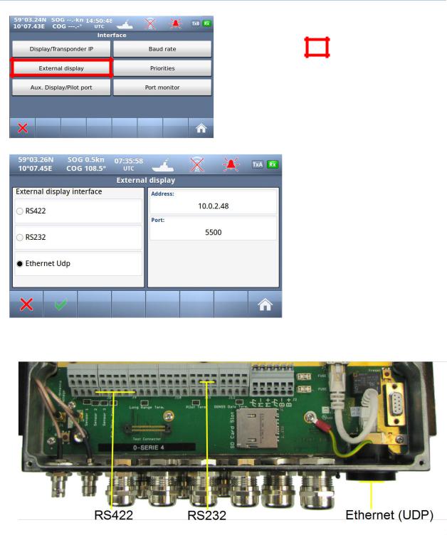
10.2.1.2 External display
Red square shows
button selected to get to next menu
The TR-8000 support three different methods of connecting an external Display.
If Ethernet is used, the External Display should be connected through an external Ethernet switch since the TR-8000 Display unit is already connected to this connector
see also chapter 8.3.1.5 which describes the External Display physical connections
TR-8000 Operator and Installation Manual |
85 |
Loading...