

Page 1

OPERATING MANUAL for
JT - CONTROL SYSTEMS
JT14/... JT26... JT45/... JT70/...
E000
(installation set)
JT-UK
1 of 28
09.10/03/Sie
as from S/N (control board): 1003061
JT
Page 2
OPERATING MANUAL for
JT - CONTROL SYSTEMS
JT14/... JT26... JT45/... JT70/...
E000
(installation set)
JT-UK
2 of 28
09.10/03/Sie
1 ELECTRICAL SAFETY
THE JT CONTROL SYSTEM CARRIES DANGEROUS CURRENT
WHEN IT HAS BEEN CONNECTED TO THE MAINS.
THE JT CONTROL SYSTEM MUST WHEN IN OPERATION BE
EARTHED VIA A GROUND CONDUCTOR WHICH IS
CONNECTED TO THE FRAME TERMINAL PE.
INTERFERENCE VOLTAGE MAY BE PRESENT ALSO IN A
SWITCHED OFF JT CONTROL SYSTEM.
CHECK BY MEASURING WITH A VOLTMETER AT THE MAINS
TERMINALS AND THE RELAY OUTPUT TERMINALS THAT THE
JT CONTROL SYSTEM IS DEENERGIZED BEFORE
COMMENCING WORK.
THE ELECTRICAL INSTALLATION WORK
MUST ONLY BE CARRIED OUT BY AN
AUTHORIZED QUALIFIED CRAFTSMAN.
Warning symbols
For your own safety, please pay particular attention to the
instructions marked with the following symbols:
!
Danger! High voltage
General warning
Page 3

OPERATING MANUAL for
JT - CONTROL SYSTEMS
JT14/... JT26... JT45/... JT70/...
E000
(installation set)
JT-UK
3 of 28
09.10/03/Sie
2 NOTES ON EMC LEGISLATION
The CE mark applied refers to [German] legislation of
09.11.92 governing electromagnetic compatibility (EMC).
Installation of the JT control system must be carried out by
staff trained in EMC.
The JT control system complies with the following
standards or equivalent documents.
1. EN 50081-1
2. EN 50082-2
The JT control system may be used in
− the home, commercial and trade sectors and small
business
− industry
providing that the following measures are observed:
(as shown in the Appendix "Connection Diagram")
• The delivered manufacturer`s mains filter must be used.
• All control cables are screened and connected to the
control equipment at one end.
• The connecting cable between the JT control system
and the vibrator is screened and connected at both
ends.
• The corresponding measures concerning the cabling in
chapter 7.3 must be observed.
Page 4

OPERATING MANUAL for
JT - CONTROL SYSTEMS
JT14/... JT26... JT45/... JT70/...
E000
(installation set)
JT-UK
4 of 28
09.10/03/Sie
3 CONTENTS
1 ELECTRICAL SAFETY ............................................................................ 2
2 NOTES ON EMC LEGISLATION ............................................................. 3
3 CONTENTS .............................................................................................. 4
4 PREFACE ................................................................................................. 5
5 PURPOSE................................................................................................. 6
6 OPERATING PRINCIPLE ........................................................................ 6
7 INSTALLATION........................................................................................ 7
7.1 CONSTRUCTION .................................................................................. 7
7.2 NOTES ON INSTALLATION.................................................................. 7
7.3 WIRING.................................................................................................. 8
7.4 CONNECTIONS..................................................................................... 9
7.5 SPECIAL CHARACTERISTICS............................................................. 9
7.5.1 Regulator release................................................................................ 9
7.5.2 Output-side switching.......................................................................... 9
7.5.3 Actual value failure protection........................................................... 10
7.5.4 Switching on the setpoint signal........................................................ 10
7.5.5 Applications for coarse/fine feed setpoint ......................................... 10
7.5.6 Manual/automatic applications.......................................................... 10
7.5.7 Multiple drive applications................................................................. 10
8 COMMISSIONING .................................................................................. 11
8.1 CHECKS BEFORE SWITCHING ON THE MAINS VOLTAGE ........... 11
8.2 SWITCHING ON THE MAINS VOLTAGE ........................................... 11
8.3 SETPOINT INTEGRATOR .................................................................. 12
8.4 ACTUAL VALUE OUTPUT .................................................................. 12
8.5 OUTPUT RELAY.................................................................................. 13
9 SETTINGS / RECONFUGURATION...................................................... 14
AND
9.1 POSITION OF ADJ. ELEMENTS
9.2 EXPLANATION OF ADJUSTMENT ELEMENTS ................................ 14
9.3 MATCHING THE SETPOINT SOURCE .............................................. 15
9.4 FIXING THE CONTROL MODE .......................................................... 16
9.5 CHOOSING THE OUTPUT FREQUENCY.......................................... 16
9.6 MATCHING THE MAINS VOLTAGE ................................................... 17
9.7 CONTROL SYSTEM CALIBRATION................................................... 17
9.8 PI-REGULATOR .................................................................................. 17
9.9 STROKE SENSOR CONNECTION..................................................... 18
10 MAINTENANCE.................................................................................... 18
11 FAULT FINDING................................................................................... 18
12 ADDITIONAL EQUIPMENT ................................................................. 20
13 APPENDIX............................................................................................ 21
COMPONENTS....................... 14
13.1 TECHNICAL DATA ............................................................................ 21
13.2 TYPE KEY.......................................................................................... 23
13.3 SCOPE OF SUPPLY ......................................................................... 24
13.4 FUSES ............................................................................................... 24
13.5 DIMENSIONS .................................................................................... 25
13.6 CONNECTION DIAGRAM................................................................. 27
Page 5

OPERATING MANUAL for
JT - CONTROL SYSTEMS
JT14/... JT26... JT45/... JT70/...
E000
(installation set)
JT-UK
5 of 28
09.10/03/Sie
4 PREFACE
The information contained in this manual refers exclusively to JT
control systems.
It is essential that you read this manual before installation and
commissioning.
The limits specified in the technical data must be observed when using
the control system.
The guarantee for manufacturers' drives and equipment does not
cover defects caused by misuse or incorrect use of these control
systems.
The manual is divided into individual sections in accordance with the
table of contents.
Section 1 "Electrical safety" and Section 2 " Notes on EMC legislation"
must be read before working with the JT control system.
It is essential that the user familiarises himself with this manual before
using the drive/equipment or before carrying out adjustment work
specific to the operations.
Please contact the manufacturer directly if you have any questions
about the JT control system.
The manufacturer reserves the right to make product changes without
prior notice.
Page 6

OPERATING MANUAL for
JT - CONTROL SYSTEMS
JT14/... JT26... JT45/... JT70/...
E000
(installation set)
JT-UK
6 of 28
09.10/03/Sie
5 PURPOSE
The JT Control Systems are intended for the operation of vibrating
systems with manufacturers` electromagnetic drives from an a.c.
mains.
With the JT Control System the stroke (vibration amplitude) of such
an installation can be adjusted from almost 0 to maximum.
In the control mode 'K' (= voltage regulation), fluctuations in the
supply voltage of ±10% have nearly no effect on the stroke.
In the control mode 'Y' (= stroke regulation), fluctuations of ±10%, as
well as a change in the mass conditions, e.g. through bunker
pressure, have no effect on the stroke.
6 OPERATING PRINCIPLE
With the potentiometer supplied or an external mA- or voltage signal
as the setpoint source, the stroke and therefore the feed rate of an
electromagnetic vibratory system can be continuously adjusted
within certain limits (minimum or maximum value resp.).
The setpoint signal is compared with the actual value signal. (The
actual value signal is, with the control mode 'K', the output voltage of
the control system to the drive and, with the control mode 'Y', the
signal of the stroke sensor on the vibratory system). The differential
signal (regulation deviation) is passed to a PI-action controller, which
generates the setting signal for the phase control system. The
setting signal determines the firing point of the thyristor-module.
The firing pulses are passed to the thyristor-module for galvanic
separation via a firing transformer. Firing takes place only within the
positive sinusoidal half-wave. The negative is suppressed by the
thyristor. The phase control within the positive sinusoidal half-wave
controls the electrical output of voltage and current, which is passed
to the vibratory system.
Page 7
OPERATING MANUAL for
JT - CONTROL SYSTEMS
JT14/... JT26... JT45/... JT70/...
E000
(installation set)
JT-UK
7 of 28
09.10/03/Sie
7 INSTALLATION
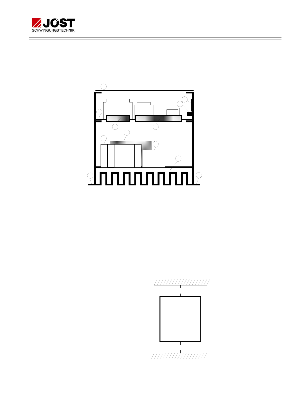
7.1 CONSTRUCTION
The major components of the JT control system are as follows:
1
5
10
2
3
6
7
12 34
9
1. Perspex cover
2. Control board
3. Connection plug X3 between control board and power
section
4. Control terminals X2
5. Rating plate
6. Thyristor-module with RC snubber network
7. Mains connection/drive/earth terminal X1
8. Heatsink
9. Fixing holes
10. Assembling bolt for screening
7.2 NOTES ON INSTALLATION
Cooling
:
4
4
17182627PE PE
8
9
The JT control system is
cooled by natural
convection. In order to
guarantee an adequate
air flow, the equipment
must be mounted upright
and the minimum
distances shown in the
adjacent illustration
observed. The cooling
air must be as clean as
possible and free of
aggressive substances.
Should the cooling air
contain dust, the cooled
areas must be cleaned regularly.
a
JT-
Control
System
60 mm
JT 14 to JT26:
a = 60 mm
JT45 to JT70:
a = 80 mm
Page 8
OPERATING MANUAL for
JT - CONTROL SYSTEMS
JT14/... JT26... JT45/... JT70/...
E000
(installation set)
JT-UK
8 of 28
09.10/03/Sie
Mounting:
Fixing dimensions, also for the mains filter, are to be found in the
appendix.
The JT Control system is fixed on the assembly board with four
screws inserted through slots.
Fit four fixing screws, hook on the control unit and tighten the four
screws.
The control system should be placed in a shock- and vibration-free
position.
7.3 WIRING
Mains and drive cable sizes:
Values are based on a cable length of 50 m between the control
system and drive. The cable diameters must be increased
appropriately for longer distances.
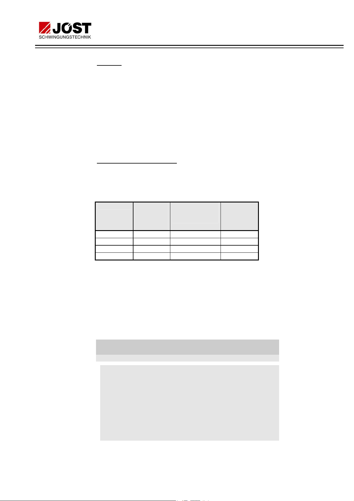
Allocation table: Control system / back-up fuse / cable / mains filter
JT-type 2-pole
back-up
fuse
[A, retarded]
Mains and drive
cable crosssection
1)
1) 2)
[mm²]
matching
mains filter
3)
Type
JT 14/... max.16 2.5 2x16
JT 26/... max. 35 6.0 2x35
JT 45/... max. 50 10.0 2x50
JT 70/... max. 80 25.0 2x80
1)
adapted to IN of the drive.
2)
The local regulations governing earthing and cables must be
observed.
3)
To be used within the scope of the EC directive 89/336/EEC
concerning EMC.
As the connecting cable between electromagnetic drive and
stationary terminal box we recommend the use of a flexible cable of
the type H07RN-F resp. NSSHöU-J. For the use of screened cables
we recommend the type ÖLFLEX 540 CP.
Additional measures within the scope of the EMC
directive 89/336/EEC:
(also refer to connection diagram in the appendix)
Mains supply: For this case, the delivered mains filter must be
switched into the mains supply line of the JT
control system. The filter must be directly mounted
on the left hand side next to the JT control system.
Sufficient ground contact must be observed. The
connection between the filter (wiring side named
„LOAD“) and the JT control system must be as
short as possible. For the filter types upto 2x35 the
filter-own output wires must be used. As from the
filter type 2x50 the connection must be made by
single wires of max. 20 cm length.
Page 9

OPERATING MANUAL for
JT - CONTROL SYSTEMS
JT14/... JT26... JT45/... JT70/...
E000
(installation set)
JT-UK
9 of 28
09.10/03/Sie
For the mains supply all filters are fitted with
clamps on the „LINE“ side. The connection of the
ground conductor is built as threaded bolt as from
filter type 2x50.
Drive connection:A screened cable between JT control system
and drive must be used. The screen connection
must be as short as possible and connected to
ground on both ends.
Control cable:
The control cable must be screened
multicore flexible cable with a conductor cross-section of 0.5 or 0.75
mm² for the control system connection.
N:B.: Earth the cable screen - as short as possible - at the JT control
system end. Use the assembling bolt (see 7.1 „Construction“,
Pos.10).
The control cables must be positioned at least 0.5 m from the drive
cable, to prevent interference.
7.4 CONNECTIONS
Please refer to the connection diagram in the appendix or the
connection sheet enclosed with the control system for the assignment
of terminals for the mains, drive and control system cables.
N.B.: If the setpoint potentiometer is used, please ensure that the
correct connection sequence is observed.
7.5 SPECIAL CHARACTERISTICS
7.5.1 Regulator release
The control system is fitted with an input for the regulator release
(control system terminals X2.14/15).
The regulator is blocked when the terminals are open. The drive will
be idle.
The regulator is released when the terminals are shorted. The drive
will vibrate.
. We recommend a screened,
When the drive is switched off by the regulator release,
connection terminals X1.3/4 will not be disconnected
from the mains.
If the operating process requires the drive to be switched on and off
frequently, the "regulator release" must be used instead of switching at
the mains. The control system therefore remains connected to the
mains current.
7.5.2 Output-side switching
It is only permissible to switch the output if the control system is
switched off (at the mains end or via the regulator release). Switches
or contactors with appropriate maximum loads must be used for this.
Page 10

OPERATING MANUAL for
JT - CONTROL SYSTEMS
JT14/... JT26... JT45/... JT70/...
E000
(installation set)
JT-UK
10 of 28
09.10/03/Sie
When switching between the control system and the drive, the "V"
protective unit
remain on the drive when the control system is switched off.
7.5.3 Actual value failure protection
The control system is provided with a built-in actual value failure
protection facility. If the actual value fails, e.g. through cable fracture
on the stroke sensor, the drive is operated with a constant voltage
which is reduced as vis-a-vis the maximum output voltage. The
stroke can then no longer be influenced via the setpoint. Only after
the fault has been corrected is normal operation possible again.
7.5.4 Switching on the setpoint signal
If switching is to be carried out in the setpoint cables, relays with gold
contacts or hermetically sealed relays must be used, because of the
low switching voltage (U ≤ 10V=, I ≤ 20 mA). Please note that, with
mA signals, the load resistor is located on the control board.
(see section on "Additional Equipment")
must be used. It must
7.5.5 Applications for coarse/fine feed setpoint
A setpoint pre-setting is possible for coarse and fine feed in metering
and weighing applications. If the setpoint is preset by potentiometers,
a second potentiometer is required (to be ordered separately). The
setpoint for coarse feed will then be preset from the first potentiometer,
and for the fine feed from the second. An example of wiring can be
found in the appendix "Connection diagram". Terminals 26/27 only
function as post terminals for the slider, i.e. they are not used for the
control system.
An external setpoint signal (mA or V) can also be used for the
aforementioned applications. A signal of 2 Volts would then be the fine
feed value, and 8 volts the coarse feed value for example.
7.5.6 Manual/automatic applications
Manual/automatic applications means that the actual setpoint (=
automatic) comes from an external source (regulator / PLC as mA or
V). A setpoint from a manual potentiometer can be provided by
switching instead of the automatic setpoint of the control system (->
manual). An example of wiring can be found in the appendix
"Connection diagram".
The selector switch S2 (setpoint source) must then be set to the
automatic setpoint signal.
7.5.7 Multiple drive applications
Should more than one drive be connected to a control system, it is
necessary to connect the single drives through separating diodes (
section on "Additional equipment")
. Please consult the manufacturer.
see
Page 11

OPERATING MANUAL for
JT - CONTROL SYSTEMS
JT14/... JT26... JT45/... JT70/...
E000
(installation set)
JT-UK
11 of 28
09.10/03/Sie
8 COMMISSIONING
8.1 CHECKS BEFORE SWITCHING ON THE MAINS VOLTAGE
The JT control system is pre-set ex works to the vibrating plant
supplied, and can thus be used without any further adjustments.
Exception: A tag on the control system makes reference to further
adjustment.
The adjustment trimmers P1-P4 and the selector
!
Should settings be required other than those supplied, please read the
section "Settings/Reconfiguration".
Check the following points before switching on the mains voltage:
switches SW 1 and SW2 on the JT control board may
not be altered.
1. The control system must be connected to the appropriate
vibrating plant
2. The information on the rating plate on the control system must
match the details of the drive. It is especially important that the
output frequency of the control system matches the vibration
frequency of the drive.
3. The nominal mains voltage must lie within the voltage range
specified on the rating plate (entry under "V" on the rating plate).
4. The fuse holder with super-quick acting fuse supplied must be
inserted in the mains cable to the terminal X1.1.
5. The fuse must have the ampere value matching the control
system (see type designation on the rating plate and
allocation table in the Section 'Fuses' in the appendix).
6. The control system must be earthed via the PE terminal.
7. The measures to observe EMC legislation must be implemented
(see section 2).
8. The mains cable must be connected to the appropriate terminals
9. The drive cable must be connected to the appropriate terminals
10. The appropriate setpoint source must be connected (see type
designation on the rating plate and explanation of the type key in
the appendix).
11. Set the setpoint source to minimum (0/4 mA, 0V, or setpoint
potentiometer to 0).
12. Terminals 14/15 must be bridged if no external regulator
release is connected.
Only applicable if an external regulator release is connected: A
break contact must be connected to terminals 14/15 and the
bridge used must be removed
Only for control units of Type JT../..E..K.. : (voltage reguation)
13.The control terminals X2.17/18 must be bridged.
Only for control units of Type JT../..E..Y.. : (stroke regulation)
13.The control terminals X2.17/18 must not
14.The stroke sensor supplied with the equipment must be
mounted on the vibratory machine and correctly connected to
the control system.
8.2 SWITCHING ON THE MAINS VOLTAGE
The points listed under 8.1 must be checked before the mains voltage
is switched on.
be bridged.
Page 12

OPERATING MANUAL for
JT - CONTROL SYSTEMS
JT14/... JT26... JT45/... JT70/...
E000
(installation set)
JT-UK
12 of 28
09.10/03/Sie
The mains voltage can now be switched on.
A dangerously high voltage will now be present in the JT
control system.
The green light emitting diode LED1 „Voltage on“ must now light.
The red light emitting diode LED2 „Regulator release“ must be off.
N.B.: If LED2 is on, the regulator release must be obtained by
closing the contact at terminals X2.14/15
The make contact of output relay at terminals X2.12/13 is closed.
The vibrating plant must now work at minimum vibration amplitude.
The setpoint signal can now be slowly set to maximum. The vibration
plant must operate at the maximum setpoint with the vibration
amplitude, as specified in the technical documentation for the
equipment.
When the setpoint signal is increased, consideration
!
If there is no fault in operation, the operating setpoint may be adjusted
and the material to be conveyed supplied.
Should further adjustment of the control system be required due to
customer's circumstances, please read the section "Settings /
Reconfiguration".
must be given to the operating noise level of the vibrating
plant. If contact noises can be heard, the vibrating plant
must be stopped immediately. The plant can be switched
on again after the cause of the problem has been
rectified.
8.3 SETPOINT INTEGRATOR
In applications where the vibratory machine is to reach the preset
stroke slowly, there is the possibility of delaying the setpoint signal
by means of a soft start stage.
The acceleration period can be infinitely preset between 0 and 15
seconds with the trimming potentiometer P5 on the control board.
Trimming potentiometer P5 at the left-hand stop corresponds to
approx. 0 seconds. Trimming potentiometer P5 turned clockwise up
to the right-hand stop corresponds to 15 seconds.
N.B.: P5 can be actuated with a narrow screwdriver through
the opening in the perspex cover. Please consult the
position diagram to find the location of P5 (see 9.1).
8.4 ACTUAL VALUE OUTPUT
The control system is equipped with an actual value output 0 - 10 V=
as standard. It can be used for connecting display/monitoring
units.This output has not been calibrated in the works. Calibrating is
done with the trimming potentiometer P6 on the control board. If the
actual value output is used, the output must be calibrated at
maximum setpoint value. To do this, connect a voltmeter
(measurement range 20 V=, Ri > 10 KΩ) to the control terminals
X2.11 (+) and X2.7 (0V). Set 10 V= on the voltmeter with P6 by
turning anticlockwise. After that the corresponding
display/monitoring unit can be connected.
NOTE: P6 can be actuated with a narrow screwdriver
through the opening in the perspex cover. Please consult
the position diagram for the location of P6 (see 9.1).
Page 13

OPERATING MANUAL for
JT - CONTROL SYSTEMS
JT14/... JT26... JT45/... JT70/...
E000
(installation set)
JT-UK
13 of 28
09.10/03/Sie
When applying the stroke control unit 'J', refer to the
corresponding manual, to set the actual value output.
8.5 OUTPUT RELAY
A voltageless make contact of the output relay is available at the
control terminals X2.12/13.
Contact closed: Mains voltage on and regulator release provided,
i.e. control sytem in operation.
Contact open: Mains voltage off and/or regulator release not
provided.
Contact rating: see 'Technical data'
Page 14

OPERATING MANUAL for
JT - CONTROL SYSTEMS
JT14/... JT26... JT45/... JT70/...
E000
(installation set)
JT-UK
14 of 28
09.10/03/Sie
9 SETTINGS / RECONFUGURATION
9.1 POSITION OF ADJ. ELEMENTS and COMPONENTS
X6
GND
P1 P2 P3 P4 P5
LED1
P6
Mains transformer
SW1
1234
SW2
12345
Si1
400V
500V
GE
230V
R42
50mAT
X3
LED1: Light emitting diode (green) for „Voltage on“
LED2: Light emitting diode (red) for „Regulator release“
X4
Diagnosisplug
-
+
C4
LED2
Relay
X2
X2
9.2 EXPLANATION OF ADJUSTMENT ELEMENTS
IMPORTANT NOTE:
!
Unauthorised resetting of the adjustment elements can
cause malfunctions in the control system.
It is essential to read the following before changing the
settings.
Trimming potentiometer:
There are six trimming potentiometers on the control board.
Function of the trimming potentiometers:
P1: Limitation of the maximum output voltage *)
P2: Adjustment of the minimum output voltage
P3: Matching the actual value signal
P4: Setting the rated stroke
P5: Adjustment of the soft start time
P6: Calibration of the actual value output
*) P1 has been sealed in the works and must not
Selector switch (DIP switch):
be adjusted!
A four-way (SW1) and a 5-way (SW2) selector switch (DIP switches)
is arranged on the control board.
The individual switches are sliding switches. These are numbered 14 and 1-5 from left to right respectively.
Page 15

OPERATING MANUAL for
JT - CONTROL SYSTEMS
JT14/... JT26... JT45/... JT70/...
E000
(installation set)
JT-UK
15 of 28
09.10/03/Sie
Operation of the sliding switches is permissible only
!
when the power (mains) is turned off. The perspex cover
of the control system must be removed for adjustment.
SW 1 *)
ON
1234
Function of the selector switches in the ON
position (slide switch pushed upwards):
Control mode 'K' (voltage regulation)
Control mode 'Y' (stroke regulation)
*) SW 1 has been sealed in the works and must not
Function of the selector
switches in the ON position
(slide switch pushed upwards):
Output frequency 25/30 Hz
ON
SW 2
123 45
1
Actual value attentuation
Setpoint with „life zero“ (4 mA)
Setpoint as voltage signal or via
setpoint potentiometer
Setpoint as mA-signal
be adjusted !
9.3 MATCHING THE SETPOINT SOURCE
The control system is matched to the various setpoint sources with
selector switch SW2 (1-3).
Operation of the sliding switches is permissible only
!
To gain access to the slide switches, the cap of SW 2 must be
raised on the right-hand side with a small screwdriver. On
completion of the work, close the cap again and screw the perspex
cover on tight.
N.B.: Changing the setting of SW2 (1-3) does not
when the power (mains) is turned off. The perspex cover
of the control system must be removed for adjustment.
resetting the trimmers P1-P6.
necessitate
Page 16

OPERATING MANUAL for
JT - CONTROL SYSTEMS
JT14/... JT26... JT45/... JT70/...
Setting switches SW 2 (1-3):
SW 2
ON
12345
SW 2
ON
12345
SW 2
ON
12345
E000
(installation set)
Setpoint value 0-10V at terminal X2.7/8
and/or setpoint potentiometer at X2.5/7
Setpoint 0-20 mA at terminal X2.7/8
Setpoint 4-20 mA at terminal X2.7/8
JT-UK
16 of 28
09.10/03/Sie
9.4 FIXING THE CONTROL MODE
The control mode is determined with selector switch SW 1.
Operation of the sliding switches is permissible only when
!
switches, the cap of SW 1 must be raised on the right-hand side with
a small screwdriver. On completion of the work, close the cap again
and screw the perspex cover on tight.
ON
ON
N.B.: The switches of SW 1 must always be switched in pairs.
the power (mains) is turned off. The perspex cover of the
control system must be removed for adjustment.
To gain access to the slide
SW 1
1234
SW 1
1234
Changing the control mode requires a readjustment
the trimmers P1-P6. This may only be carried out by the
manufacturer's service department.
Control mode 'K' (voltage regulation)
Control mode 'Y' (stroke regulation)
of
9.5 CHOOSING THE OUTPUT FREQUENCY
The output frequency of the control system is determined with SW 2
(5).
Operation of the sliding switches is permissible only
!
To gain access to the slide switch, the cap of SW 2 must be raised
on the right-hand side with a small screwdriver. On completion of the
work, close the cap again and screw the perspex cover on tight.
when the power (mains) is turned off. The perspex cover
of the control system must be removed for adjustment.
Page 17

9.6 MATCHING THE MAINS VOLTAGE
OPERATING MANUAL for
JT - CONTROL SYSTEMS
JT14/... JT26... JT45/... JT70/...
SW 2
ON
12345
SW 2
ON
12345
N.B.: Changing the output frequency requires a readjustment
of the trimmers P1-P6. This may only be carried out by
the manufacturer's service department.
There is a selector plug on the control board for selecting the mains
voltage.
E000
(installation set)
Output frequency 50 or 60 Hz resp.
Output frequency 25 or 30 Hz resp.
JT-UK
17 of 28
09.10/03/Sie
Selector plug carries mains voltage.
Control system
the selector plug is re-plugged. Check for isolation from
N.B.: Changing the mains voltage requires a readjustment
9.7 CONTROL SYSTEM CALIBRATION
The control system should be calibrated by the manufacturer's
service department.
Slight stroke over- or undershooting in the upper max. vibration
range can be readjusted with the trimming potentiometer P4.
the supply! The perspex cover of the control system
must be removed.
the trimmers P1-P6. This may only be carried out by the
manufacturer's service department.
Mains voltage
between
200 - 250 V
380 - 440 V
460 - 525 V
must be isolated from the mains before
Selector plug
position
GE
- 230
GE
- 400
GE
- 500
Pull selector plug with
insulated pointed pliers
and plug into new
position.
of
9.8 PI-REGULATOR
Due to the capacitor C4 (see 9.1) the control characteristic is affected. Increasing
the capacitor value will result in a higher dampening of the regulation. The
standard value is 2.2µF / 16V for voltage regulation. For stroke regulation in
conjunction with sensor JSEN1 C4 will be increased to 4.4µF (2x 2.2µF in
parallel). This is marked on the rating plate with the addition „-005“.
C4 is an electrolyte-capacitor. Pay particular attention to the exact polarity when
soldering in.
Page 18

OPERATING MANUAL for
JT - CONTROL SYSTEMS
JT14/... JT26... JT45/... JT70/...
E000
(installation set)
JT-UK
18 of 28
09.10/03/Sie
9.9 STROKE SENSOR CONNECTION
For stroke regulation the sensor JSEN1 must be connected to the control system
as an actual value source. The sensor output signal, between 0 mA and max.
20mA, is proportional to the stroke. Within the JT control system this mA-signal is
converted into a voltage signal by using resistor R42 [390
When combining the JT control system with the sensor type G5/Y resp. G6/Y
(almost in existing installations), the resistor R42 must be removed using a side
cutting pliers.
10 MAINTENANCE
The JT control system is largely maintenance-free.
However, under very dusty conditions, regular cleaning is essential.
The operating current of the drive should be measured during each
maintenance inspection with a TRMS ammeter. In addition, the
maximum vibration amplitude of the vibrating plant must be checked
(see the documentation on the drive for the nominal values)
Ω] (see 9.1).
11 FAULT FINDING
Please make a note of the following details before reporting a defect to
our service department:
− type of the control system (see rating plate)
− control system number (see rating plate)
− Serial number of the power stage (on the heatsink)
− Serial number of the control board (on the underside of the control
board)
− mains voltage (measured)
− drive data
− defects established
Page 19

OPERATING MANUAL for
JT - CONTROL SYSTEMS
JT14/... JT26... JT45/... JT70/...
E000
(installation set)
JT-UK
19 of 28
09.10/03/Sie
This page has been deliberately left blank
Page 20

OPERATING MANUAL for
JT - CONTROL SYSTEMS
JT14/... JT26... JT45/... JT70/...
E000
(installation set)
JT-UK
20 of 28
09.10/03/Sie
12 ADDITIONAL EQUIPMENT
The following additional equipment is available for the JT control system:
− Stroke control unit "J"
Limit value switch to monitor the stroke within MIN/MAX limit value
contacts.
− Fault signalling unit "H"
Current relay to monitor the drive current. If the minimum level is not
reached, e.g. due to a cable breakage, a fault signalling contact is closed.
− Motor potentiometer "P"
This unit is required for remote adjustment of the setpoint value via „+/-“
switches and for the setpoint potentiometer for larger cable distances.
− Setpoint voltage source "Q"
Provides a constant voltage of 10 V= for the setpoint potentiometers.
− Protective unit "V"
Required for protection of the drive, when switching between the control
system and the drive takes place.
− Separating diodes "F"
When more than one drive is connected to a control system, it may be
necessary to install this component to prevent mutual electrical
interference.
− Protective device "N"
Necessary to limit the current in drives protected for use in hazardous
(Ex.) locations. Must be connected between the control system and said
drive.
Page 21

OPERATING MANUAL for
JT - CONTROL SYSTEMS
JT14/... JT26... JT45/... JT70/...
E000
(installation set)
JT-UK
21 of 28
09.10/03/Sie
13 APPENDIX
13.1 TECHNICAL DATA
POWER STAGE
Nominal mains voltage 230 V, 400 V, 500 V,
(2Ph/1Ph+N), switchable
Mains voltage ranges 200 - 250 V
380 - 440 V
460 - 525 V
Perm. voltage fluctuations + 5 %, (based on mains voltage
range max.)
- 10 %, (based on mains
voltage range min.)
Nominal mains frequency 50/60 Hz; ± 1 %
max. output current 14 / 26 / 45 / 70 A
Output frequency 50 or 25 Hz
60 or 30 Hz
Max. power dissipation Pv (W)
JT 14 26 45 70
Pv 21 39 68 105
CONTROL AND REGULATION SECTION
Supply voltage as mains voltage
Internal voltages ± 15V stabilized, short-circuit
Setpoint input 0/4 - 20 mA, int. load 250
Setpoint integrator adjustable (0 - 15 sec)
Actual value input adjustable sensitivity;
Regulator PI-characteristics
Setpoint linearisation activated at voltage regulation
Actual value output 0 - 10 V, RL
proof
+10V stabilized, short circuit
proof, for max. 4 setpoint
potentiometers (5 K
0 - 10 V; 0/1 - 5 V;
selectable by DIP-switch
failure protection;
with stroke regulation:
0 - 10 V AC/DC;
internal load when combined
with sensor JSEN1: 390
with voltage regulation:
0 - U
mode
mains
(V)
≥ 10 KΩ
Ω)
Ω;
Ω;
Page 22

OPERATING MANUAL for
JT - CONTROL SYSTEMS
JT14/... JT26... JT45/... JT70/...
E000
(installation set)
JT-UK
22 of 28
09.10/03/Sie
Indicating light 2 x LED; one for ´voltage on´,
the other one for ´regulator
release´
Regulator release via external potentialfree break
contact;
closed-circuit principle
Operating indication relay make contact,
switching capacity:
1A/250VAC/30VDC.
Ext. contactors must be
provided with RC- or VDR
protective circuits resp. freerunning diodes
OTHER DATA
Tests EN 50081-1
Type of cooling air self-cooling
Max. installtion altitude 1000 m (if over 1000m: please
Perm. moisture stress DIN 40040 F
Degree of protection (DIN 40050) IP 00
Operating temperature 0°C to + 45°C
Storage and transport temp. - 10°C to + 85°C
Installation position vertical
Perm. constant vibration level
Weight 3.5 kg
Dimensions 190 x 160 mm (WxH) base
MAINS FILTER
Filter
Type
2x16 500 16 2,5 4,0 / cable 2,0
2x35 500 35 2,5 4,0 /cable 2,0
2x50 500 50 2,5 25 / terminal 3,5
2x80 500 80 5,1 25 / terminal 3,5
nominal
volt. [V]
nominal
current [A]
EN 50082-2
consult manufacturer)
≤ 0.5 G
surface
167 mm deep
leakage
current [mA]
Connection at
„LOAD“ [mm²]
Weight
[kg]
Page 23

OPERATING MANUAL for
JT - CONTROL SYSTEMS
JT14/... JT26... JT45/... JT70/...
E000
(installation set)
JT-UK
23 of 28
09.10/03/Sie
13.2 TYPE KEY
The designation of the JT control system on the rating plate is made
up as follows:
JT 14 / 400 Exxx - 50 K 10 - yyy
special design
000 - 999
Additional connection
0 = no separating diodes
1 = separating diodes
Setpoint signal
1 = potentiometer
2 = 0 - 10 V
3 = 0 - 20 mA
4 = 4 - 20 mA
5 = special signal
6 = universal, 1 and 2 preset
Control mode
K = voltage regulation
Y = stroke regulation
Output frequency (Hz)
50, 60, 25, 30,
Exxx = installation set
(always E000)
Gxxx = casing
xxx = 000 to 999
e.g. G000 = standard execution
G001 = with coarse/fine feed
G002 = Manu/Auto setpoint
Nominal mains voltage (V)
e.g.: 400
max. output current (A)
14 / 26 / 45 / 70
Control system type
Page 24

OPERATING MANUAL for
JT - CONTROL SYSTEMS
JT14/... JT26... JT45/... JT70/...
E000
(installation set)
JT-UK
24 of 28
09.10/03/Sie
13.3 SCOPE OF SUPPLY
The following are supplied with the JT control system:
1 setpoint value potentiometer with scale and rotary knob
1 connection diagram
1 fuse (super-quick acting)
1 fuse holder
Additional supply within the validity of the EMC-Directive:
1 Mains filter (JT-filter) /
Additionally required for control system type JT../..E000-..
regulation):
1 stroke sensor JSEN1 (
13.4 FUSES
Allocation table: Fuse holder / control system:
Control
system type
JT 14/... 16 14x51 Type1 DIN-rail
JT 26/... 32 14x51 Type1 DIN-rail
JT 45/... 63 22x57 Type2 DIN-rail
JT 70/... 80 R 1/
!
N.B.: The fuse and fuse holder contained in the scope of supply
must be connected to the mains cable at terminal X1.1.
The super-quick acting fuse protects the thyristor in the
event of a short-circuit. Only the same type may be used
when the fuse is replaced.
Fuses for cable and drive protection are not our scope of
supply. Dimensioning acc. to nominal current of drive.
Fuse
[A FF]
With long periods of operation the temperature of the
fuse may exceed 100°C. Before replacing the fuse
allow it to cool for about 15 minutes.
Switch off the mains voltage before replacing the fuse.
(as far as not otherwise ordered)
resp. G5/Y or G6/Y
Fuse
[mm]
)
Fuse
holder
1/4
Type3 Screws
Attachment
Y.. (stroke
Page 25

OPERATING MANUAL for
JT - CONTROL SYSTEMS
JT14/... JT26... JT45/... JT70/...
E000
(installation set)
JT-UK
25 of 28
09.10/03/Sie
13.5 DIMENSIONS
JT control system / Mains filter:
(Mains filter only within the scope of EC directive 89/336/EEC for
EMC)
160
150
50
38
LINE
Mains
filter
2x16
2x35
Depth: 121
Mounting:
by screws M5
5,5
LOAD
100
60
4,2
8,5
190
176
JT control sytem
JT14 to JT26
Depth: 167
Mounting: by screws M4
Clearance: above: 60 mm
Connection terminals
below: 80mm
106
160
Mains
filter
175190240
2x50
2x80
6,5
all dimensions in mm
LINE
Depth: 90
Mounting:
by screws M6
LOAD
4,2
8,5
190
176
JT control system
JT45 to JT70
Depth: 167
Mounting: by screws M4
Clearance: above:
Connection terminals
below:
80mm
80mm
106 160
Page 26

OPERATING MANUAL for
JT - CONTROL SYSTEMS
JT14/... JT26... JT45/... JT70/...
E000
(installation set)
JT-UK
26 of 28
09.10/03/Sie
Fuse holder types 1 to 3:
26 34,8 67
106
Type1
Type2
140
118
Type3
O7
44
For JT14 / JT26 For JT70
Mounting:
DIN rail
Height incl.
swivell lever:
98mm
All dimensions in mm
For JT45
Mounting:
DIN rail
Height incl.
swivell lever:
112mm
Height incl.
screw cap:
95mm
5 K
Ω potentiometer with scale and rotary knob:
O 28mm
Scale : 64 x 64 mm
a
b
M10
O 6mm
Centre hole :
c
16
88
Rotaty knob :
Height :20 mm
44
∅ 11 mm
∅ 36 mm
Page 27

OPERATING MANUAL for
JT - CONTROL SYSTEMS
JT14/... JT26... JT45/... JT70/...
E000
(installation set)
JT-UK
27 of 28
09.10/03/Sie
13.6 CONNECTION DIAGRAM
F
K
F1
4
*)
X1.
X1. X2.
43PE
*)
Vibrator
Mains
b
PE
12
Line
JT-FILTER
Load
sw br gn/ge
PE
JT../...E000
17 18 9 10
Terminals 17+18
PE
carry
dangerous
voltage
Output
Actual value output
0 - 10 V=
Ri > 10 k
V
X2.12PE
50mAT
0V
1
2
70V11 12 13
+24V
14 15 6+570V82627
a
Regulator release
Open: STOP
Close: START
Input
3
In operation
250VAC/30VDC
max. 1A
Setpoint
(See next page)
*)
Required measures according to EC-directive 89/336/EEC for EMC
N.B.:
1
Remove link 17-18 only if:
2
Stroke sensor connection only with JT../...E000-..Y.. : see next page
3
External contactors must be fitted with RC- or VDR protective circuits resp. free running diodes
Fuse F1 (super-quick-acting), fuse holder
4
and JT-FILTER will be partially delivered
Terminal X2.15 (24V) is only to be used for connecting the regulator release contact and the sensor JSEN1
a
Back-up fuse F: by customer; adapted to nominal current of drive
b
a) combined with separating diodes tpye "F"
b) stroke sensor JSEN1 resp. G5/Y or G6/Y is connected
Page 28

OPERATING MANUAL for
JT - CONTROL SYSTEMS
JT14/... JT26... JT45/... JT70/...
E000
(installation set)
JT-UK
28 of 28
09.10/03/Sie
Setpoint connection
Potentiometer
+0V
6578
X2
c
R1
b
5 k
a
External signal Manual-Auto mode
+0V
6578
X2
N.B.:
5
POTI R1:
6
POTI R2: order separately
Partially delivered with scale and knob.
Cable length max. 150m
Stroke sensor connection
JSEN1
see also: Connection diagram of JSEN1
17 18
X2
Link must
be removed
+24V 0V
15
250
+0V
6578
X2
0 - 10 V= 0/4 - 20 mA
(only with JT../...E000-..Y..)
10
9
PE
min. 3x 0.5 LiYCY
Setpoint coarse/fine
+0V
6578
X2
-+
0 - 10 V=
S1
AUTO-MANU
S1:
by customer
+-+-
5 k
R1
c
b
a
0/4 - 20 mA
X2
fine
coarse
+0V
6578
b
c
R1
b
c
R2
a
a
NC NC
26 27
by customer
Type:Type:
G5/Y , G6/Y
17 18 9 10
X2
Link must
be removed
0V
AC
braun
brown
JSEN1
gn
+
ge
O1
O2
-
Stroke sensor
br
gn
ws
br
grün
ws
weiß
gelb
ge
green
white
yellow
brun
vert
blanc
jaune
 Loading...