

Page 1
I & M Mark V-100 Series
3170 Wasson Road • Cincinnati, OH 45209
Phone 513.533.5600 • Fax 513.871.0105 (f)
info@richardsind.com • www.jordanvalve.com
Warning: Jordan Valve Control Valves must only be used, installed and repaired in accordance with these Installation & Maintenance Instructions. Observe all applicable public and company codes and regulations. In the event
of leakage or other malfunction, call a qualified service person; continued operation may cause system failure or
a general hazard. Before servicing any valve, disconnect, shut off, or bypass all pressurized fluid. Before disassembling a valve, be sure to release all spring tension.
IntroductIon
These instructions apply specifically to the 2 through
12 inch Mark V-100 Ball Series Valve Bodies. This
manual provides maintenance, operation, installation,
and parts ordering information. The valve bodies are
normally equipped with actuators and accessories.
Please refer to the appropriate instruction manuals.
InstallatIon
The valve body and internal components are made
of specific materials, and are designed for specific
temperature, fluid control, pressure, and pressure drop
conditions. The following listed parts may compromise
the valve if temperature ranges and service drops
have been exceeded; Body, bushings, shaft, and ball
seals.
Operation of these valves outside the specified application ranges may cause damage to equipment and
or personal injury.
These valves must not be used outside the specified
condition ranges without contacting your Jordan Valve
sales representative.
Jordan Valve recommends the installation of pressure
control or pressure relieving devices.
Inspect the valves for shipping damage and
foreign debris when uncrating.
Jordan Valve recommends the installation of a standard three-valve maintenance by-pass system. This
allows for isolation of the valve body without shutting
down the pipeline.
Installation & Maintenance Instructions for the
Mark V-100 Series Control Valves
1. Ensure the pipeline is free of welding slag,
and foreign debris by blowing out
the pipe lines before installation.
2. When mounting between pipeline flanges,
ensure the two connecting flanges are in
line. Install approved gaskets between
the valve body and the pipeline flanges.
3. Position the valve on the line so that the
flow direction indicator corresponds to
to the direction of the flow of the pipeline.
If the valve body is being used in a bi-directional
flow application then the flow direction indicator
should correspond to the direction of the highest
flow condition.
4. When installing flange bolts, use figure No. 4
to obtain necessary clearances.
5. Tighten the bolts in a crisscross pastern
to ensure all bolts are evenly torqued.
6. Install the Mark V-100 ball valve horizon
tally in the pipeline with the ball valve
closing downward. The actuator can be
installed in a number of positions; refer to
figure 3 and the actuator instruction manual.
7. When a manual actuator is used in combination
with a power actuator, it will be necessary to
install a bypass valve on the power actuator
This will allow the operation of the manual
actuator. Following the power actuator
instruction, connect the pressure line to the
actuator.
Note: Grounding the valve shaft is required when the
valve is exposed to hazardous goods or installed for
oxygen use. Without grounding the valve shaft, an
explosive situation may result from the static electricity from the valve parts.
Page 2
Mark V-100 SerieS Control ValVeS
MaIntenance
Scheduled inspections and maintenance are vital to
continued operation of all pressure control valves and
systems. Parts are subject to wear and tear and must
be replaced as necessary, depending on the intensity of
service conditions.
Warning:
To avoid personal injury or damage to the process
system, disconnect operating lines providing air
pressure, control signals or electrical power to the
actuator. Ensure the actuator cannot suddenly open
or close.
Isolate the valve from the system by using by-pass
valves or by shutting off the process entirely. Relieve
any pressure contained on both sides of the valve
and drain the process media.
Vent the power actuator, relieve actuator spring pressure and use proper lock-out methods during all
maintenance procedures.
Split Ring Packing
Before beginning any maintenance, it is important to isolate the control valve and release all pressure contained
in the valve body and the actuator.
Note: exercise caution during disassembly. Nicks
and scratches will affect the ability to seal the valve
in the future.
1. Remove packing flange nuts (key 3) and lift the
packing follower (key 15) from the packing box.
2. With a formed wire hook remove the packing
rings.
3. Clean the packing box, all metal parts, and co-
mplete the required maintenance.
4. Expand the split ring of the new packing to allow
it to pass over the valve shaft. Stager the con-
necting lines, then slide the rings into the pack-
ing box.
5. Tighten the packing flange nuts until they are fin ger tight. Test under flow conditions. Continue
tightening the nuts until all leakage has stopped.
Replacing Packing
When conducting packing maintenance, the actuator
must be removed from the valve. It is also recommended that the valve be removed from the pipeline to allow
for adjustment of the valve closed position.
If the packing is new and tight on the shaft, and if leakage cannot be stopped by tightening the packing nuts, it
is likely that the shaft has become worn or nicked.
If the leakage originates from the outside diameter of
the packing, nicks or scratches may have damaged the
packing box wall. Inspect the shaft and packing box
during the following procedures.
If it is not possible to control leakage around the valve
shaft by tightening packing flange bolts, the packing
may need to be replaced.
Solid Ring Packing
Isolate the control valve. Release all pressure contained
in the valve body, and the actuator. Prior to disassembly,
note the orientation of the actuator and lever in relation
to the valve body.
Use caution when removing the actuator lever, using
a wheel-puller if necessary. If the actuator lever is
forced off the valve shaft the ball could move from
the centered position, damaging the V-Ball, seal and
valve body.
7
24
20
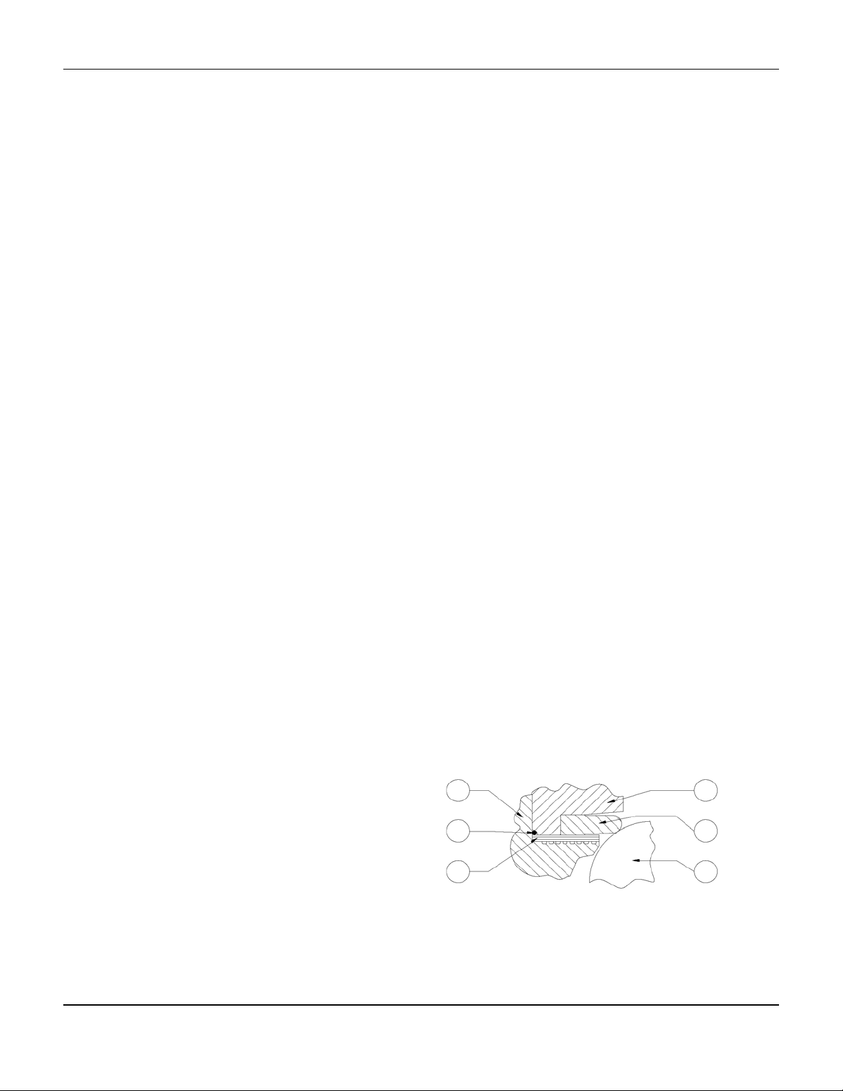
Figure 1. Section view of Heavy Duty
Composition (TCM) Ball Seal
22
23
21
-2-
Page 3

Mark V-100 SerieS Control ValVeS
Solid Ring Packing Continued,
1. Remove the actuator cover.
2. Remove the lever.
3. Disconnect the actuator and body cap screws
(key 4) and hex nut if used (key 5).
4. Remove the packing flange nuts (key 3), pack
ing flange, if used, and packing follower.
5. Remove the packing rings (key 6) with a formed
wire hook. To remove the TFE V-ring packing,
the wire hook should have a sharp end to allow
you to pierce the packing for removal.
6. Clean the packing box, all metal parts and com-
plete all required maintenance.
7. Replacing single packing
7.1 Replace the packing box ring
(key 18).
7.2 Next, replace the packing rings (key 6).
8. Replacing double packing arrangements
8.1 Replace the packing box ring
(key 18).
8.2 Replace one half of the total number of
packing rings (key 6).
8.3 Install the packing washer, if used.
8.4 Replace the lantern ring and the remain
ing packing rings.
8.5 If used, replace the packing
8.6 Install the packing follower (key 15)
8.7 Replace the packing flange, if used
8.8 Replace and tighten the packing flange
nuts until they are finger tight.
9. Reconnect the actuator following the previously
noted orientation.
10. Replace the cap screws (key 4) and hex nuts
(key 5) using the torques from table 6.
11. Follow the actuator instruction manual to com
plete the actuator assembly and to set the travel
adjustment.
12. After the valve is placed in service, the packing
flange nuts may require retightening to prevent
leakage.
Ball Seal or Flow Ring Maintenance
Caution must be used when working near the
V-ball. The V-Ball closes with a shearing, cutting motion and can cause personal injury or property damage if objects become caught in a closing valve. Be
sure to keep the path of the V-notch valve clear while
stroking the valve.
Disassembly:
1. Isolate the valve from the line.
1.1 It is necessary for the removed valve to
be positioned so that the seal
ring or flow ring is pointed upward
1.2 Ensure that V-ball (key 21) is in the open
position.
2. Remove the cap screws that secure the seal
protector ring in place.
3. Carefully remove the ring from the body,
ensuring that the surface of the ball is not nicked
or scraped.
4. Remove the O-ring (key 24), if used.
5. Mark the position of the ball seal and the valve
body, so that it can be returned to its
original position when it is reinstalled.
6. Carefully remove:
6.1 The bi-directional metal or TCM ball seal
(key 23)
6.2 The back-up ring
6.3 Shim seals
7. Clean all parts and inspect for damage.
Installation of Metal, Bi-directional Metal or
Heavy-Duty Composition (TCM) Ball Seal
1. Inspect the sealing surface of the valve body
for nicks and scratches that will prevent
the shims from sealing.
2. Turn the V-ball to the closed position and
install the appropriate number of shims
(Key 20) from table 3. For the bi-directional
metal ball seal, use a 1/1000-inch or 1/4 mm
thick test shim. A piece of paper would
be a suitable alternative.
Place the test shim across the ball face.
-3-
Page 4

Mark V-100 SerieS Control ValVeS
Installation of Metal, Bi-directional Metal or
Heavy-Duty Composition (TCM) Ball Seal
Continued,
3. Check for nicks and scratches on the ball seal,
sealing surface, and backup ring. Install the
ball seal and the backup ring on top of
the shim seals. If damage was
detected on any of the components, the
damage should be turned away from
the V-ball. Install the bi-directional ball
seals, to ensure proper orientation, use
the marks made in step number
5 of the removal.
4. Metal and TCM ball seals:
4.1 Install seal protector ring (key 22) on the
ball seal and shim seals (key 23 and key
20).
4.2 Secure the seal protector ring and the
ball seal to the valve body by threading
and tightening the capscrews. To obtain
the closest ball deflection to zero, add
and remove shim seals (key 20).
4.3 Zero ball seal deflection is when a .005
inch or 0.13 mm shim causes the seal to
be broken between the v-notched ball
and the ball seal. The parts must be
secure or an inaccurate zero will result.
5. Bi directional metal ball seals:
5.1 Install seal protector ring (key 22) on the
ball seal and shim seals (key 24 and key
20).
5.2 Secure the seal protector ring, ball seal
and shims (key 24 and 20) by threading
and tightening the capscrews (key 19).
5.3 Zero ball seal deflection can be tested
by removing the 1/1000 of an inch or
.025 mm thick test shim from under the
ball seal. If this is possible, remove the
seal protector ring, the ball seal, and the
back-up ring.
5.4 To check the zero deflection, remove
one shim, and assemble the
parts. Attempt to remove one 1/1000
inch or 0.025mm shim. If the shim is
neither too tight or too loose,
then zero deflection is obtained.
6. Once zero deflection is obtained remove:
6.1 The seal protector ring
6.2 The ball seal
6.3 The back up ring (if the bi-directional
metal seal is used)
6.4 The number of seals indicated in table
4.
6.5 For the bi-directional metal ball seal
leave at least one shim seal in the
body.
7. Install the ball seal and the backup ring, if one
is used.
8. For metal ball seals, install one shim seal (key
20) on top of the metal ball seal.
9. Install 0-ring (key 24), if used, into the body.
10. Ensure that the ball seal is centered on the V ball. For the bi-directional ball match orienta tion marks that were made in step 5 of the
removal section.
11. Install the seal protector ring (key 22) and
screw the cap screws and washers, (if used) to
secure the body.
Installation of Flow Ring
1. Ensure that the V-ball (Key 21) is in the closed
position. Replace the shim seals in the body
Table #3
2. Install the O-ring (Key 24) in the body and posi tion the flow ring to ensure that it is centered
and that it does not touch the v-ball.
3. Install the washers that hold the seal protector
and twist on the cap screws.
4. Check the minimum clearance of the flow ring
and the V-ball from table 5. Measure the exist
ing clearance and adjust to obtain the minimum
clearance by adding and removing shims.
-4-
Page 5

Mark V-100 SerieS Control ValVeS
Drive Shaft and V-Ball
Disassembly:
Caution:
Use care when removing the actuator lever, using
a wheel-puller if necessary. If the actuator lever is
forced off the valve shaft the ball could move from
the centered position, damaging the V-Ball, seal and
valve body.
Before disassembly, note the orientation of the actuator in relation to the body and note the orientation of the
lever in relation to the valve body.
1. Remove the actuator cover.
2. Remover the lever.
When the actuator is removed from the valve body,
the ball/shaft assembly may rotate and cause personal injury or damage to equipment. Prevent rotation
by turning the V-Ball to a stable position in the body.
3. Detach the valve from the line. It is necessary
for the removed valve to be positioned
so that the seal ring or flow ring is pointed
upward.
4. Unscrew the cap screws (key 19) that hold the
seal protector ring in place (key 22).
5. Carefully remove the ring from the body ensur-
ing that the surface of the ball is not nicked or
scraped
6. Remove the O-ring (key 24).
7 Remove the ball seal (key 23) from the ball seal
constructions.
8. Lift the shim seals (key 20).
9. Clean all parts and inspect for damage.
10. Remove packing flange nuts (key 3) and lift the
packing flange and follower (key 15) from the
packing box.
11. With a formed wire hook, remove the packing
rings.
12. Clean the packing box and all metal parts com-
plete all required maintenance.
13. Locate and remove the groove pin (key 10).
14. Unscrew the guidepost retaining nuts (key 14) or
the retainer, depending on valve body size.
15. Support the V-ball securely and remove the
guidepost, not allowing the guidepost to scratch
the seal.
16. Remove:
16.1 Guide post retainer (key 25)
16.2 Guide post (key 13)
16.3 Gasket (key 12)
16.4 Spring retainer washer (for sizes 3 inch
and larger).
17. The drive shaft is pushed into the body from the
bonnet. The drive shaft is aligned with
the guidepost bushing. (key 11)
18 Find the groove pin hole, noting that the V-Ball
has a raised flat surface on one side. To remove
the groove pin, place a punch on the side of the
ball opposite the raised flat surface and
drive the out pin (Key 10). See Figure 12.
19. Slip the drive shaft through the body out the
guidepost end. Remove the thrust washer.
20. Carefully remove the ball from the body ensuring
that the surface of the ball is not nicked
or scraped.
To remove the bearings (Keys 8 and 11) see Figure
5 for replacing the bearings. Refer to the bearing
replacement procedure. When a new body (Key 7)
and drive shaft bearing (Key 8) or V-Ball (Key 21) and
guide post bearing (Key 11) is ordered, the bearing
will be pressed in at the factory.
Assembly
1. Follow the instructions on the bushing replace
ment from this manual.
2. Carefully insert the V-ball in the body ensuring
the surface of the ball is not nicked or scraped.
Provide secure support for the V-ball.
While installing the drive shaft, hold the thrust
washer(s) (Key 9) between the drive shaft bearing
(Key 8) and the V-Ball (Key 21).
3. Slip the drive shaft into the guidepost end
through body.
4. Match the index mark on the shaft with index
mark on the V-ball.
-5-
Page 6

Mark V-100 SerieS Control ValVeS
Assembly Continued,
5. Gasket installation
5.1 2 In Body – Slip the gasket (key 12)
over the guide post (key 13) and
hold the wave spring, if used, between
the ball and the body. Insert
the guidepost assembly into the
body, wave spring, and ball valve.
5.3 3, thru 8 inch bodies - Slide both the
gasket (key 12) and the spring retainer
washer (if required) over the guide post
(key 13) and hold the wave spring, if
used, between the V-ball and the body.
Insert the guidepost assembly into the
body, wave spring, and ball valve.
6. Insert the retainer for the guidepost and secure
with retainer nuts; for body sizes 2-through
8 inch. Tighten nuts to the recommended
torque from table 1.
7. Insert groove pin (key 10) to lock the drive shaft
and V-ball connection. The pin should enter
from the large hole and go towards the
smaller diameter hole. The pin
should be flush with both ends.
8. Replace the packing box ring (key 18) and
install the new packing (key 6).
9. Install the packing follower (key 15) and replace
the packing flange if used. Replace and tighten
the packing flange nuts until they are finger
tight. When under actual flow conditions the
nuts will need additional tightening to
control leaking.
10. Following the instructions under ‘Ball Seal or
Flow Ring Maintenance”, replace the ball seal or
flow ring.
11. Reconnect the actuator using the actuator orien tation that was noted previously. The cap
screws (key 4) and hex nuts (key 5) should be
torqued to the values listed in Table 1.
12. Install the lever using orientation that was noted
previously and the identifying marks from figure
3.
13. Use the appropriate actuator instructions for
remaining mounting instructions and the travel
adjustment.
Bushing Replacement
Jordan Valve does not recommend replacing bushings
in the field. The procedure is difficult and may cause
permanent damage to the V-ball. If replacement of the
bushing in the field is necessary, follow the instructions
that follow and the dimensions in Figure 5.
Note:
Do not heat the valve in an attempt to ease the
replacement procedure of the body bushing. Heating the valve will cause the plastic-lined material to
release uorine gas, which is extremely hazardous,
causing; poisoning, suffocation, and burns.
Table 1, Recommended Bolt Torque
Key Number Body Size, Inches Bolt Torque
ft•lb N•m
2 27 37
Guide Post
Retainer Nut
Key 6
Cap Screw
Key 11
3 43 58
4 65 88
6 95 129
8 and 10 200 271
12 95 129
2-6 65 88
8-12 100 136
Taper Pinhole
Figure 2. V-Ball showing Groove Pin Hole
-6-
Page 7

Mark V-100 SerieS Control ValVeS
ACTUATOR
VALVE OPEN
MOUNTING STYLE
STYLE A
FLOW
(PDTC)
RIGHT
HANDED
STYLE B
(PDTO)
STYLE C
(PDTC)
FLOW
FLOW
LEFT
HANDED
STYLE D
(PDTO)
NOTES:
1. Arrow on lever indicates direction of actuator thrust to close valve
2. PDTC - push down to close; PDTO - push down to open
3. Right-hand mounting controls with V notch No. 1;
Left-hand mounting controls with V notch No. 2
4. For 60° operation with push down-to-close action
FLOW
ACTUATOR POSITION
1 2 3 3
(extending actuator rod closes valve). Rotate actuator lever clockwise
so that lever index mark is offset 1 spline tooth from valve shaft index
mark for 1/2" through 3/4" (12,7mm through 19,1 mm) valve shafts
and 2 spline teeth from valve shaft index mark for 7/8" (22,2mm) and
larger valve shafts
Figure 3. Index Marks for Actuator Lever Orientation
Body
Construction
Size
Inches
(1)
A
(1)
B
in. mm in. mm in. mm in. mm in. mm
2 4.88 124 2.19 56 8.25 206 8.50 216 9.25 235
3 6.50 165 3.00 76 10.12 270 11.12 282 11.50 292
Standard
4 7.62 194 3.12 79 11.44 290 12.12 308 13.62 346
6 9.00 229 4.00 102 13.62 346 14.38 365 16.50 419
8 9.56 243 5.75 146 13.62 346 15.38 391 17.12 435
10 11.70 297 6.28 160 16.75 425 19.38 492 ---
12 13.30 338 7.25 184 20.13 511 22.25 565 ---
1.Does not include gaskets
Figure 4. Required clearances for installation of
Mark V-100 Series Ball Valve Body
C
ASME Flanges
150 300 600
C A
B
28
-7-
Page 8

Body
Size,
IN
2
3
4
6
8
10
12
Mark V-100 SerieS Control ValVeS
Body Bushing Guide Post Bushing
A B RAMS
RAM 1 RAM 2 RAM 3 RAM 4
mm in. mm in. mm in. mm in. mm in. mm in. mm in. mm in. mm in. mm in.
15.37 0.60 25.40 1.00 12.70 .500 19.05 .750 80.84 3.183
15.11 .595 24.89 .980 12.45 .490 18.80 .740 80.79 3.181 19.56 .770 15.62 .615
21.72 .855 31.75 1.25 19.05 .750 26.44 1.041 117.17 4.613
21.46 .845 31.24 1.230 18.80 .740 26.19 1.031 117.09 4.610 29.21 1.150 23.50 .925
24.89 .980 34.93 1.375 22.23 .875 29.59 1.165 141.81 5.583
24.64 .970 34.42 1.355 21.97 .865 29.34 1.155 141.73 5.580 32.26 1.270 26.67 1.050
28.07 1.105 41.28 1.625 1.000 1.00 34.37 1.353 190.12 7.485
27.81 1.095 48.77 1.605 .990 .990 34.11 1.343 190.02 7.481 37.08 1.460 31.50 1.240
34.42 1.355 49.23 1.938 31.75 1.25 40.72 1.603 233.76 9.207
34.16 1.345 48.72 1.918 31.50 1.24 40.46 1.593 233.76 9.203 43.43 1.710 37.85 1.490
34.42 1.355 49.23 1.938 31.75 1.25 40.72 1.603 287.50 11.319
34.16 1.345 48.72 1.918 31.50 1.24 40.46 1.593 287.38 11.314 43.43 1.710 37.85 1.490
40.77 1.605 53.96 2.125 38.10 1.50 45.54 1.793 345.39 13.598
40.51 1.595 53.47 2.105 37.85 1.49 45.29 1.783 345.26 13.593 48.13 1.895 42.57 1.676
1& 2 C D
E (min.) A
19.81 .780
114 4.5
29.46 1.160
146 5.75
32.51 1.280
152 6
37.34 1.470
165 6.5
43.69 1.720
191 7.5
43.69 1.720
191 7.5
48.39 1.905
216 8.5
29.92 1.06
36.51 1.44
39.69 1.56
44.45 1.75
50.8 2
50.8 2
55.56 2.19
B RAMS 3
& 4
15.88 .625
23.75 .935
26.92 1.060
31.75 1.250
38.10 1.500
38.10 1.500
42.82 1.686
E (min.)
25 1.0
38 1.5
38 1.5
51 2.0
51 2.0
51 2.0
51 2.0
Drive out used
Drive shaft busing
(use RAM 1)
RAM 1
Drive shaft bushing
RAM 2
Drive in new
Drive shaft bushing
(Use RAM 2)
Figure 5. Ram Dimensions for replacing Bearings
Drive out guidepost busing use RAM 3
Drive in guidepost bushing use RAM 4
E
MIN
BA
RAM 3 and 4
Support shoulder when
installing or removing
guidepost bushings
E
A
0.25
B
RAM 1
Guide post retainer shoulder of valve body
2.0
MIN
A
RAM 2
D 0.25
B C
RAM shoulder
NOTE:
When driving in a new drive shaft bushing
the shoulder of RAM 2 will bottom on the
valve body guidepost retainer shoulder
-8-
Page 9

Mark V-100 SerieS Control ValVeS
Body Bushings
1. Follow the instructions for disassembly in the
“Drive Shaft and V-Ball Disassembly” section of
this manual.
2. From figure 5 select the proper size ram and
insert it in the body. This will allow you to drive
out the bushing with a hydraulic press.
3. Apply a suitable lubricant to the outside diameter
of the bushing. Jordan Valve recommends the
lubricant Moly-Kote.
4. To install the bushing:
4.1 Place the bushing in the bushing bore
4.2 Ensure that the bushing lead is in the
chamber is turned toward the bushing
bore.
4.3 2 thru 8 inch –drive the bushings into the
body using ram 2. The bushing is in the
suitable position when larger shoulder on
the ram contacts the valve body.
5. Follow the assembly instruction in the Drive shaft
V-Ball section of this manual.
Guide Post Bushing
Parts Ordering
Each V-Ball Valve Body assembly is assigned a serial
number, which can be found on the nameplate. Refer to this serial number when contacting your Jordan
Valve representative.
When ordering replacement parts, specify the serial
number, key number, and part description, from the following Parts Lists.
Repair Kits
Recommended spare parts for TCM or stainless steel
ball seal constructions are available as complete kits.
Gasket material is composition for temperatures up
to 450°F (232°C). Packing is PTFE and carbon filled
PTFE in single arrangements for standard packing box
depth. Since most original shim seals can be re-used
during repair, kits include fewer shim seals than are
originally furnished.
1 Follow the instruction for the removal of the V-Ball
in the “Drive Shaft and V-Ball disassembly” sec-
tion of this manual.
2. Ensuring that the ball is properly supported,
insert the proper ram size 1. Without proper sup port, the ball can be permanently damaged.
3. Remove the old bushing using a hydraulic press.
4. Apply a suitable lubricant to the outside diameter
of the bushing. Jordan Valve recommends the
lubricant Moly-Kote.
5. To install the bushing
5.1 Place the bushing in the bushing bore.
5.2 Ensure that the bushing lead in chamber
is turned toward the bushing bore.
6. The bushing can be installed with a ram that is
larger than the outside diameter than of
the bushing. Using this type of ram will ensure
that the bushing is inserted correctly. Bushings
that are improperly installed may cause
equipment damage.
7. Support the ball as indicated in figure 5. Push
the new bushing in flush with the ball ear.
8. Follow the ‘Drive Shaft and V-Ball
Maintenance’ section of this manual to the valve.
Mark V100 with Mark 67CFR Regulator
-9-
Page 10

Mark V-100 SerieS Control ValVeS
1
2
3
4
5
6
7
8
9
10
11
12
13
15
16
17
18
19
20
21
22
23
24
25
14
Figure 6. Typical Cross Section of 2-8 inch Mark V-100 Series Ball Valve
-10-
26
Page 11

Mark V-100 SerieS Control ValVeS
Parts List
Key No. Description Part Number
2-inch, shaft diameter 1/2” (12.7 mm) 38A6130X012
3-inch, shaft diameter 3/4” (19.1 mm) 38A6132X012
1 Drive Shaft
17-4PH SST
2 Packing Flange Stud
(2 req’d)
3 Packing Flange Nut
(2 req’d)
4 Cap Screw, pl steel
5 Hex Nut, pl steel (2 req’d) 1A377224112
6 Single Arrangements
7 Valve Body See Following Table
8 Drive Shaft Bearing See Following Table
4-inch, shaft diameter 7/8” (22.2 mm) 38A6123 X012
6-inch, shaft diameter 1” (25.4 mm) 38A6122 X012
8-inch, shaft diameter 1-1/4” (31.8 mm) 38A6125 X012
10- inch, shaft diameter 1-1/4” (31.8mm) 38S6125X012
12- inch, shaft diameter 1-1/4” (31.8mm0 39A8177X012
2” and 3” 1E9441X0012
B7M Steel
B8M Strain Hardened SST
B7M SS Steel Flange
Studs
B8M Steel Flange Studs
2” (2 req’d) 1A361624052
3” (2 req’d) 1A340924052
4” and 6” (4 req’d) 1A340924052
8”, 10”, and 12” (4 req’d) 1A544424052
PTFE / Composition Ring
Grafoil
4” and 6” 12A8835 X012
8” and 10” 12A8950 X032
12” 12A8926X032
2” and 3” 1E9441 35222
4” and 6” 12A8835 X022
8” and 10” 12A8950 X022
12” 12A8926X022
2” and 3” 1E9440X0012
4” and 6” 1A3753X0012
8”, 10”, and 12” 1A3412X0012
2” thru 3” 1E944035252
4” and 6” 1A375335252
8”, 10”, and 12” 1A341235252
2" 12A9016 X012
3" 12A8995 X012
4" 13A2604 X012
6" 12A8832 X012
8" and 10" 12A8951 X012
12" 12A8935X022
2" 12A9134 X012
3" 12A9136 X012
4" 14A4920 X012
6" 12A9137 X012
8" and 10" 12A9138 X012
12" 12A9139X012
-11-
Page 12

Mark V-100 SerieS Control ValVeS
Parts List
Key No. Description Part Number
2” 13A2518 X012
3” (2 req’d) 13A2570 X012
9 Thrust Washer 316 SST
10 Groove Pin, 316 SST
11 Guide Post Bushing See Following Table
Composition 2" 13A2521 X062
12 Gasket
316 SS 2" 13A2544 X012
13 Guide Post
14 Retainer Nut See Following Table
15 Packing Follower, CF8M (316 SST)
16 Drive Screw, SST (2 req’d) 1A3682 28982
17 Name Plate, SST 15A0460X012
4” (2 req’d) 13A2590 X012
6” (2 req’d) 13A2624 X012
8” (2 req’d) 13A2651 X012
10” (2 req’d) 13A2651X012
12” (2 req’d) 13A2680X012
2" 18A6134 X012
3" 18A6135 X012
4" 18A6136 X012
6" 18A6137 X012
8" and 10" 18A6138 X012
12" 19A8176X012
3" 13A2573 X062
4" 13A2593 X062
6" 13A2627 X062
8" and 10" 13A2654 X012
12" 13A2683X052
3" 13A2562 X012
4" 13A2582 X012
6" 13A2616 X012
8" and 10" 13A2642 X012
12" 13A2675X012
2" 16A6078 X012
3" 26A6080 X012
4" 27A4113 X012
6" 26A6077 X012
8" and 10" 26A6081 X012
12" 26A6088X012
-12-
Page 13
Mark V-100 SerieS Control ValVeS
Parts List
Key No. Description Part Number
2” 16A6082X012
3” 16A6084X012
18 Packing Box Ring 316 SST
19 Screw, pl steel
(2 req’d)
TCM Ball Seal, 12 req’d
20 Shim Seal, 316 SST
Metal Ball Seal, 12 req’d
21 V- Ball
22 Seal Protector Ring See Following Table
4” 17A5692X012
6” 16A6085X012
8” and 10" 16A6086X012
12" 16A6087X012
2" 1L545428982
3" and 4" 1U7648X0012
6" and 8" 1A560724052
10" and 12" 14A5403X012
2" 17A1965X012
3" 17A1966X012
4" 17A1967X012
6" 17A1968X012
8" 17A1969X012
10" 17A1970X012
12" 17A1971X012
2" 13A2545X022
3" 13A2564X022
4" 13A2584X022
6" 13A2618X022
8" 13A2644X022
10" 13A2661X012
12" 13A2676X012
2" 38A6211X042
3" 38A6124X052
4" 38A6131X052
6" 48A6129X052
8" 48A6128X052
10" 48A6127X052
12" 49A8178X052
-13-
Page 14

Mark V-100 SerieS Control ValVeS
Parts List
Key No. Description Part Number
2" 13A2546 X012
3" 13A2565 X012
4" 13A2585 X012
TCM
23 Ball Seal
Metal, 316 SST
24 O-Ring, PTFE
25 Guide Post Retainer
26 Retainer Stud See Following Table
27* Pipe Plug, 316 SST (Not Shown) 1A767535072
28* Line Studs (Contact Jordan Valve Sales Representative) ---
29* Cap Screw, pl steel (2 req’d) 6" 1F960324052
30* Washer or Stop Nut, pl steel (2 req’d) 6" (Washer) 1B865928982
31* Nameplate (Not Shown) 13B2599X012
32* Wire (Not Shown) (For valve purchased without actuator) 16A3188X012
33* Gasket, 316 SST/Graphite 6" 1U1805X0012
*-Not Shown
CF8M Valve Body
6" 13A2619 X012
8" 13A2645 X012
10" 13A2662X012
12" 13A2677X012
2" 14A1758X012
3" 14A1759X012
4" 14A1760X012
6" 14A1761X012
8" 13A1762X012
10" 13A2703X012
12" 13A2704X032
2" 14A1345X012
3" 14A1346X012
4" 14A1347X012
6" 14A1348X012
8" 14A1349X012
10" 14A5406X012
12" 14A5407X012
2" 13A2542X022
3" 13A2559X022
4" 13A2581X022
6" 13A2613X022
8" and 10" 23A2639X022
12" 23A2673Z022
8" 1D770424052
8" (Stop Nut) 1V136228982
8" 1U1804X0022
-14-
Page 15

Mark V-100 SerieS Control ValVeS
Parts List
Key 7, Valve Body
Body
Size,
Inches
2 43A2538 X0B2 43A2538 X0C2
3 43A2555 X0B2 47A5684 X0C2
4 43A2577 X0B2 43A2577 X0C2
6 43A2609 X0B2 43A2609 X0C2
8 43A2635 X0B2 43A2635 X0C2
10 Contact Jordan Valve Contact Jordan Valve
12 Contact Jordan Valve Contact Jordan Valve
Key 8, Main Shaft Bushing
Body
Size,
Inches
2 17A1696 X072 17A8654 X012 17A8655 X012 17A8656 X012
3 18A6091 X072 18A6416 X012 18A6147 X012 18A6148 X012
4 18A6096 X072 18A6149 X012 18A6150 X012 18A6151 X012
6 18A6120 X072 18A6152 X012 18A6153 X012 18A6154 X012
8 and 10 18A6107 X072 18A6155 X012 18A6156 X012 18A6157 X012
12 18A6120 X072 18A6158 X012 18A6159X012 18S6160 X012
PTFE/Composition
CF8M LCC
Standard Packing Box
316 SS
440C SS
Lining
Alloy 6
(CoCr-A)
Silver Plated
CoCr-A
Key 11, Guide Post Bushing
Body
Size,
Inches
2 13A2534 X192 14A6653 X012 15A0427 X012 15A0424 X012
3 13A2572 X192 15A0435 X012 15A0437 X012 15A0436 X012
4 13A2592 X152 15A0441 X012 15A0443 X012 15A0442 X012
6 13A2626 X122 15A0445 X012 14A7278 X012 14A8579 X012
8 and 10 13A2653 X172 15A0449 X012 15A0451 X012 15A0450 X012
12 13A2682 X092 15A0455 X012 15A0457 X012 15A0456 X012
316 SS
PTFE/Composition
Lining
440C SS
-15-
Alloy 6
(CoCr-A)
Silver Plated
CoCr-A
Page 16

MKV-100IM/0314/2K
Mark V-100 SerieS Control ValVeS
Parts List
Key 14 & 26, Retainer Nut and Retainer Stud
Body
Size,
Inches
Nut (Key 14) Stud (Key 26) Nut (Key 14) Stud (Key 26)
2 1A3772 24072 1F4380 X0032 1A3773 X0052 1F4380 X0012
3 1A3374 24072 1A8441 X0042 1A3374 X0052 1V8441 X0022
4 1A3772 24072 1A4207 35222 1A3772 X0032 1A4207 X0012
6 1C3306 24072 1H2597 35222 1C3306 X0052 1H2697 X0032
8 and 10 1A3520 24072 1B9588 X0032 1A3520 X0022 1B9588 X0012
12 1E9446 35072 1H2597 35222 1E9446 X0012 1H2597 X0032
Key 22, Seal Protector Ring
Body
TCM Ball Seal Metal Ball Seal
Size,
Inches
316 Stainless Steel 316 Stainless Steel
2 17A8650 X022 17A8649 X022
3 27A1987 X022 24A1748 X022
4 27A1988 X022 24A1749 X022
6 27A1986 X022 24A1750 X022
8 27A1985 X022 24A1751 X022
10 37A1972 X022 33A2690 X022
12 37A1973 X022 33A2705 X022
B8M Stainless Steel B7M Steel
Jordan Valve, a division of Richards Industries
3170 Wasson Road • Cincinnati, OH 45209
513.533.5600 • 800.543.7311 • 513.871.0105 (f)
info@richardsind.com • www.jordanvalve.com
 Loading...