

Page 1
I & M Mark 608 (1-1/2” - 2”)
3170 Wasson Road • Cincinnati, OH 45209 USA
Phone 513-533-5600 • Fax 513-871-0105
[email protected] • www.jordanvalve.com
Installation & Maintenance Instructions for
Mark 608 Gas Pressure Regulators
Warning: Jordan Valve Pressure Regulators must only be used, installed and repaired in accordance with these Installation & Maintenance Instructions. Observe all applicable public and company codes and regulations. In the event
of leakage or other malfunction, call a qualified service person; continued operation may cause system failure or a
general hazard. Before servicing any valve, disconnect, shut off, or bypass all pressurized fluid. Before disassembling
a valve, be sure to release all spring tension.
Please read these instructions carefully!
two end threads clean. Jordan uses, and recommends, thread sealer Teflon ribbon.
Your Jordan Valve product will provide you with long,
trouble-free service if it is correctly installed and maintained. Spending a few minutes now reading these instructions can save hours of trouble and downtime later.
When making repairs, use only genuine Jordan Valve
parts, available for immediate shipment from the factory.
6. The flow arrow on the valve body must be pointed
in the direction of flow. Ideally, the valve should be
installed in the highest horizontal line of piping to
provide drainage for inlet and outlet piping, to prevent water hammer, and to obtain faster response.
7. If possible, install a relief valve downstream from
the valve. Set at 15 psi above the control point of
Ideal Installation
the valve.
8. In gas service, expand the outlet piping at least
one pipe size if the control pressure (downstream)
Main Line
3
4
1
2
4
1
1
5
R
is 25% of the inlet pressure or less. A standard
tapered expander connected to the outlet of the
valve is recommended.
9. Where surges are severe, a piping accumulator is
recommended.
Control Line
1
1. Shut off Valve
2. Jordan Regulator
3. Strainer and Drain Valve
4. Pressure Gauge
5. Relief Valve
1. To protect the valve from grit, scale, thread chips
and other foreign matter, ALL pipelines and piping
components should be blown out and thoroughly
cleaned before the installation process begins.
2. Shutoff valves, pressure gauges and by-pass piping
should be installed as indicated in the Ideal Installation Schematic to provide easier adjustment, operation, and testing.
3. A line strainer should be installed on the inlet side
of the valve to protect it from grit, scale and other
foreign matter. A 0.033 perforated screen is usually
suitable for this purpose. Line strainers are available from Jordan Valve.
4. For best control, 3’ 0” straight sections of pipe
should be installed on either side of the valve.
5. In preparing threaded pipe connections, care
should be exercised to prevent pipe-sealing compound from getting into pipelines. Pipe-sealing
compound should be used sparingly, leaving the
A control line must be installed as follows:
1. Connect one end of a ¾” pipe to the fitting under
the diaphragm.
2. Connect the other end to an appropriate fitting on
the tank.
3. DO NOT locate the control line tap in any location
where turbulence or abnormal velocities may occur.
4. The control line should be sloped away from the
valve.
5. Install a pressure gauge to measure pressure in the
tank itself, not in the outlet piping or the control line
to aid in setting the valve.
Page 2
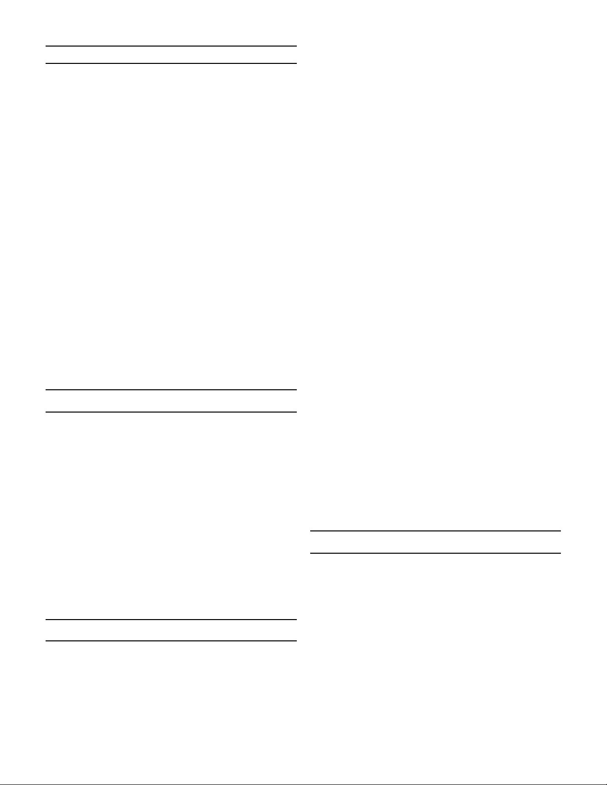
Control Line Piping Recommendation
Keep the regulator as close to the tank as possible
and as high as possible.
Minimize the length of the downstream pipe com-
ing from the valve.
NEVER reduce the pipe size on the valve outlet to
the tank. This line must always be as large as the
valve size, or one pipe size larger to assure it does
not act as a restriction.
Any downstream isolation valve after the regulator
must be a full port type. The isolation valve cannot
act as a restriction.
The sensing line must be a minimum of 3/4” pipe.
A sensing line isolation valve is recommended.
Again, must be full ported.
Slope the sensing line to the sensing port on the
tank.
Keep the sensing line as short and straight as pos-
sible.
For each 10 feet of sensing line, increase the line
size by one pipe diameter. (Especially important on
the blanket pressures of less than 5 inches of water
column).
Keep the sensing port on the tank as far removed
as possible from the downstream pipe outlet going
into the tank.
Start-Up
With the inlet, outlet, and bypass shutoff valves closed,
and no pressure in the downstream line:
1. Fully open the control line shut-off valve.
2. Fully open the outlet shut-off valve.
3. Slowly open the inlet shut-off valve.
4. Slowly open the inlet valve just enough to start flow
through the valve. Observe the downstream pressure gauge. Increase the downstream pressure
slowly by gradually opening the inlet valve.
5. Do not fully open the inlet valve until you are sure
that the regulator has control of the system. Usually, the handwheel on the inlet valve will turn freely
when this is achieved.
6. To change the controlled pressure, adjust the
controlled pressure supplied to the top of the diaphragm.
pressure increases after valve closes.
C. Pressure Fluctuates: Controlled pressure rises and
falls, will not settle out under low loads.
The next step is to determine what could cause the
trouble. The third step is to locate and remedy the cause
by the process of elimination. Make no assumptions and
check the easy ones first. The guide below lists the controlled pressure action, common causes and procedure
for checking each cause.
Controlled pressure action UNDER PRESSURE:
Valve undersized for application. Check capacity
required and valve capacity.
Line strainer screen clogged. Blow down strainers
or visually check that they are clear.
Incorrect setting on range spring. Vary the setting
and check response.
Main valve diaphragm or balance diaphragm rup-
tured. See action on valve maintenance.
Malfunction of other piping components. Check
for leaking safety valves, inadvertently opened or
closed valves.
Controlled pressure action OVER PRESSURE:
Incorrect setting on range spring. Vary the setting
and check response.
Main valve seats leaking. Close inlet shut-off valve,
allow downstream pressure to bleed off, close outlet valve and remove loading pressure tubing. Back
out adjusting screw on valve until free. Crack open
inlet shut-off valve - if the fluid issues from the main
valve port, the main valve seats are leaking.
By-pass shut-off leaking. During period of leakage
close outlet shut-off valve, observe downstream
pressure gauge.
Controlled Pressure Fluctuates:
Valve oversized. Check capacity required and valve
capacity.
Maintenance
Caution: Ensure that the valve is de-pressurized before loosening any fittings or joints. The following
steps are recommended before performing any maintenance on the valve:
Trouble Shooting
The first step in troubleshooting a piloted pressure regulator is to classify the action of the controlled pressure
into one of the following categories:
A. Under Pressure: Controlled pressure too low; not
enough flow or no flow through valve.
B. Over Pressure: Valve will not close or controlled
1. Allow pressure to bleed off through the downstream piping. Do not attempt to reverse the flow
through the valve by bleeding pressure from the
upstream from the upstream side of the valve.
2. When the pressure gauges indicate that all pressure has been removed from the system, close the
outlet shut-off valve and the valve may be serviced.
Note: Refer to the drawing at the end of this document for description and proper orientation of parts.
-2-
Page 3
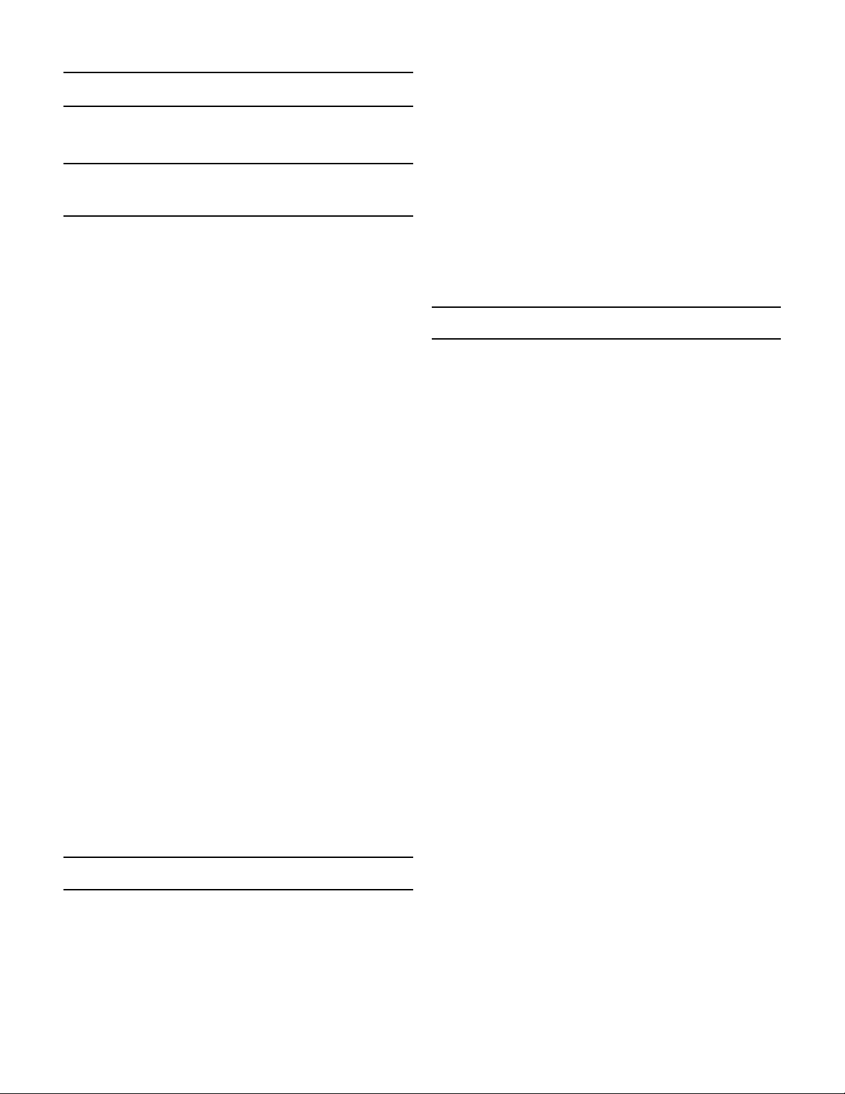
Main Valve
All operations can be performed with the valve in the
line.
Replacing the Main and Balance
Diaphragms
1. Remove the closing cap (1).
2. Thread the adjusting screw (2) out of the spring
tube.
3. If the set range is in psi, remove the upper spring
guide (not shown).
4. Remove range spring (3).
5. Remove the actuator flange bolts (8) and nuts (9).
6. Remove the upper case (5).
7. Insert special tool (Jordan Part Number 15522) into
the inlet of the valve and engage the hole in the
lower stem (23).
8. Loosen the diaphragm bolt (17).
9. Remove the spring guide (4), diaphragm plate
(6), main diaphragm (7), seal washer (30), and the
thread seal washer (31). Discard the main diaphragm.
10. Remove the ring nut (11), the lower diaphragm case
(10), and stem bushing (13), and o-ring (12). Jordan
recommends that the stem bushing and o-ring be
discarded and replaced with new parts when this
maintenance is performed.
11. Loosen hex bolts (26) and lockwashers (27). Remove the bonnet (14), two o-rings (24), and the
bonnet plate (15). Jordan recommends that these
o-rings be discarded and replaced with new parts
when this maintenance is performed.
12. Using the adjusting tool in the inlet of the valve, remove the upper stem (29) with tool number 70080-
111.
13. Remove the balance diaphragm plate (28), balance
diaphragm (25), and the thread seal washer (31).
Discard the balance diaphragm.
14. Using new replacement parts, reverse the above
procedure to reassemble. Lubricate o-rings prior
to installation with a suitable lubricant such as Dow
Corning #4 grease. Save the special tools provided with the repair kit for future use.
4. Install the new lower stem (17,18,19,20,23), plug
and seat assembly into the body.
5. Lubricate the new seat o-ring (21) prior to installation with a suitable lubricant such as Dow Corning
#4 grease. Install the o-ring (21) over the threads
and on to the seat (22).
6. Install the seat (22) over the lower stem (23). Carefully thread it into the body (16).
7. Use the seat removal tool to tighten the seat. Do
not over tighten! Compressing the seat o-ring into
the body bore is all that is required to produce a
seal.
8. Proceed to stem 14 in the section on replacing
main and balance diaphragms.
Ordering Spare Parts
Use only genuine Jordan Valve parts to keep your valve
in good working order. So that we can supply the parts,
which were designed for your valve, we must know exactly which product you are using. The only guarantee to
getting the correct replacement parts is to provide your
Jordan Representative with the valve serial number. This
number is located on the valve identification tag. If the
serial number is not available, the parts needed for your
valve might be determined using the following information: Model Number; Valve Body Size; Plug Material and
Seat Size; Spring Range or Set Point; Trim Material; Part
Name - Number and Quantity (see parts list chart).
NOTE: Without a valve serial number, any parts ordered
incorrectly are subject to a minimum 25% restocking
charge when returned.
Plug & Seat Replacement
1. Perform all steps in the section on replacing main
and balance diaphragms.
2. Use seat removal tool (Jordan Part Number 15533-
110) to remove the seat (22), and the lower stem,
plug and seat (17,18,19,20,23).
3. Remove the seat o-ring (21). Jordan recommends
that this o-ring be discarded and replaced with a
new one when this maintenance is performed.
-3-
Page 4
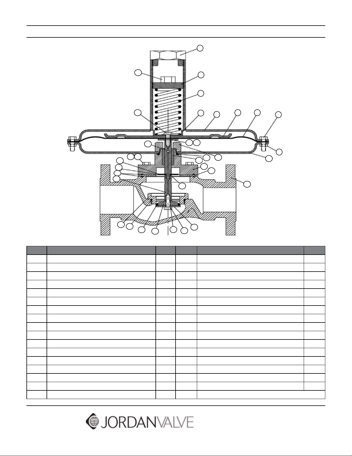
Illustration and Parts List
1
32
17
29
27 26
28
25
24
23
31
22
21
19
20
31
17
2
3
4
5
3130
11
12
13
14
15
18
6
7
16
8
9
10
Item Description Qt y. Item Description Qty.
1 Closing Cap 1 **17 HHCS 2
2 Adjusting Screw 1 **18 Seat Plate 1
3 Range Spring 1 **19 Soft Seat 1
4 Spring Guide 1 **20 Plug Face 1
5 Actuator Case (Upper) 1 *21 O-Ring 1
6 Main Diaphragm Plate 1 *22 Seat 1
7 Main Diaphragm 1 **23 Lower Stem 1
8 Hex Bolt 22 *24 Bonnet Plate O-Ring 2
9 Hex Nut 22 *25 Balance Diaphragm 1
10 Actuator Case (Lower) 1 26 HHCS 4
11 Ring Nut 1 27 Lockwasher (not shown) 4
*12 O-Ring 1 28 Balance Diaphragm Plate 1
*13 Stem Bushing 1 29 Upper Stem 1
14 Bonnet 1 30 Seal Washer, Large 1
15 Bonnet Plate 1 31 Seal Washer (not shown) 3
16 Body 1 32 Adjusting Bolt 1
* Recommended Spare Parts ** Furnished as an assembly in repair kits.
3170 Wasson Road • Cincinnati, OH 45209 USA
Phone 513-533-5600 • Fax 513-871-0105
Bulletin IM-MK608-0115
[email protected] • www.jordanvalve.com
 Loading...