

Page 1

I & M Mark EW Series
3170 Wasson Road • Cincinnati, OH 45209
Phone 513.533.5600 • Fax 513.871.0105 (f)
info@richardsind.com • www.jordanvalve.com
Warning: Jordan Valve Control Valves must only be used, installed and repaired in accordance with these Installation & Maintenance Instructions. Observe all applicable public and company codes and regulations. In the event
of leakage or other malfunction, call a qualified service person; continued operation may cause system failure or
a general hazard. Before servicing any valve, disconnect, shut off, or bypass all pressurized fluid. Before disassembling a valve, be sure to release all spring tension.
IntroductIon
Contained in this manual are installation instructions,
maintenance procedures and parts information for the
Mark EW Series Valve Body designs EWD, EWS and
EWT. Refer to the appropriate manuals for instructions
for the accompanying actuator and additional accessories.
Trained or experienced personnel should carry out
operation and installation of all pressure equipment.
If you have any questions regarding the equipment,
contact your Jordan Valve representative.
InstallatIon
Exceeding the recommended pressure and temperature limits indicated on the nameplates of your Jordan
valve control valve, can result in personal injury and
property damage. Jordan Valve recommends the
installation of a relief valve to protect against overpressure situations.
The Mark EW Series valve bodies are designed to
meet specific conditions for fluid control, temperature,
pressure and pressure drop. The limiting factor on
these valves can be the body/trim material combinations. Do not install these valves in any other applications without first consulting with your Jordan Valve
representative.
During installation, Jordan Valve recommends the use
of a sling to protect the painted surfaces of the valve.
Position the sling to avoid damage to tubing and accessories.
1. Inspect the valves for shipping damage and
foreign debris while uncrating.
Installation & Maintenance Instructions for the
Mark EW Series Globe Style Control Valve
2. Ensure the pipeline is free of welding slag,
chips and other debris by blowing out the line
before installation.
3. Position the valve so the arrow on the valve
body is in the same direction as the pipeline
flow.
4. Specific orientation of the control valve as sembly is flexible, unless limited by the
seismic criteria. Normal positioning
is with the actuator vertical above the valve
body. Should a different position be required,
be aware that the result may be uneven valve
plug and cage wear, and inefficient opera tion of the control valve system. Also,
be aware that the actuator may need addi tional support. Consult Jordan Valve for further
information on orientation.
5. Always employ proper piping and welding
practices when installing the valve in the line.
If welding is required, internal elastomeric
parts may remain in place. If the valve
has buttwelding ends and composition
trim, remove the composition trim prior
to welding into the line.
6. For flanged bodies, install an appropriate gas
ket between the pipeline and valve body flang
es.
7. With leak-off bonnet construction, remove the
pipe plugs (Figure 1, Keys 14 and 23)
to connect the leak-off piping. To avoid an
interruption of service during inspection or
maintenance, install a three-valve bypass
around the control valve assembly.
8. Most Jordan valves are shipped with
the actuator already installed according to
customer specifications. If your actuator has
been shipped separately, refer to the appropri ate mounting instructions in the actuator
manual.
Page 2

Mark EW SEriES GlobE StylE Control ValVES
MaIntenance
Internal valve components are subject to normal deterioration and must be inspected and replaced as required.
The necessity of inspections and replacement of parts
will depend on the severity of service conditions. Inspections and maintenance must be carried out on a regularly scheduled basis.
To ensure the safety of personnel and to protect against
property damage, the following steps should be carried
out before beginning disassembly.
1. To prevent the valve from opening suddenly,
disconnect any operating lines to the actuator.
This would include air pressure, electrical power
or control signal lines.
2. Isolate the valve by using the bypass valve or by
shutting down the process completely. Relieve
the pressure and drain the process fluid
from both sides of the valve.
3. Relieve the pressure contained in the actuator
by venting the actuator loading pressure
and relieving any power actuator spring
compression.
4. Lock-out procedures should be strictly adhered
to while the equipment is being serviced.
Packing Maintenance
This section provides instruction for maintenance of TFE
V-Ring packing. If your Jordan Valve Mark EWD, EWS
or EWT Control Valve uses graphite laminate or filament packing, refer to the appropriate manuals. Refer to
Figure 2 for appropriate key numbers unless otherwise
indicated.
For packing that is spring-loaded single TFE V-ring
packing, a sealing force is maintained by the spring
(Figure 1, Key 5). If leakage around the packing follower
(Figure 1, Key 3) is detected, tighten the packing flange
nuts (Figure 1, Key 16). If this does not stop the leakage,
refer to the Replacing Packing section of this manual.
With packing that is other than spring-loaded, unwanted
leaking can be limited by tightening the packing flange
nuts to create a stem seal.
If leakage occurs from the inside diameter of the packing, and tightening the flange nuts does not stop the
leaking, the valve stem may be worn or nicked. If the
leakage originates from the outside diameter of the
packing, the leakage may be caused by nicks and
scratches around the packing box wall. While performing the following procedures, carefully inspect the valve
stem and packing box wall for imperfections.
Also, anytime that a gasket seal is removed or disturbed,
a new gasket should be installed during reassembly,
ensuring a proper seal.
The following instructions include packing maintenance,
trim replacement and lapping of metal seats.
Adding Packing Rings
If using packing with a lantern ring (Figure 1, Key 5),
packing rings may be installed above the lantern ring as
a temporary measure, which does not involve removing
the actuator from the valve body.
1. Remove the packing flange nuts (Figure 2, Key
16) and lift the packing flange and follower (Fig
ure 2, Keys 20 and 3) away from the valve body.
2. Old packing rings that have been installed on
top of the lantern ring may be removed,
but use caution to avoid any damage to the
valve stem or packing box wall. All metal parts
should be cleaned to remove any grit that would
prevent the packing from creating a seal.
3. If split-ring packing is being used, spread the
rings over the valve stem and slide them into the
packing box.
4. If solid-ring packing is used, take off the stem
connector and slip the rings over the end of the
valve stem.
-2-
Page 3

Mark EW SEriES GlobE StylE Control ValVES
Adding Packing Rings Continued,
5. After replacing the packing flange and packing
follower, tighten the packing flange nuts
(Figure 2, Key 16) just far enough to prevent
leakage under operating conditions.
6. If the valve-actuator stem connection was
disassembled during this process, refer
to the actuator manual for reassembly
instructions.
7. While returning the valve to service, monitor for
leakage around the packing follower. If required,
retighten the packing flange nuts.
Replacing Packing
Note: Prior to performing this procedure, isolate
the control valve from all line pressure and release
the pressure from both sides of the valve. Drain the
process media and release all pressure from the
actuator. Practice lockout procedures during the
operation.
1. Remove the operating lines from the actuator as
well as any leak-off piping from the bonnet.
2. Disconnect the stem connector and unscrew the
yoke locknut (Figure 2, Key 17) to remove the
actuator from the valve body.
3. Loosen the packing on the valve stem by
unscrewing the packing flange nuts (Figure 2,
Key 16). Remove all travel indicator parts and
stem locknuts from the valve stem threads.
Note: When lifting the bonnet (Figure 2, Key 18), it is
very important to ensure that the valve plug and stem
assembly remain in the valve and on the seat. If the
assembly were to drop out after being partially lifted,
damage to the seating surfaces would result. Parts
are also easier to handle in this way.
4. Remove the hex nuts (Figure 4, Key 39) holding
the bonnet and body together, and lift
the bonnet off of the valve stem.
5. When lifting the bonnet, if the valve plug and
stem assembly begin to lift as well, use a brass
or lead hammer
and lightly tap on the end of the stem to
release them.
6. Place the bonnet on a protective surface to pre-
vent damage to the surface of the bonnet
gasket.
7. Remove the bonnet gasket (Figures 3 and 4,
Key 33) and cover the valve body opening in or
der to prevent debris from entering the
body cavity and to protect the gasket surface.
8. Remove the following parts (Figure 2):
a. packing flange nuts (Key 16)
b. packing flange (Key 20)
c. upper wiper (Key 2)
d. packing follower (Key 3)
9. Use a rounded rod to push out the remaining
packing parts from the body side of the
bonnet. Be careful not to scratch the packing
box wall. Clean the packing box and metal
packing parts.
10. Inspect the valve stem threads and packing
box surfaces for any edges which might
cut the packing. Any defects could create leak
ing in the packing box and damage to
the new packing. If any surface nicks or
burrs cannot be improved by light sanding
replace the damaged parts.
11. Remove the covering which protects the body
covering and install a new bonnet
gasket (Figures 3 and 4, Key 33). Ensure that
the gasket seating surfaces are clean
and smooth.
Note: When the tightening procedures in Step 13 are
completed properly, the spiral wound gasket (Figures
3 and 4, Key 35) will be compressed enough to load
and seal the seat ring gasket (Figures 3 and 4, Key
36) and compress the edge of the bonnet gasket
(Figures 3 and 4, Key 33) and seal the body-to-bonnet
joint.
The lubricated stud bolt nuts (Figure 4, Key 39) can be
identified by the black film that coats the nut threads.
The bolting procedures in Step 13 will ensure that the
bolting threads are clean, and will evenly tighten the nuts
onto the studs in a crisscross pattern. Be sure to follow
the crisscross pattern since the tightening of one spiral
wound gasket may loosen an adjacent nut. Continue
repeating the pattern until each nut is tight, creating the
body-to-bonnet seal. Repeat this torquing procedure
once the operating temperature has been reached.
-3-
Page 4
Mark EW SEriES GlobE StylE Control ValVES
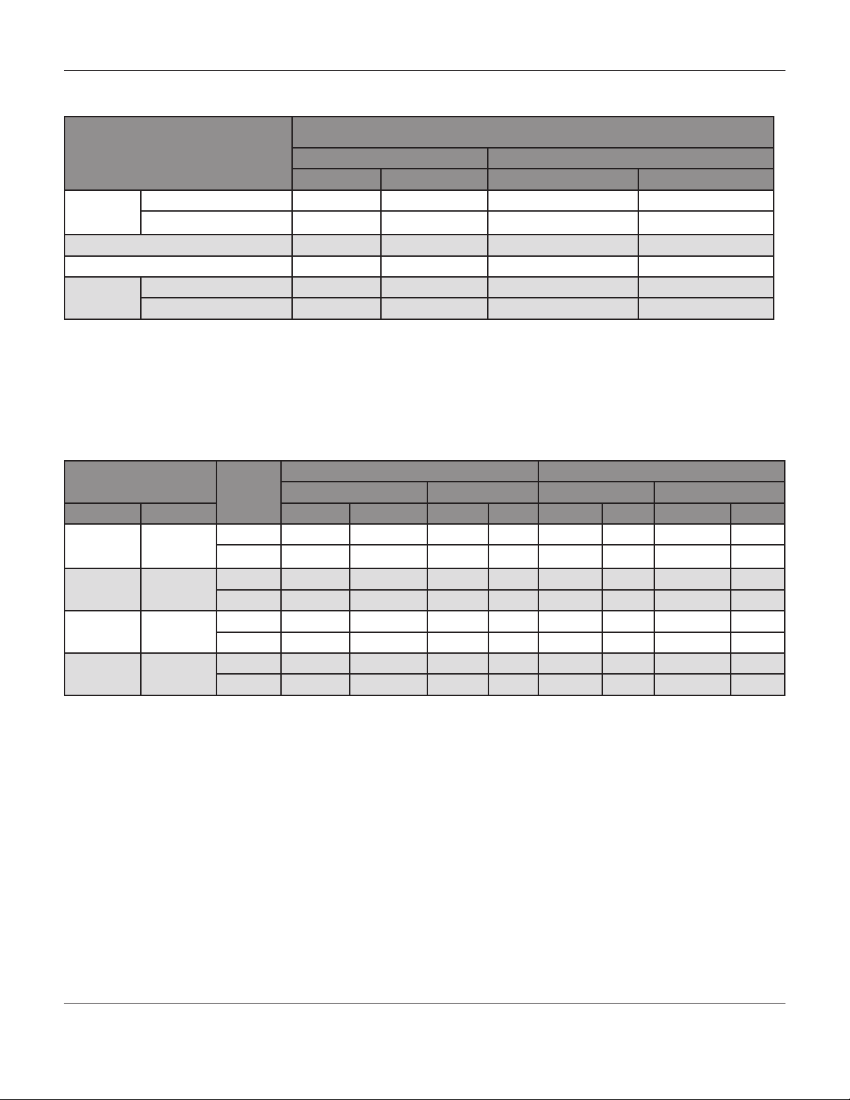
Table 1: Body-to-Bonnet Bolt Torque Guidelines
Bolt Torques
Body Size, Inches
Nonlubricated Bolting Stud Bolt Nuts Factory Lubricated
Ft•Lb N•m Ft•Lb N•m
8 x 6 Class 300 or 600 400 545 300 407
Class 900 970 1315 --- ---
12 x 6 400 545 300 407
10 x 8 550 745 --- ---
12 x 8 Class 300 or 600 540 732 --- ---
Class 900 2000 2712 --- ---
Table 2: Packing Flange Nut Torque Guidelines
Valve Stem Dia. ANSI
Class
Inches mm Lb•in N•m Lb•in N•m Lb•in N•m Lb•in N•m
1/2 12.7 300 28 3 42 5 59 7 88 10
600 39 4 58 7 81 9 122 14
3/4 19.1 300 64 7 95 11 133 15 199 23
600 87 10 131 15 182 21 274 31
1 25.4 300 108 12 162 18 226 26 339 38
600 149 17 223 25 310 35 466 53
1-1/4 31.8 300 152 17 228 26 318 36 477 54
600 209 24 314 36 437 49 655 74
PTFE Type Packing GRAPHITE Type Packing
Min. Torque Max. Torque Min. Torque Max. Torque
-4-
Page 5
Mark EW SEriES GlobE StylE Control ValVES
Packing Follower
Packing Ring
Lantern Ring
Packing Box Ring
R
R
**Garlock
*Grafoil
Upper Wiper
Packing Follower
Packing Ring
Lantern Ring
Packing Box Ring
Packing Ring
PTFE/Composition
R
*Grafoil
V - Ring
Upper Wiper
Packing Follower
Upper Wiper
Packing Follower
Female Adaptor
Female Adaptor
V - Ring
Male Adaptor
Lantern Ring
washer
Spring
Male Adaptor
Packing Box Ring
Lower Wiper
Packing Box Ring
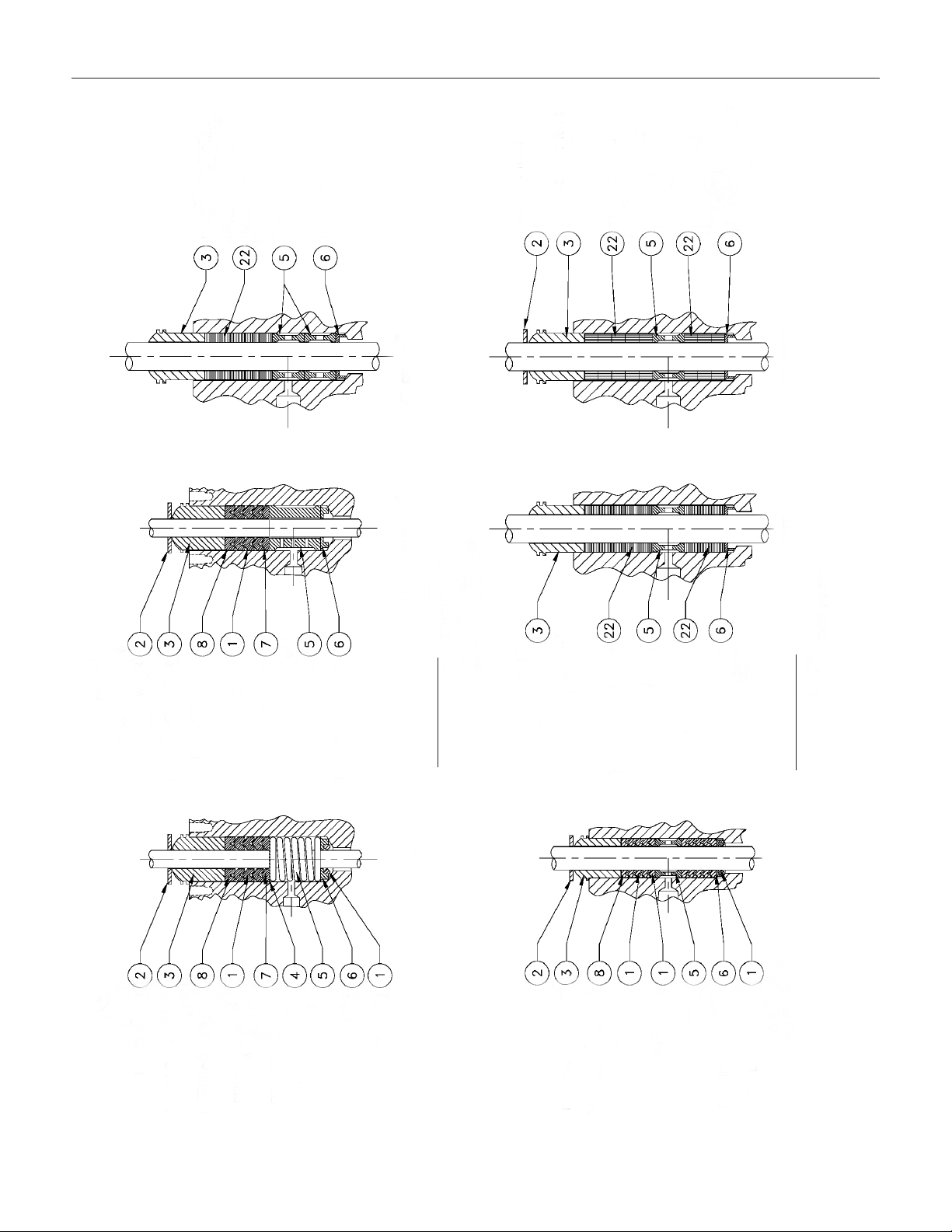
Figure 1: TFE V-Ring Packing Arrangements
All Yoke Sizes
Single Packing
PTFE V-Ring
-5-
Packing Ring
Upper Wiper
Packing Follower
Lantern Ring
Packing Follower
V - Ring
Male Adaptor
Female Adaptor
Packing Ring
Packing Box Ring
Lantern Ring
Packing Box Ring
All Yoke Sizes
Double Packing
PTFE V-Ring
Lower Wiper
Notes:
* Grafoil
is a Registered Trademark for Packings, Seals, Gaskets and other Products of Garlock Garlock Inc.
R
** Garlock
Page 6

Mark EW SEriES GlobE StylE Control ValVES
Replacing Packing Continued,
12. Place the bonnet over the stem and onto the
stud bolts (Figure 4, Key 38) and lubricate with
an appropriate lubricant. If factory lubricated
stud bolt nuts will be used, additional lubrication
is unnecessary. Follow standard bolting
procedures and install the stud bolt nuts (Figure
4, Key 39), ensuring that the body-to-bonnet
joint will withstand test pressures and
application service conditions. Refer to
Table 1 for bolt torque guidelines, unless
accepted bolting procedures demand
otherwise.
13. Refer to Figures 1 and 2 and install new packing
and metal packing box parts. Using a smooth-
edged pipe placed over the pipe stem,
gently tap each soft packing part into the
packing box. Ensure that air is not trapped
between adjacent soft parts.
14. Slide the packing follower, upper wiper and
packing flange (Figure 2, Keys 3, 2 and 20) into
position. Lubricate the packing flange
studs (Figure 2, Key 21) as well as the packing
flange nuts (Figure 2, Key 16), and replace the
packing flange nuts.
15. If using spring-loaded TFE V-Ring packing,
tighten the packing flange nuts using accepted
bolting procedures.
16. Install the actuator onto the valve body assem-
bly and refer to the actuator instruction
manual for directions on reconnecting
the actuator and valve stem.
Trim Removal
Unless otherwise indicated, key numbers in this section
reference Figure 3 for Design EWD and Restricted Trim,
Figure 4 for Mark EWS and Figure 5 for Mark EWT constructions, as well as Class 900 12 x 6-inch construction.
1. Remove the actuator and bonnet, referring to
Steps 1 through 8 in the Replacing Packing
section.
The graphite piston ring(s) (Key 29) in a Mark EWD body
is brittle and in two pieces. Handle with care to avoid
dropping or rough handling of the piston ring(s).
The surface finish of the valve stem (Key 30) is critical for creating a good packing seal. Also,
the inside surface of the cage (Key 26) is important for
smooth valve plug operation and for creating a seal with
the piston ring (Key 29) or seal ring (Key 50). Seating
surfaces of the valve plug (Key 25) and the seat ring
(Key 32) on a metal-seat construction are important for a
tight shutoff. Protect these parts and their surfaces, and
include them in any inspections.
2. If packing parts require replacement, remove
them at this time according to instructions in the
Packing Replacement section of this manual.
Remove the cage adaptor (Key 27)
for any restricted trim body through 8 x 4-inches.
Wrap these parts for protection.
3. Remove the valve plug and stem assembly from
the valve body, setting it on a clean surface. If
the valve plug is being reused, protect the valve
plug seating surface from scratches.
4. Remove the cage (Key 26) and associated gas
kets (Keys 33, 34 and 35). If the cage becomes
stuck in the valve body, tap the exposed
portion of the cage around the circumference,
using a rubber mallet.
5. Remove the following parts:
a. Seat ring (Key 32)
b. Disc seat (Key 44)
c. Seat ring gasket (Key 36)
d. Seat ring adaptor (Key 28)
e. Adaptor gasket (Key 37)
6. The Mark EWS and EWT TFE-seat construction
use a disc (Key 45) placed between the
disc seat and disc retainer (Key 43).
7. Inspect all parts for wear or damage that would
interfere with operation of the control
valve. If replacement or repair of trim parts is
necessary, refer to Lapping Metal Seats or Valve
Plug Maintenance procedures in this manual.
Note: When lifting the valve plug stem (Key 30) and
the attached valve plug (Key 25) from the valve body,
ensure that the cage (Key 26) remains in the body
(Key 24). If the cage were to drop out of the body after
being lifted partially out, cage damage will result.
Use caution to avoid damage to the gasket sealing
surfaces.
-6-
Page 7

Mark EW SEriES GlobE StylE Control ValVES
Lapping Metal Seats
With metal-seat constructions, lapping of the seating
surfaces can improve shutoff. Use a commercial lapping product or a mixture of 600-grit carborundum and
solidified vegetable oil and lap the seating surfaces of
the valve plug and seat ring (Figures 3, 4 and 5, Keys 25
and 32). Deep nicks should be machined out rather than
ground out.
Follow valve assembly procedures until the cage (as well
as cage retainer and bonnet spacer if used) is in place,
and the bonnet is bolted to the body. Create a simple
handle from a piece of strap iron and lock to the valve
body with nuts. Rotate the handle in each direction to
lap the seats. After rotating directions, remove the bonnet and clean the seat surfaces. Completely reassemble
the valve according to directions in the Trim Maintenance section. Test the valve for shutoff and repeat the
procedure if leaking is still excessive.
Valve Plug Maintenance
Key numbers in this section refer to the following Figures
in the manual:
• Figure 3 for Mark EWD Valve Plugs
• Figure 4 for Mark EWS Valve Plugs
• Figure 5 for Mark EWT Valve Plugs
Note: If the piston ring (Key 29) or seal ring (Key
50) are being replaced, protect the surfaces of the
ring groove in the valve plug, or any surfaces of the
replacement ring. Scratches in these surfaces may
prevent proper seal of the replacement ring.
Remove the valve plug (Key 25) according to instructions in the Disassembly section, and proceed as fol-
lows:
Mark EWD – Carbon Filled TFE Piston Ring
a. The piston ring has a split in one place, and if
damage is visible, the ring can be spread
slightly and removed from the groove in the
valve plug.
b. When installing a carbon-filled TFE piston ring,
spread the ring slightly apart at the split. Install it
over the stem and into the valve plug groove.
Ensure the open side faces along the stem,
depending on the flow direction and as shown
in View A, Figure 3.
Mark EWD – Graphite Piston Ring
a. The Mark EWD graphite piston ring is in two
pieces and can be easily removed.
b. The new graphite piston ring is supplied as a
complete ring and must be broken into
two equal portions. Do this by placing the ring
horizontally in a vise and applying pres
sure until the ring snaps. Alternately, place
the ring on the edge of s smooth hard surface
and strike squarely with a hammer.
c. When installing the ring in the valve plug groove,
be sure to match the broken ends of the ring.
Mark EWT Seal Ring – Without Spring Loading
a. This is a closed ring which must be pried or cut
from the groove and therefore cannot be reused.
After the seal ring is removed, the elastomeric
back-up ring can be slightly spread and
removed.
b. When installing a seal ring without spring load
ing, apply lubricant to the back-up ring and the
seal ring (Keys 48 and 51). Install the back-up
ring over the stem (Key 30) and fit into
the groove.
c. Place the seal ring over the top of the valve plug
(Key 25) so it enters the groove on one side of
the valve plug. Gently nudge the seal
ring over the top of the valve plug. Allow time
for the TFE material to cold-flow during
the procedure, so avoid jerking on the ring.
The ring may soom loose when first in the
groove, but will contract shortly after placement
in the cage.
Mark EWT – Spring Loaded Seal Ring
a. When used with valve plugs having a port
diameter of 5-3/8 inches (136.5mm) or less,
the spring loaded seal ring may be removed
without damage by first extracting the retaining
ring (Key 47) with a screwdriver. Slowly slide
the metal back-up ring (Key 51) and seal ring
(Key 48) off of the valve plug (Key 25).
b. When used with valve plugs having a port diam
eter of 7-inches (178 mm) or greater, the spring
loaded seal ring must be pried or cut from its
groove and cannot be reinstalled.
c. The spring loaded seal ring must be placed so
that the open side faces the top or bottom of
the valve plug, according to the flow direction
(Figure 3, View A).
-7-
Page 8

Mark EW SEriES GlobE StylE Control ValVES
Mark EWT – Spring Loaded Seal Ring Continued,
d. To install the seal ring on a valve plug with
5-3/8-inches (136.5 mm) port diameter
or less, first slide the seal ring (Key 48) onto the
valve plug, followed by the metal back-up ring
(Key 51). Then install the retaining ring (Key 47),
inserting one end into the groove, turning the
plug to press the entire ring into the groove.
Use caution so as to avoid scratching the ring
or plug surfaces.
e. For installation of the seal ring onto a valve plug
with a port diameter of 7-inches (178 mm) or
greater, apply lubricant and gently stretch the
seal ring over the top edge of the valve plug.
Allow time for the TFE material to cold-flow during the
procedure, so avoid jerking on the ring. The seal ring
may seem loose when first in the groove, but will contract shortly after placement in the cage.
Note: Do not reuse an old stem or connection stud
with a new valve plug. If this were to be attempted,
a new groove pin hole would need to be drilled into
the stem, which weakens the stem and may cause it
to fail in service. However, a used valve plug may be
reused with a new stem.
f. When replacing the Mark EWD, EWS and EWT
valve stem (Key 30), drive out the groove pin
(Key 31) and unscrew the stem from the
valve plug.
g. Tightly turn in the new valve stem and refer to
Table 5 for the correct drill size. Use the
hole in the valve plug as a guide
and drill through the stem. Remove any
chips or burrs and drive in the new groove pin,
locking the assembly.
4. Install the cage assembly (Key 26). The cage
can be oriented in any rotation with respect to
the valve body.
5. Slide the valve plug (Key 25) and stem assem-
bly into the cage, ensuring that the piston ring or
seal ring (Key 29 or 48) is placed evenly
in the entrance chamber at the top of the cage
(Key 26) or cage retainer (Key 53). This
will avoid damage to the ring.
6. Place the gaskets (Keys 35, 34 or 37 if used,
and 33) and shim (Key 53) on top of the
cage or cage retainer. If there is a cage
adaptor (Key 27) or a bonnet spacer (Key 54)
place an additional flat sheet gasket on
the retainer or spacer.
Note: If reusing the packing, and if it has not been removed from the bonnet, use caution when installing
the bonnet to avoid damage to the packing from the
valve stem threads.
7. Mount the bonnet onto the valve body and
complete assembly procedures according to
Steps 13 through 17 of the Replacing Packing
section. If new packing is not being installed,
omit Steps 14 and 15. Be sure to review
the “Note” prior to step 13.
Parts Ordering
Each Jordan Valve body-bonnet assembly has a serial number which can be found on the valve body. The
same number will appear on the nameplate when the
body assembly is shipped from the Jordan Valve manufacturing facility as part of a control valve assembly.
Refer to this serial number when contacting your Jordan
Valve representative.
Trim Replacement
Key numbers in this section are referenced in Figures as
follows:
• Figure 3 for Mark EWD
• Figure 3 for Restricted Trim Detail
• Figure 5 for Class 900 8 x 6-inch and Mark
EWT constructions
1. With a restricted-trim seat ring construction,
install the adaptor gasket (Key 37) and seat ring
adaptor (Key 28).
2. Install the seat ring gasket (Key 36), seat ring or
liner (Key 32) or disc seat (Key 44).
3. With TFE-seat construction, install the disc and
disc retainer (Keys 43 and 45).
When ordering replacement parts, refer to the part number for each part required, according to the following
parts list.
-8-
Page 9

Mark EW SEriES GlobE StylE Control ValVES
Table 3: Groove Pin Replacement and Valve Stem to Plug Torque
Valve Stem Connection (VSC)
Drill Size,
in mm Ft•Lb N•m
3/4 19.1 3/16 175-250 238-340
1 25.4 1/4 310-355 420-481
1-1/4 31.8 1/4 610-670 830-910
In
Stem Torque
Minimum to Maximum
-9-
Figure 2. Typical Bonnets, shown with single
TFE V-Ring Packing Set
Page 10

Mark EW SEriES GlobE StylE Control ValVES
Parts Reference
Key Description
1 Single TFE V-Ring Packing Set
2 Upper Wiper
3 Packing Follower
4 Special Washer for TFE V-Ring Packing
5 Packing Box Spring / Lantern Ring
6 Packing Box Ring
7 Male Adaptor (Part of Gasket Set)
8 Female Adaptor (Part of Gasket Set)
10 Packing Ring
14 Cap Screw
15 Pipe Plug
16 Packing Flange Nuts
17 Yoke Locknut
18 Bonnet
19 Extension Bonnet Bushing
20 Packing Flange
21 Packing Flange Studs
22 Individual Packing Ring
23 Pipe Plug for Double Tapped Bonnet
24 Valve Body
Key Description
25 Valve Plug
26 Cage
27 Cage Adaptor
28 Seat Ring Adaptor
29 Piston Ring, Design EWD
30 Valve Plug Stem
31 Groove Pin
32 Seat Ring
33 to 37 Gasket Sets
38 Stud Bolt
39 Stud Bolt Nut
40 Pipe Plug
41 Flow Arrow
42 Drive Screw
43 Disc Retainer for TFE Seat
44 Disc Seat for TFE Seat
45 Disc, TFE
48 Seal Ring
51 Back-Up Ring
52 Hex Nut, Stud
-10-
Page 11

Mark EW SEriES GlobE StylE Control ValVES
Figure 3. Mark EWD Series through 12X6
-11-
See View A
Page 12

Mark EW SEriES GlobE StylE Control ValVES
Fig 4. 12x8 Class 900 Bonnet - 5” yoke boss bolting detail
Bonnet Assembly
See Fig. 2
A- See Gasket Sets
Fig 5. Typical 8x6 Valve Body
-12-
Page 13

Mark EW SEriES GlobE StylE Control ValVES
Parts List
Key No. Description Part Number
Single TFE V-Ring Packing Set
1
Includes Female Adaptor, Male
Adaptor, 3 Packing Rings and
Lower Wiper
2 Upper Wiper, Felt
3 Packing Follower, 316 SST
Special Washer, 316 SST
4
For TFE V-Ring Packing
Packing Box Spring, SST
For TFE V-Ring Packing
5
Lantern Ring, 316 SST
6 Packing Box Ring, 316 SST
3/4-inch (19.1 mm) Stem 1R290401012
1-inch (25.4 mm) Stem 1R290601012
1-1/4-inch (31.8 mm) Stem 1R290801012
Upper Wiper, Felt 1J872806332
1-inch (25.4 mm) Stem 1J872906332
1-1/4-inch (31.8 mm) Stem 1J873006332
3/4-inch (19.1 mm) Stem 1E944735072
1-inch (25.4 mm) Stem 1H982335072
1-1/4-inch (31.8 mm) Stem 1H998435072
3/4-inch (19.1 mm) Stem 1F125036042
1-inch (25.4 mm) Stem 1H982236042
1-1/4-inch (31.8 mm) Stem 1H995936042
3/4-inch (19.1 mm) Stem 1F125637012
1-inch (25.4 mm) Stem 1D582937012
1-1/4-inch (31.8 mm) Stem 1D387437012
3/4-inch (19.1 mm) Stem 0N028435072
1-inch (25.4 mm) Stem 0U099735072
1-1/4-inch (31.8 mm) Stem 0W087135072
3/4-inch (19.1 mm) Stem 1J873335072
1-inch (25.4 mm) Stem 1J873435012
1-1/4-inch (31.8 mm) Stem 1J873525012
7 Male Adaptor Included in Gasket Set
8 Female Adaptor Included in Gasket Set
3/4-inch (19.1 mm) Stem (2 req’d) 1D749101052
10 Packing Ring, Graphite
14 Cap Screw, Steel 5-inch Yoke Only, 8 req’d) 1A936224052
15 Pipe Plug, Steel 1/4-inch NPT 1A767524662
16 Packing Flange Nuts, 2 req’d
17 Yoke Locknut, Steel 2-13/16-inch Yoke 1E807423062
18 Bonnet See Following Tables
3/4-inch Stem Style 1 All Sizes 1R351824492
19 Extension
Bonnet
Bushing, Steel
1-inch Stem Style 1 8 x 6 and 12 x 6 1U567624492
1-1/4-inch Stem Style 1 8 x 6 and 12 x 6 1U527824492
1-inch (25.4 mm) Stem (3 req’d) 1D749601052
1-1/4-inch (31.8 mm) Stem (3 req’d) 1D751901052
3/4-inch (19.1 mm) Stem 1E944624112
1-inch (25.4 mm) Stem 1A343324112
1-1/4-inch (31.8 mm) Stem 1A368224112
3-9/16-inch Yoke 1E832723062
Style 2 8 x 6 and 12 x 6 1U763224492
-13-
Page 14

Mark EW SEriES GlobE StylE Control ValVES
Parts List Cont'd,
Key No. Description Part Number
3/4-inch (19.1 mm) Stem 1E944823072
20 Packing Flange, Steel
21 Packing Flange Studs, (2
req’d)
22 Individual Packing Ring
Pipe Plug
23
24 Valve Body See Following Tables
25 Valve Plug See Following Tables
26 Cage See Following Tables
27
28
29 Design EWD Piston Ring See Following Tables
30 Valve Plug Stem See Following Tables
31 Groove Pin
32 Seat Ring See Following Tables
33 to 37 Gasket Sets See Following Tables
38 Stud Bolt, Steel Contact Jordan Valve
39 Stud Bolt Nut, Steel Contact Jordan Valve
40 Pipe Plug for Drain-Tapped
for DoubleTapped
Bonnet
Cage Adaptor for RestrictedCapacity
6 x 4 x 2-1/2-inch Body
Seat Ring Adaptor for
Restricted-Capacity
6 x 4 x 2-1/2-inch Body
316 SST
Body
8 x 6-inch
through
12 x 8-inch
body
Design EWD
or EWT
1-inch (25.4 mm) Stem 0V002425052
1-1/4-inch (31.8 mm) Stem 0W085625052
3/4-inch (19.1 mm) Stem 1E944931032
1-inch (25.4 mm) Stem 0V002531032
1-1/4-inch (31.8 mm) Stem 0W086931032
3/4-inch (19.1 mm) Stem (8 req’d) 1E319101042
TFE
Graphite
Steel for WCB Steel Bonnet 1A369224092
316 SST for 316 SST Bonnet 1A369235072
WCB Steel for WCB Steel Body 1V705722012
410 SST HT for C5 or WC9 Steel Body 1V7057X0012
316 SST for 316 SST Body 1V705733092
WCB Steel for WCB Steel Body 1U239622012
410 SST HT for C5 or WC9 Steel Body 1U2396X0032
316 SST for 316 SST Body 1U239633092
3/4” (19.1 mm) stem diameter 1V326035072
1” (25.4 mm) or 1-1/4 (31.8 mm) stem diameter 1V334035072
3/4” (19.1 mm) stem diameter 1F723635072
1” (25.4 mm) or 1-1/4 (31.8 mm) stem diameter 1D269735072
Steel for WCB Steel Body 1A771528992
316 SST for C5 or WC9 Steel or 316 SST Body 1A771535072
1-inch (25.4 mm) Stem (8 req’d) 1D7518X0012
1-1/4-inch (31.8 mm) Stem (8 req’d) 1D7520X0012
3/4-inch (19.1 mm) Stem (2 req’d) 1D749001052
1-inch (25.4 mm) Stem (2 req’d) 1D751801052
1-1/4-inch (31.8 mm) Stem (2 req’d) 1D752001052
Sales Rep
Sales Rep
-14-
Page 15

Mark EW SEriES GlobE StylE Control ValVES
Parts List Cont'd,
Key No. Description Part Number
41 Flow Arrow, SST 1V106038983
42 Drive Screw, SST (2 req’d) 1A368228982
43 Disc Retainer for TFE-Seat (Design EWS or EWT) Contact Jordan Valve
Sales Rep
44 Disc Seat for TFE-Seat (Design EWS or EWT) Contact Jordan Valve
Sales Rep
45
48
51
Disc, TFE
(-70oF to
400oF)
Seal Ring,
Carbon Filled
TFE
EWT Only
Back-Up
Ring, EWT
only
8 x 6, 12 x 6 1V711906242
10 x 8
12 x 8
8 x 6, 12 x 6 10A2643X012
10 x 8
12 x 8
8 x 6, 12 x 6 1V660005292
Viton
0-400oF
8 x 6, 12 x 6 1V660005392
Ethylene-Propylene
(water or steam)
-40oF to 300oF
52 Hex Nut, Stud 12 x 8 Contact Jordan Valve
Sales Rep
53 Load Ring 8 x 6, 12 x 8 20A3267X012
Key 18 Bonnet, Steel
Body Size,
Inches
8 x 6
12 x 6
12 x 8 5 45A9272X012
Boss Size
Inches
3-9/16 3U509423022
5 2U509822012
Plain Bonnet, Tapped
-15-
Page 16

Mark EW SEriES GlobE StylE Control ValVES
Key 24 Valve Body, Steel
Body Size, Inches
End Connections
8 x 6 12 x 6 12 x 8
RF Flange 300 lb 2V720922012 32A0559X012 45A8259X012
RTJ Flange 2V721122012 32A0565X012 45A8261X012
RF Flange 600 lb 2V721022012 32A0562X012 45A8258X012
RTJ Flange 2V721222012 32A0566X012 458260X012
RF Flange 900 lb 31A8283X012 45A9274X012
RTJ Flange 31A9339X012 45A9275X012
Key 25 Valve Plug
Body
Size In
8 x 6
and
12 x 6
12 x 8 1-1/4 21A21A5283 21A5267X012 21A5358X022 21A5361X012
1. Alloy #6 on valve plug seat and guide
VSC In EWS EWD/EWT
316 SST 316 SST #6
1
316 SST 316 SST #6
3/4 11A5250X012 11A5256X012 1V658435072 21A5351X012
1 11A5251X012 11A5257X012 1V658535072 20A0103X012
1-1/4 11A5252X012 11A5258X012 1V658635072 20A4608X012
1
Key 26 Cage
Body
Material Equal Percentage Quick Opening Linear
Size In
8 x 6
and
12 x 6
17-4PH SST (Hard) 2U505933272 2U506333272 2U506133272
316 SST ENC 2U806748932 2U806948932 2U806848932
316 SST 2U693746102 2U693546102 2U693846102
12 x 8 17-4PH SST (Hard) 20A3245X012 20A2349X012 20A3247X012
316 SST ENC 20A3245X012 20A5469X012 20A5468X012
316 SST 20A4348X012 20A4350X012 20A4349X012
1. For Whisper Cage Contact A Jordan Valve Representative
-16-
Page 17

Mark EW SEriES GlobE StylE Control ValVES
Key 30 Valve Plug Stem (316 SST)
Body
Size In
8 x 6
and
12 x 6
12 x 8 1-1/4 11A3430X622
1. For Type 667 Only
Key 32 Seat Ring
Body Size
In
8 x 6 2V721546172 1V721646062
12 x 6 2V643946172 2V644046062
12 x 8 20A3260X012 20A3260X152
Stem Diameter In Plain Bonnet
Part Number
3/4 1L996435162
1 1N704735162
1K759135162
1-1/4 1K415435162
1K775335162
416 SST 316 SST with Alloy 6 Seat
MKEWIM/0414
1
1
Keys 33-37 Gasket Sets
Body Size
In
-425oF to 450oF 450oF to 800oF Over 800oF -70oF to 400oF
Metal Seat TFE Seat
8 x 6
and
1U5085X0092 1U5085X0062 5085X0072 1U5085X0082
12 x 6
12 x 8 10A3265X012 --- 10A3265X022 10A3265X032
Jordan Valve, a division of Richards Industries
3170 Wasson Road • Cincinnati, OH 45209
513.533.5600 • 800.543.7311 • 513.871.0105 (f)
info@richardsind.com • www.jordanvalve.com
 Loading...