

Page 1

I & M Mark D and DA Series
3170 Wasson Road • Cincinnati, OH 45209
Phone 513.533.5600 • Fax 513.871.0105 (f)
info@richardsind.com • www.jordanvalve.com
Warning: Jordan Valve Control Valves must only be used, installed and repaired in accordance with these Installation & Maintenance Instructions. Observe all applicable public and company codes and regulations. In the event
of leakage or other malfunction, call a qualified service person; continued operation may cause system failure or
a general hazard. Before servicing any valve, disconnect, shut off, or bypass all pressurized fluid. Before disassembling a valve, be sure to release all spring tension.
IntroductIon
Contained in this manual are installation instructions,
maintenance procedures and parts information for the
1-inch and 2-inch Mark D and DA Series Globe and
Angle Style Control Valves. Refer to the appropriate
manuals for instructions for the accompanying actuator and additional accessories.
Trained or experienced personnel should carry out
operation and installation of all pressure equipment.
If you have any questions regarding the equipment,
contact your Jordan Valve representative.
Installation & Maintenance Instructions for the
Mark D & DA Globe and Angle Style Control Valves
3. Unless limited by existing seismic condi tions, the control valve assembly may be
installed in any position. The normal
method is with the actuator vertical above
the valve.
4. Install the valve so the process flow co-
incides with direction shown by the arrow
on the valve body.
5. Use accepted piping and welding
practices when installing the valve in the
line. For flanged valve bodies, use
suitable gaskets between the body
flanges and pipeline flanges.
Note
InstallatIon
Post-welding heat treatment may be required
Warning
Jordan Valve recommends the use of protective
clothing, gloves and eyewear when performing any
installation or maintenance.
Installation of the valve assembly under conditions
which exceed the limits outlined in this manual
or on the nameplate may result in personal injury.
Overpressure may cause sudden release of process pressure or bursting of assembly parts.
The valve conguration and construction materials
of each assembly are specied during ordering to
meet specic pressure, temperature, pressure drop
and controlled uid conditions. Do not operate any
part of the assembly outside of those conditions
without rst contacting Jordan Valve.
1. Before installing the valve, inspect the valve
body cavity for foreign material.
2. Remove all foreign materials such as scale or
welding slag from all pipelines.
on some valve body materials. Avoid damage
to internal elastomeric, plastic and metal parts
by removing all trim. For more information,
contact your Jordan Valve representative.
6. For screwed end connections, apply pipe
compound to pipeline threads.
7. Install a conventional 3-valve bypass
around the body to allow for continuous
operation during maintenance
and inspection.
8. If your actuator and valve body were
shipped separately, refer to the
proper Product Manual for actuator
mounting procedures.
Warning
Packing leakage could result in personal injury.
Valve packing is tightened prior to shipping
but may require readjustment to meet specic
service conditions.
Page 2
Mark D anD Da SerieS Globe anD anGle Style Control ValVeS
MaIntenance
Warning
Personal injury may result from sudden re
lease of any process pressure. Jordan Valve
recommends the use of protective clothing,
gloves and eye wear when performing
any installation or maintenance.
Isolate the valve from the system and relieve
pressure prior to performing maintenance.
Disconnect any operating lines providing air
pressure, control signals or electrical power
to the actuator.
Install bypass valves or completely shut
down the process to isolate the valve
from process pressure. Relieve all pressure
and drain process media from both sides of
valve.
Vent all pressure from the actuator and re
lieve pre-compression from actuator spring.
Depending on the severity of service, valve body
parts experience wear and tear and must be inspected and maintained according to conditions.
This manual includes instructions for lubrication and
maintenance of packing, trim maintenance and lapping of seating surfaces. All maintenance procedures
can be conducted while the valve remains in the line.
Note
If a gasket seal is disturbed while
removing or adjusting gasketed parts,
Jordan Valve recommends installing a new
gasket while reassembling. A proper seal
is required to ensure optimum operation.
Use lock out procedures to ensure the pro
cess remains shut down during maintenance.
Check the packing box for pressurized pro
cess uids even after the valve has been
removed from the pipeline, particularly when
removing packing hardware or packing rings,
or removing packing box pipe plug.
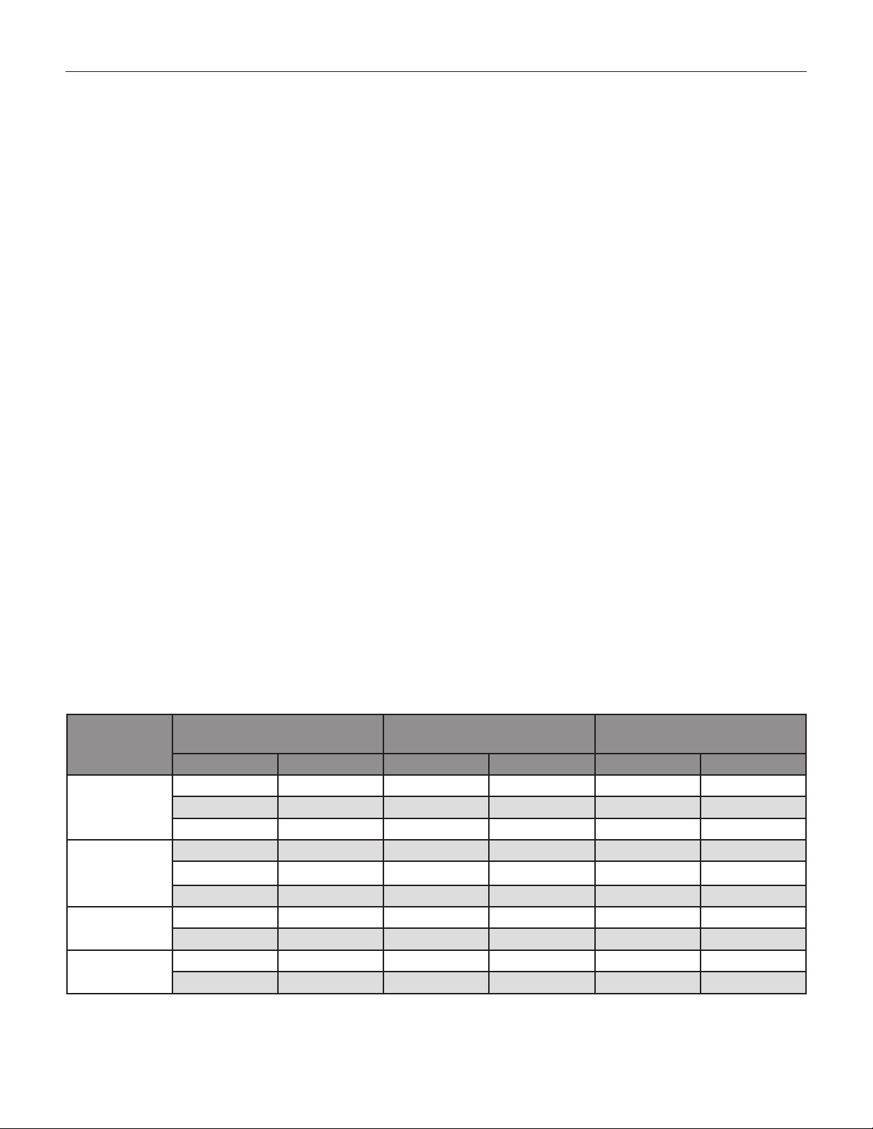
Table 1: Bolting Torque for Packing Box Nuts (Key 2)
Stem Diameter
Valve Rating
3600 or to
Class 1500
6000 or Class
2500
9000 psi 12.7 0.5 6 54 8 264
10,000 psi 12.7 0.5 6 54 8 72
mm in N•m Lbf•in N•m Lbf•in
9.5 0.375 4 36 5 48
12.7 0.5 7 66 11 96
19.1 0.75 16 144 24 216
9.5 0.375 5 42 7 60
12.7 0.5 9 78 12 108
19.1 0.75 20 180 30 264
19.1 0.75 20 180 30 264
19.1 0.75 20 180 30 264
Minimum Recommended
Torque
Maximum Recommended
Torque
-2-
Page 3
Mark D anD Da SerieS Globe anD anGle Style Control ValVeS
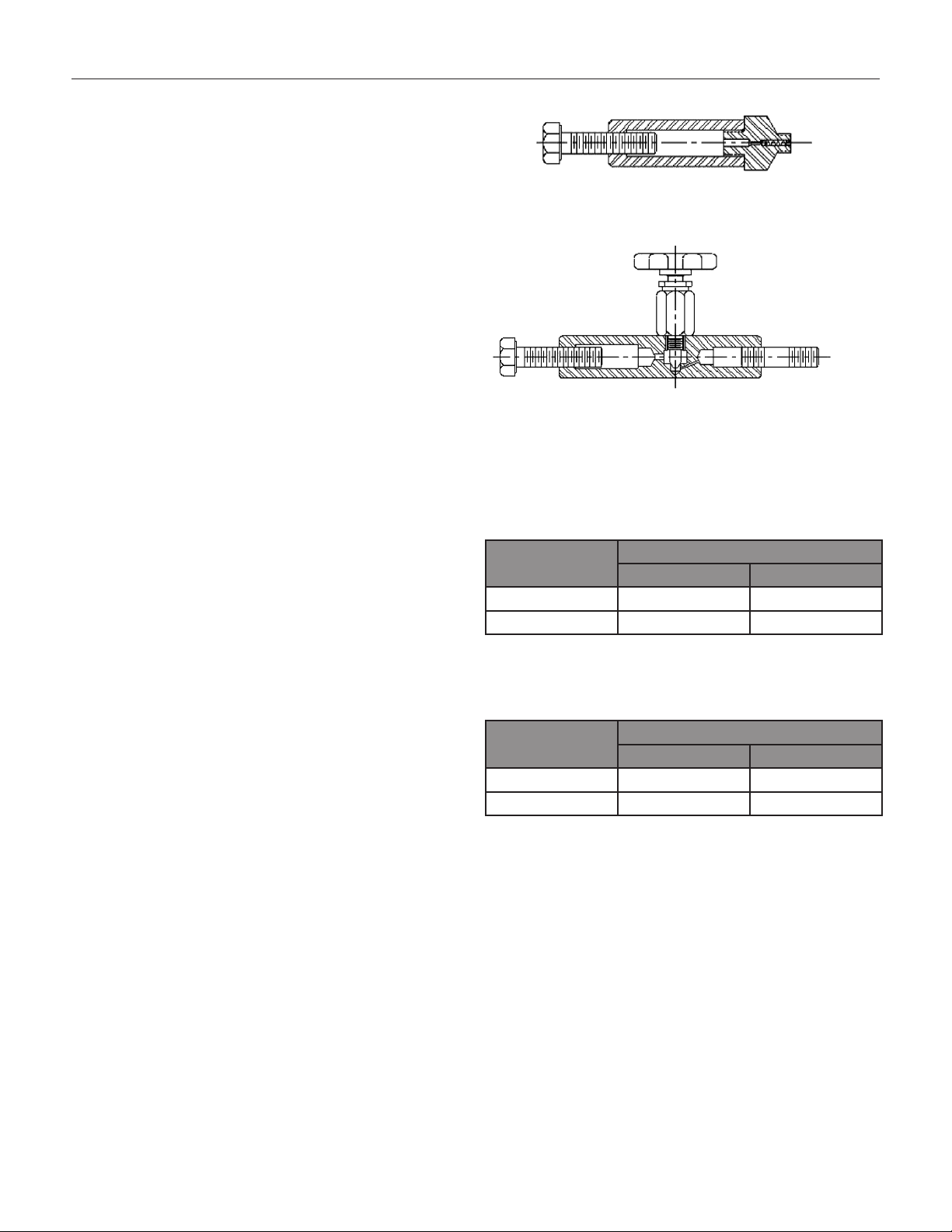
Packing Lubrication
An optional lubricator or lubricator/isolating valve
(Figure 1) may have been installed in place of the pipe
plug within the tapped bonnet. This is used for PTFE/
composition or other packing that require lubrication.
Use a silicon-base lubricant. Packing used in oxygen
service does not require lubrication.
Lubricator - turn the cap screw clockwise to force the
lubricant into the packing box.
Lubricator/isolating valve - open the isolating valve
before turning the cap screw to add lubricant, and
close the isolating valve after lubrication is completed.
Lubricator
Packing Maintenance
Contact your Jordan Valve representative for specific
packing orientation, composition and arrangements.
1. For spring-loaded single PTFE V-ring pack
ing, the spring (Key 16) maintains a sealing
force on the packing. Stop leakage around
the packing follower (Key 11) by tightening
the packing nuts. If the shoulder of the
packing box is touching the top of the bonnet
and leakage cannot be controlled, please
see “Packing Replacement.”
2. If there is packing leakage with other than
spring-loaded packing, try tightening the
packing flange nuts (Key 2) to the minimum
torque value shown in Table 1. Do not exceed
the maximum torque value shown in Table
1. Exceeding the maximum torque value may
cause excessive friction to result.
3. If the packing (Key 13) is relatively new and
tightening the packing flange nuts does not
stop the leakage; a worn or nicked valve stem
or damaged packing box bore might prevent a
proper seal. Follow the steps for Packing
Replacement and inspect the valve stem and
packing box wall during the procedure
Lubricator/Isolating Valve
Figure 1: Optional Lubricator and Lubricator/
Isolating Valve
Table 2: Torque for Bonnet to Body Joint
Valve Size (in.)
1 780 1060
2 1500 2030
Table 3: Torque for Seat Ring (Key 8)
Valve Size (in.)
1 300 407
2 515 698
Recommended Torque
Lbf•ft N•m
Recommended Torque
Lbf•ft N•m
-3-
Page 4

Mark D anD Da SerieS Globe anD anGle Style Control ValVeS
Packing Replacement
Warning
Prior to performing any maintenance
procedures, review the warning notes at the
beginning of the Maintenance section.
1. Isolate the control valve from the line pressure,
release pressure from both sides of the valve
body, and drain the process media from both
sides of the valve.
2. Disconnect any operating lines providing air
pressure, control signals or electrical power
to the actuator. Use lockout procedures to en sure the above measures stay in effect while
you work on the equipment.
3. Disconnect the stem connector, and then re move the actuator from the valve body by un screwing the actuator yoke locknut (Key 4).
4. Loosen the packing flange nuts (Key 2) so the
packing is not tight on the valve stem. Remove
travel indicator parts and stem locknuts from
the valve stem threads.
5. Unscrew the bonnet (Key 6) from the valve
body (Key 7). Carefully lift off the bonnet and
plug/stem assembly (Key 19) as a unit.
11. Inspect the valve stem threads and pack
ing box bore for any sharp edges that might
cut the packing. Scratches or burrs could
cause packing box leakage or damage to new
packing.
12. Install a new bonnet gasket (Key 17), making
sure the gasket seating surfaces are clean
and smooth. Carefully install the plug/stem
assembly into the valve body. Then slide the
bonnet over the stem and thread it tightly into
the valve body, see torque values in Table 3.
13. Use the sequence shown in Figure 2 to install
new packing and associated parts.
14. Slip a smooth-edged pipe over the valve stem,
and gently tap each soft packing part into the
packing box.
15. Slide the packing follower, upper wiper, and
packing flange (Keys 11, 10, and 3) into
position.
16. Lubricate and install the packing flange studs
(Key 1), and nuts.
17. For spring-loaded PTFE V-ring packing, tighten
the packing flange nuts (Key 2) until the
shoulder of the packing follower (Key 11) is
approximately 5/8” above the top of the bonnet.
6. Remove the plug/stem assembly from the bon net. If you plan to re-use the valve plug, pro tect the plug seating surface and the stem
threads to prevent damage.
7. Remove the bonnet gasket (Key 17).
8. Cover the opening in the valve body to protect
the gasket surface and prevent foreign material
from entering into the valve body.
9. Remove the packing flange nuts, packing
flange, upper wiper, and follower (Keys 2, 3,
10, and 11). Carefully push out all the
remaining packing box parts from the bonnet
using a rounded rod or other tool that will not
scratch the packing box wall or bottom guide
bushing.
10. Clean the packing box bore and the metal
packing box parts.
18. For other packing arrangements, tighten the
packing flange nuts (Key 2) alternately
in small equal increments. Continue until one
of the nuts reaches the minimum torque shown
in Table 1. Then tighten the remaining pack
ing flange nut until the packing flange is level
and at a 90-degree angle to the valve stem.
19. Mount the actuator on the bonnet (Key 6) and
connect the actuator and valve plug stem ac cording to the procedure in the appropriate
actuator instruction manual.
20. Check for leakage around the packing follower
when you put the control valve assembly into
service. Retighten the packing flange nuts as
required.
-4-
Page 5

SerieS D Globe anD SerieS Da anGle Style Control ValVeS
Trim Maintenance
Disassembly
1. Remove the actuator and the bonnet as de scribed in steps 1 through 3 of the “Replacing
Packing” procedure.
Warning
The seating surfaces and surface nish of
the seat ring (Key 8), stem (packing seal) and
plug (Key 19) are critical for tight shutoff.
Protect these parts from damage if you plan
to re-use them in the valve.
2. Remove the plug/stem assembly (Key 19) and
the packing parts from the bonnet.
3. If you re-use the valve plug, protect the valve
plug seating surface and the stem threads to
prevent damage.
4. Remove the packing parts as described in the
“Packing Maintenance” procedure.
5. Use a socket wrench to remove the seat ring
(Key 8).
6. Remove the seat ring (Key 8) and seat ring
gasket (Key 9) from the valve body.
7. Inspect parts for damage or wear that would
prevent proper operation of the valve body.
Clean the gasket surfaces.
8. Replace trim parts as necessary or use the
“Lapping Metal Seats” procedure.
Lapping Metal Seats
In any valve body with metal-to-metal seating, a certain
amount of leakage should be expected. However, if
the leakage becomes excessive, lapping can enhance
the condition of the seating surfaces of the plug and
seat ring. Deep nicks in the seating surfaces should be
removed by machining rather than lapping.
There are many lapping compounds available commercially. Be sure to use one of high quality.
Apply the lapping compound to the bottom of the valve
plug. Partially assemble the valve so the seat ring and
valve plug are in place and the bonnet (with bushing
installed) is screwed hand-tight into the body.
Make a simple handle from a piece of metal attached to
the plug stem with nuts. Rotate the handle in opposite
directions with light downward pressure to lap the seat.
Once lapping is complete, remove the bonnet and plug/
stem assembly as a unit, and clean the seating surfaces,
reassemble, and then test for shutoff. If leakage is still
excessive, repeat the lapping process.
Assembly
1. Thoroughly clean the valve body gasket sur-
faces, seat ring and bonnet threads.
2. Apply Never-Seez Nickel lubricant or equivalent
to the threads of the seat ring (Key 8), bonnet
(Key 6), and their mating threads in the body.
3. Put the seat ring gasket (Key 9) into the body.
Screw the seat ring into the body. Use
a socket wrench to tighten the seat ring to the
torque values shown in Table 3.
4. Clean the bonnet gasket-seating surface, and
install a new bonnet gasket (Key 17).
5. If you had not removed the plug/stem assembly
and packing from the bonnet, then install the
bonnet (Key 6) and plug/stem assembly (Key
19) as a unit, into the valve body. To prevent
galling ensure the seating surface of the
plug does not contact the seating surface of the
seat ring. Thread the bonnet tightly into
the valve body; see torque values in Table 2.
6. If you chose to remove the plug/stem assembly
and packing from the bonnet, then remove any
protective covering from the plug/stem
assembly (Key 19) and carefully install it
into the valve body.
7. Slide the bonnet (Key 6) over the stem and
thread it tightly into the valve body.
-5-
Page 6

Mark D anD Da SerieS Globe anD anGle Style Control ValVeS
Assembly Continued,
8. Use the sequence shown in Figure 2 to install
new packing and associated parts.
9. Place a smooth-edged pipe over the valve
stem, and gently tap each soft packing part into
the packing box bore.
10. Slide the packing follower, upper wiper, and
packing flange (Keys 11, 10, and 3) into
position. Lubricate and install the packing
flange studs (Key 1), and packing flange nuts
(Key 2).
11. For spring-loaded PTFE V-ring packing, tighten
the packing flange nuts (Key 2) until the shoul der of the packing follower (Key 11) is approxi mately 5/8” from the top of the bonnet.
For other packing arrangements, tighten the
packing flange nuts (Key 2) alternately in
small equal increments. Continue until one of
the nuts reaches the minimum torque value
shown in Table 1. Then tighten the remaining
packing flange nut until the packing flange is
level and at a 90° angle to the valve stem.
12. Mount the actuator on the bonnet (Key 6),
connect the actuator and plug/stem according
to the procedure in the appropriate actuator
instruction manual.
13. Check for leakage around the packing follower
(Key 11) when you put the control valve
assembly into service. Retighten the packing
flange nuts as required.
Parts Ordering
Each body-bonnet assembly is assigned a serial number, which can be found on the nameplate. Refer to
this serial number when contacting your Jordan Valve
representative.
When ordering replacement parts, specify the serial
number, key number, and part description, from the following Parts Lists.
Upper Wiper
Packing Follower
Female Adaptor
V-Ring
Male Adaptor
Washer
Spring
PTFE V-Ring **Garlock
Upper Wiper
Packing Follower
Female Adaptor
V-Ring
Male Adaptor
Lantern Ring
Packing Follower
Packing Ring
Lantern Ring
R
*Grafoil
R
Single Packing
All Yoke Sizes
Upper Wiper
Packing Follower
Female Adaptor
V-Ring
Male Adaptor
Lantern Ring
PTFE V-Ring
Packing Follower
Packing Ring
Lantern Ring
Packing Ring
Packing Box Ring
*Grafoil
R
PTFE/Composition
Upper Wiper
Packing Follower
Packing Ring
Lantern Ring
Packing Ring
Packing Box Ring
Double Packing
All Yoke Sizes
Notes:
* Grafoil
** GarlockR is a Registered Trademark for Packings, Seals, Gaskets and other Products of Garlock Garlock Inc.
Figure 2: Packing Arrangements
-6-
Page 7

Mark D anD Da SerieS Globe anD anGle Style Control ValVeS
Mark D Series Control Valve Assembly
1
2
3
4
5
6
7
10
11
12
13
14
15
16
8
9
Figure 3: Mark D Series Globe Valve
-7-
17
18
19
Page 8

Mark D anD Da SerieS Globe anD anGle Style Control ValVeS
Mark DA Series Angle Valve Assembly
1
2
3
4
5
6
7
8
10
11
12
13
14
15
16
17
9
Figure 3a: Mark DA Series Angle Valve
-8-
18
19
Page 9

Mark D anD Da SerieS Globe anD anGle Style Control ValVeS
Parts List
Key Quantity Part Name Material Part Number
1 2
2 2
3 1
4 1
5
6 1
7 1
8 1 Seat Ring – see following table Key 8
9 1
10 1
11 1
12 1
13 1
14 3
15 1
16 1
17 1
18 1
19 1 Plug and Stem – see following table Key 19
*M-Flat trim available upon request, contact a Jordan Valve representative for more information.
1
(optional)
Packing Flange Stud Bolt – 2-1/8” Boss Stainless Steel 1E94413103
Packing Flange Stud Bolt – 2-13/16” Boss 1E94443103
Packing Flange Stud Nuts – 2-1/8” Boss Stainless Steel 1E94403103
Packing Flange Stud Bolt – 2-13/16” Boss 1E94453103
Packing Flange – 2-1/8” Boss Steel, CD Plated 1E94372410
Packing Flange – 2-13/16” Boss 1E94422307
Yoke Locknut – 2-1/8” Steel 1E79302306
Yoke Locknut – 2-13/16” 1E80742306
Pipe Plug Stainless Steel 1A76752466
Lubricator or Lubricator / Isolator --- AJ5428000A
Bonnet – 2-1/8” Boss, 1” Body Stainless Steel /
Bonnet – 2-13/16” Boss, 2” Body 2F1342000A
Body – Consult your CVS Controls Representative for valve body, style, size and material
availability
Seat Ring Gasket – 1” Body Mild Steel 1B19862001
Seat Ring Gasket – 2” Body 1B19882001
Felt Wiper – 3/8” Stem Felt 1J1826
Felt Wiper – 1/2” Stem
Packing Follower – 3/8” Stem Steel 1E94393507
Packing Follower – 1/2” Stem 1E94393507
Female Adapter Packing – 3/8” Stem TFE 1F12440101
Female Adapter Packing – 1/2” Stem 1F12430101
Packing – 3/8” Stem TFE 1C7526000A
Packing – 1/2” Stem 1C7527000A
Male Adapter Packing – 3/8” Packing TFE 1F12480101
Male Adapter Packing – 1/2” Packing 1F12470101
Washer – 3/8” Packing Stainless Steel 1F12523604
Washer – 1/2” Packing 1F12433604
Spring – 2-1/8” Boss, 3/8” Stem Stainless Steel 1F12543701
Spring – 2-13/16”, 1/2” Stem 1F12553701
Bonnet Gasket – 2-1/8” Boss, 1” Body Mild Steel 1B19822001
Bonnet Gasket – 2-13/16” Boss, 2” Body 1B19842001
Guide Bushing – 2-1/8” Boss Stainless Steel 1B16913501
Guide Bushing – 2-13/16” Boss 1B16923501
4140 L80
2F1383000A
-9-
Page 10

Mark D anD Da SerieS Globe anD anGle Style Control ValVeS
Key 8 Seat Ring
Body Size
(in)
1
2
Key 19 Valve Plug and Stem
Body
Size
(in)
Orifice Size
mm in
6.4 1/4
6.4 1/4 2 2N71480022 --- ---
1
6.4 1/4 3 2F32800022 2F13880042 1J68940022
9.5 3/8 3 2N73890022 2F31890032 1J68950022
12.7 1/2 3 2N73380022 2F13900032 1J68960022
19.1 3/4 3 2N73930022 2F13910032 1J68970022
6.4 1/4
9.5 3/8 3 27A87920062 2F14280022 1J81910022
2
12.7 1/2 3 2N73330022 2F14290022 1J81930022
19.1 3/4 3 2N62970022 2F14300022 1J81950022
25.4 1 3 2F32690082 2F14310022 1J81970052
31.8 1-1/4 3 --- 2L53310032 1V22340022
Orifice Size (in)
mm in
6.4 1/4 1B50973507 1B50970012 1J6886000A
9.5 3/8 1B50983507 1B50980012 1J6887000A
12.7 1/2 1B50993507 1B50990012 1J6888000A
19.1 3/4 1B51003507 1B51000012 1J6889000A
6.4 1/4 1B51063507 1B51060012 1J6899000A
9.5 3/8 1B51073507 1B51070012 1J8154000A
12.7 1/2 1B51083507 1B51080012 1J8156000A
19.1 3/4 1B51093507 1B51090012 1J8158000A
25.4 1 1B51103507 1B51100012 1J8160000A
31.8 1-1/4 1B58013507 1B58010012 1P7421000A
(in)
Stem
Size
(in)
3/8 2-1/8
1/2 2-13/16
Boss
Size
(in)
MKDandDAIM/0314/2K
316 SST 316 SST with Alloy 6
No.
of
Flutes
1 2N71470032 --- ---
3 2N71400022 2F14270022 1J81890022
Flute
316 SST
CVS Equal %
316 SST with Alloy
Tip
316 SST with
Tungsten Carbide
CVS Equal %
316 SST with
Carbide Tip
Table 4: Weights of Mark D Series Valve Body Assembly
Welded Flange* Short Body
Class
300RF
Class
900/1500RTJ
Class
600RF
ASME
900/1500RF
Jordan Valve, a division of Richards Industries
3170 Wasson Road • Cincinnati, OH 45209
513.533.5600 • 800.543.7311 • 513.871.0105 (f)
info@richardsind.com • www.jordanvalve.com
ASME
300RF
ASME
900/1500RTJ
ASME
300RF
ASME Class
Class
6000
NPT
Class
3600
NPT
Welding
Body size Weight
1" Lbs 27.00 25.00 33.50 34.00 35.00 N/A N/A N/A
Kg 12.25 11.34 15.20 15.42 15.88
2" Lbs 52.50 50.50 50.50 54.00 58.00 62.00 67.00 72.00
Kg 23.81 22.90 22.90 24.49 26.31 28.12 30.39 32.66
* ANSI Standard Flanges only, welded Flanges
Body
size
* ANSI Standard Flanges only, welded Flanges
Weight
1" Lbs N/A N/A 45.00 45.00 N/A N/A N/A
Kg 20.41 20.41
2" Lbs 105.00 103.00 N/A N/A 98.50 99.00 142.00
Kg 47.63 46.72 44.68 44.91 64.41
Class
6000
Class
3600
Welding
Class
150RF
Welded Flange* Short body
Class
900/1500RF
ASME
600RF
2500
 Loading...