

Page 1

I & M Mark CFR Series
3170 Wasson Road • Cincinnati, OH 45209
Phone 513.533.5600 • Fax 513.871.0105 (f)
info@richardsind.com • www.jordanvalve.com
Warning: Jordan Valve Control Valves must only be used, installed and repaired in accordance with these Installation & Maintenance Instructions. Observe all applicable public and company codes and regulations. In the event
of leakage or other malfunction, call a qualified service person; continued operation may cause system failure or
a general hazard. Before servicing any valve, disconnect, shut off, or bypass all pressurized fluid. Before disassembling a valve, be sure to release all spring tension.
IntroductIon
These Installation Instructions provide installation and
Start Up procedures for the Mark CFR Regulator.
InstallatIon
It is recommended that only qualified or authorized
personnel install and maintain the Mark CFR regulator.
Prior to installing, make sure there is no damage to
the regulator, as well as foreign debris in all tubing or
piping connections to the installation.
Ensure proper safety procedures are adhered to
during installation and maintenance.
Warning:
Do not install any pressure equipment where
service conditions exceed the manufacturer’s
specications. Over pressuring of regulator may
result in leakage, equipment damage or injury.
Excessive pressure can cause the pressure
containing parts to burst, or accumulated gas to
explode. The Mark CFR Filter Regulator should not
be used with hazardous gas unless vented to a safe
area.
The Mark CFR regulators internal relief valve does
not provide overpressure protection. The internal
relief valve is designed for minor seat leakage only.
Additional overpressure protection may be required
should the inlet pressure exceed the maximum
pressure rating of the downstream equipment, or
maximum allowable outlet.
Periodically inspect the regulator for damage, and
after an overpressure condition. Remove from service
and replace or maintain the regulator as required.
1. Install the regulator so that the direction of flow
is from the IN to the OUT, as marked on the
regulators housing.
Installation & Maintenance Instructions for the
Mark CFR Series Supply Regulators
2. For best drainage, install the regulator so that
the drain valve (12) is at the lowest possible
point.
3. Prevent plugging of the spring case vent and
keep the spring case from collecting moisture,
corrosive chemicals or other materials
by orienting the vent to the lowest possible point
on the spring case. For panel mounted vented
installations, the 1/4" NPT spring case vent may
be remotely vented by installing tubing
or piping.
4. To change the filter/drain orientation, rotate the
filter cap with regards to the regulator body.
Change the spring case/vent orientation
by rotating the spring case in relation to
the regulator body.
Warning
Never adjust the control spring to produce pressure beyond its highest outlet pressure range. Over
pressuring the spring can cause bursting of pressure containing parts, or explosion of accumulated
gas. If the range of the control spring does not reach
the desired outlet pressure install a spring with the
proper range according to the maintenance section.
5. Suitable means of venting the regulator inlet
and outlet pressures for regulator
shutdown may be achieved by installing
upstream block and vent valves
and downstream block and vent
valves if required.
6. Apply pipe compound or suitable Teflon tape to
the male pipe threads prior to making connec
tions, take care not to get excess pipe
compound inside piping or regulator.
7. Install 1/4" NPT supply tubing or pipe fitting to
the inlet of the regulator body marked
“IN”. Proceed to install 1/4” tubing or pipe fitting
to the other side of the regulator body marked
“OUT”.
8. The additional 1/4" NPT outlet may be used for
an optional Jordan Valve pressure gauge. If a
gauge is not being utilized, a 1/4" NPT
plug must be used.
Page 2
Mark CFr SerieS PreSSure reduCing SuPPly regulatorS
InstallatIon contInued,
9. Should the Mark CFR regulator be installed
in an existing installation, it may be nec-
essary to install spacers on the mounting bolts
to adapt to the installation. If mounting
bolts are too long place a spacer on
the mounting bolt and ensure at
least two full threads of engagement.
startup and adjustment
1. Once installation is complete and downstream
equipment is properly adjusted, slowly open the
supply and downstream shutoff
valves (if installed) while using pressure gauges
to monitor supply and outlet pressure.
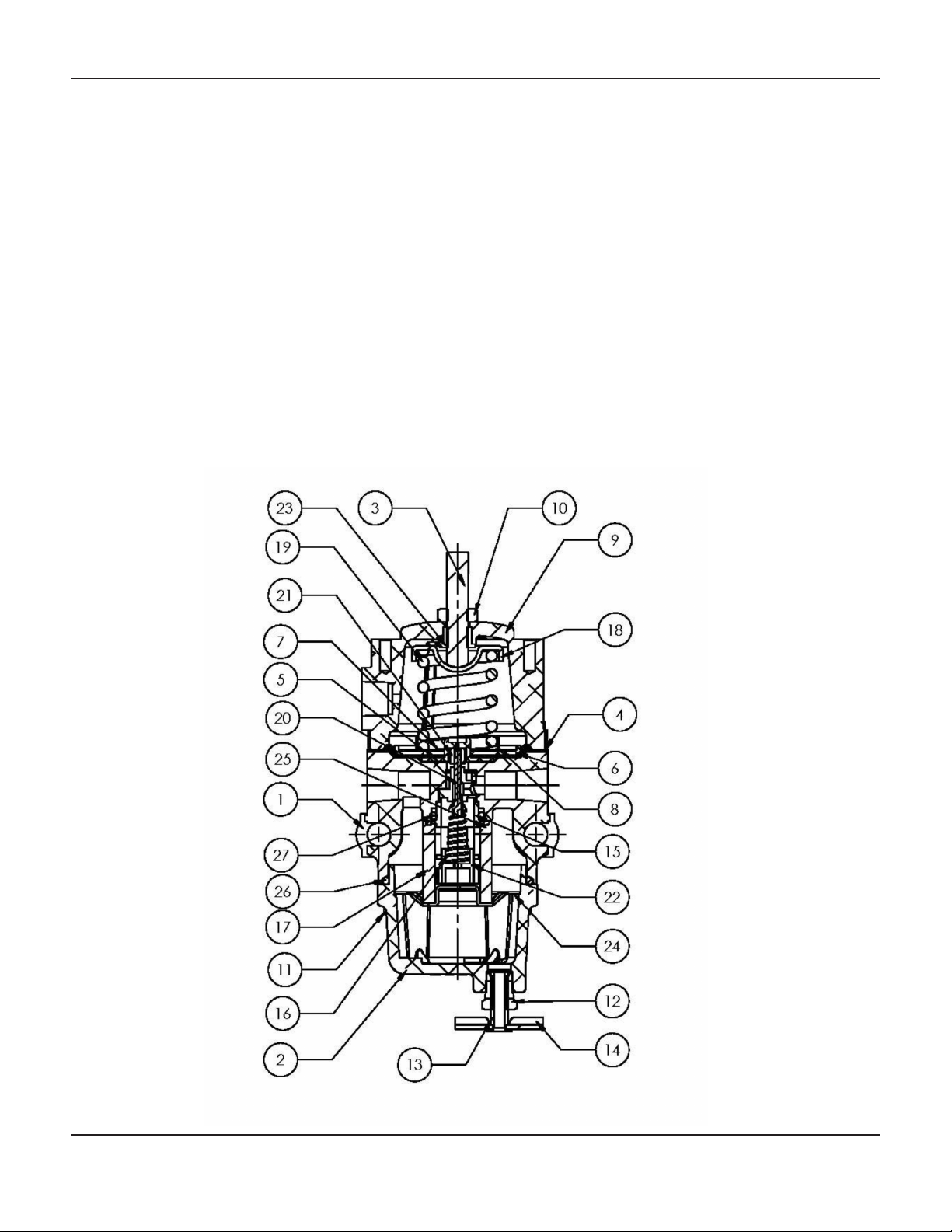
mark cFr assembly
2. Should outlet pressure adjustment be required,
install and monitor outlet pressure using
a gauge during the start-up procedure.
The Mark CFR regulator outlet pressure can
be raised or lowered by loosening the locknut
(10), and turning the adjustment screw (3),
clockwise to increase outlet pressure, or counter
clockwise to decrease outlet pressure.
3. Tighten the locknut (10) one the desired outlet
pressure has been properly set as required.
4. Periodically inspect the regulator for signs or
wear or damage, and repair or replace
as necessary.
For more information or questions, please contact a
Jordan Valve Representative.
-2-
Page 3

MKCFRIM/0214/2K
Mark CFr SerieS PreSSure reduCing SuPPly regulatorS
mark cFr parts lIstIng
Item Description Part Number Qty
1 Body, Aluminum T40643T0RG2 1
2 Dripwell, Aluminum T21040T0012 1
3 Adjusting Screw T14061T0012 1
4* Diaphragm
5 Push Post T14119T0012-2 1
6* Diaphragm Plate
7* Diaphragm Ret. Ring
8 Lower Spring Seat T14119T0012-5 1
Spring Case – 1/4" NPT Vent T14070T0042 1
9
Spring Case – Vent to atmosphere (drilled) T140707T0012 1
10 Lock Nut 1A946324122 1
11 Flange Screw 1B784028982 10
12 Drain Valve Body 1K418918992-1 1
13 Drain Valve Plug 1K418918992-2 1
14 Drain Valve Handle 1D5604000A2-3 1
15 Valve Cartridge Body T80434T0012 1
16 Valve Spring T14105T0012 1
17* Filter Element GE32761X012 1
18 Upper Spring Seat T14051T0012 1
Spring – 0 to 35 psig T14059T0012 1
19
Spring – 0 to 60 psig T14058T0012 1
Spring – 0 to 125 psig T14060T0012 1
20* Valve Plug T14053T0042 1
21* Soft Seat T14055T0012 1
22 Valve Retainer T14071T0012 1
23 Spring Case Insert T14070T0052 1
24 Filter Retainer T14052T0012 1
25 Filter Gasket T14081T0012 1
26 O-Ring T14380T0012 1
27 O-Ring T14380T0012 1
(1)
Items 4, 6 and 7 are included in Diaphragm Assembly
*Included in Mark CFR Repair Kit CFR-RK 1
(1)
(1)
(1)
T14119T0012-1 1
T14119T0012-3 1
T14119T0012-4 1
T14119T0022 Nitrile (no relief) 1
T14119T0012 Nitrile (with relief) 1
Jordan Valve, a division of Richards Industries
3170 Wasson Road • Cincinnati, OH 45209
513.533.5600 • 800.543.7311 • 513.871.0105 (f)
info@richardsind.com • www.jordanvalve.com
 Loading...