

Page 1
I & M Mark 82
3170 Wasson Road • Cincinnati, OH 45209 USA
Phone 513-533-5600 • Fax 513-871-0105
info@richardsind.com • www.jordanvalve.com
Installation & Maintenance Instructions for
Mark 82 Temperature Regulators
Warning: Jordan Valve Temperature Regulators must only be used, installed and repaired in accordance with these
Installation & Maintenance Instructions. Observe all applicable public and company codes and regulations. In the event
of leakage or other malfunction, call a qualifi ed service person; continued operation may cause system failure or a
general hazard. Before servicing any valve, disconnect, shut off, or bypass all pressurized fl uid. Before disassembling a
valve, be sure to release all spring tension.
Please read these instructions carefully!
regulator.
The fl ow arrow on the regulator body must be point-6.
Your Jordan Valve product will provide you with long-term,
trouble-free service if it is correctly installed. Spending a
few minutes of your time reading these instructions now
may save hours of trouble and downtime later.
ed in the direction of the fl ow. The regulator may be
installed vertically or horizontally without affecting its
operation.
For best control, 3’ 0” straight sections of pipe should 7.
be installed on either side of the regulator.
Upstream and downstream piping near the regulator 8.
should be insulated to minimize condensation in hot
vapor lines.
For injection heating applications, the regulator 9.
should be installed above the maximum water level
in the tank, or a check valve should be installed to
prevent water from backing up into the regulator.
For best regulation, the temperature regulator 10.
should be installed as closely as possible to the unit
in which the temperature is being controlled.
On steam control applications, install a steam trap 11 .
of suffi cient capacity to drain the coil or condenser.
Be sure to have a good fall to the trap, and no back
pressure. Best control is obtained when the coil or
condenser is kept dry.
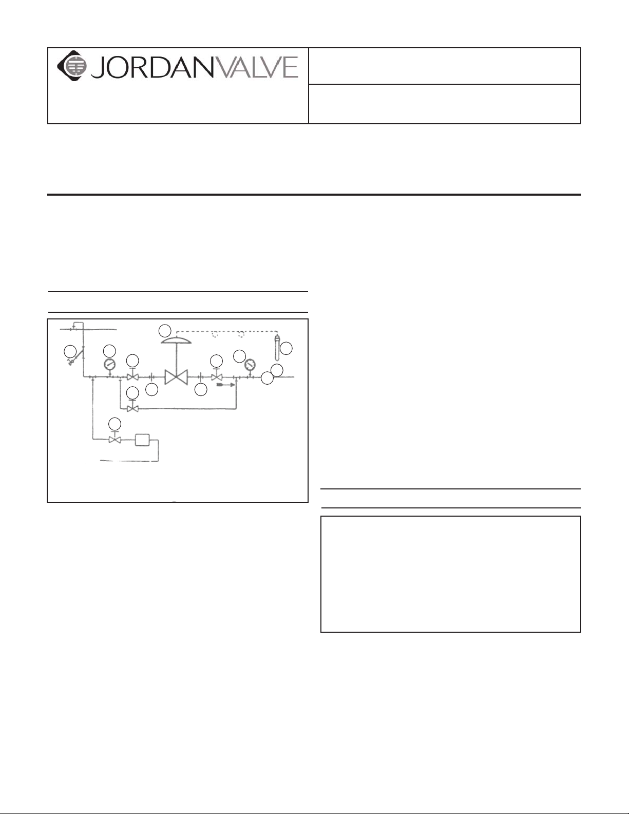
Main Steam Line
3
Installation
4
1
1
Steam
1
Trap
Condensate
Return Line
5
2 2
By-Pass Line
1. Shut-Off Valve
2. Pipe Union
3. Strainer & Drain Valve
4. Pressure Gauge
5. Jordan Regulator
6. Relief Valve
7. Thermal Bulb
4
1
7
6
R
Bulb Installation
To protect the temperature regulator from grit, scale, 1.
thread chips, and other foreign matter, all pipe lines
and piping components should be blown out and
thoroughly cleaned before the temperature regulator is installed.
Shutoff valves, pressure gauges, and bypass piping 2.
should be installed as indicated in the diagram to
provide easier adjustment, operation and testing.
In preparing threaded pipe connections, care should 3.
be taken to prevent pipe sealing compound from
getting into the pipe lines. Pipe sealing compound
should be used sparingly, leaving the two lead
threads clean.
A line strainer should be installed on the inlet side 4.
of the temperature regulator to protect it from grit,
scale and other foreign matter. A 0.033 perforated
screen is usually suitable. Line strainers are available from Jordan Valve.
Install the regulator in the highest horizontal line of 5.
piping to provide drainage for inlet and outlet piping, to prevent water hammer, and to obtain faster
The Thermal System is a hermetically sealed unit
consisting of a sensing bulb, capillary tubing, pro-
tective armor, and actuator assembly. This unit
contains the thermostatic charge that operates
the temperature regulator. Please do not tamper
with it. In case the charge is lost, the thermal
system must be replaced as a complete unit. It is
not repairable in the fi eld and must be returned
to the factory for repairs.
Correct Installation – For effective temperature con-1.
trol, correct installation of the sensing bulb is essen-
tial. For best results, the bulb should be installed
at a point of true representative temperature and
where there is good circulation. A thermometer or
other temperature sensing device (if used) should
be placed as close as possible to the sensing bulb
of the regulator.
Handle the capillary and armor carefully so they are 2.
not crushed, kinked or twisted. A bend of 4½” ra-
Page 2

dius or larger is recommended.
Horizontal Mounting3. – When the bulb is to be
mounted horizontally, it must be turned so that the
word TOP (stamped on the adaptor) faces upward.
Vertical Mounting4. – No special precaution is re-
quired when the bulb is mounted vertically pointing
down.
Inverted Mounting5. – A special capillary is required
if the tip of the bulb will be higher than the capillary end. The temperature regulator equipped with
a standard capillary will not function properly in an
inverted position.
Insertion6. – For accurate control, the entire length of
the bulb should be inserted. Avoid locating a bulb
in the direct path of steam or water. Never lay a bulb
on the bottom of the tank. Approximately 8” is suffi cient distance from the source of heat or coolant
to the sensing bulb.
Pipeline Mounting7. – When installing a sensing bulb
in piping, be sure that the pipeline is at least twice
the diameter of the sensing bulb so that free fl ow is
obtained around the bulb.
Finned Bulbs8. – Finned bulbs should be installed at
right angles to the air movement. Good circulation
is required to sense the average temperatures.
When the bulb is installed at a point higher than the 9.
regulator itself, the range may be somewhat lowered. Conversely, the range may be raised if the
bulb is installed below the regulator.
Trouble Shooting
If You Experience Erratic Control:
An oversized valve causes cycling or hunting. An
undersized valve causes temperature to drop under
peak loads. Recalculate required size from Jordan
Catalog TCV.
Inlet pressure may be low.
Steam traps downstream my need reconditioning.
Foreign matter may be lodged in valve seats.
Valve stroke may be out of adjustment.
If You Experience Underheating:
Be sure the by-pass seats are fully open.
Be sue the inlet pressure is adequate.
Clean line strainer screens.
Clean steam traps and be sure they are working
properly. If the return line from the trap is cool, the
steam coil may be clogged.
If You Experience Overheating:
Overheating is often caused by foreign matter hold-
ing the valve seats in the open position. Inspect and
clean seats or replace them.
Check stroke adjustment.
Check for damage or failure of the thermal system.
If You Experience Undercooling or Overcooling:
Be sure the coolant is circulating properly and that
all steps have been taken as indicated for underheating or overheating in the steps above.
If You Experience Thermal System Failure:
Thermal system failure is usually indicated by failure of the
regulator to respond to temperature changes, and when
all other trouble shooting steps have failed to correct the
problem. The adjusting spring will hold a direct acting
valve OPEN or reverse acting valve CLOSED.
The thermal system can be tested by placing the sensing bulb in a container which can be quickly heated with
steam or hot water, or cooled with cold water or crushed
ice. Observe the valve stem while alternately heating and
cooling the bulb. If the stem does not move, it is likely that
the thermal system has lost its fi ll. The thermal system is
hermetically sealed and cannot be repaired in the fi eld. It
must be replaced by a complete, new thermal system or
the old unit must be repaired at the factory.
Start Up
Close the inlet and outlet shut-off valves.1.
Slowly open the by-pass, and begin heating or cool-2.
ing action.
Fully open the inlet shut-off valve. Then slowly open 3.
the outlet shut-off valve.
Close the by-pass valves when the approximate 4.
temperature is reached.
Allow approximately 30 minutes to reach stable op-5.
eration before attempting to adjust the temperature
setting (and after each new setting).
To change the control temperature, rotate the ad-6.
justing wheel downward to decrease and upward to
increase the temperature setting.
Note: These instructions apply to both the direct acting
and the reverse acting regulators. The reverse acting regulator is identical to the direct acting regulator except for
the design and operation of the pilot valve.
In the direct acting regulator, an increase of tem-7.
perature at the sensing bulb will close the pilot valve
seats which causes the main valve seats to close.
In the reverse acting regulator, an increase of tem-8.
perature at the sensing bulb will open the pilot valve
seats and main valve seats.
Therefore the reverse acting pilot valve assembly is an
inverted version of the direct acting pilot valve. However,
because of design differences, the upper bonnet of the
regulator must be replaced to change the valve action.
-2-
Page 3

Valve Seats
A. Disassembly
The valve seats of all Jordan regulators are
lapped to a light band fl atness. Maintaining such
tolerances is of great importance for your assurance of excellent control and tight shut-off. Do
not use metallic objects in removing the seats.
Care in handling is important. Improper handling
will result in leakage or improper control upon
installation.
Close shut-off valve on each side of the regulator.1.
Remove the control valve from the line.2.
Note the scribe line on the side of the valve body 3.
and cap. Secure the outlet body hex (6) in a vise.
Remove inlet pilot tube (25). Remove the cap screws
(28) and lift the cap (7) straight up. Please note that
there is an index pin secured in the valve cap that
fi ts into the index pin hole in the valve plate (2). This
index ping is on the same side as the scribe line on
the valve cap and body, and it positions the valve
plate in the valve body.
Before removing, check the valve disc (1) for a 4.
stamped arrow. This arrow points to the scribed
line and the index pin hole in the valve plate. Since
the disc can be rotated 180° in some sizes without
affecting stroke adjustment, there may be no arrow
on the valve disc. Remove the valve disc and place
on bench with the lapped surface up.
A light tapping on the valve body is normally suf-5.
fi cient to loosen the pressure rings (8). Invert the
valve body while holding the pressure ring and plate
in place; then slowly let them drop out of the body
into your hand.
Clean all the parts of the body and cap with solvent. 6.
The valve disc and plate then may be cleaned. Place
a piece of 4/0 polishing paper or jeweler’s cloth on a
smooth, fl at surface such as a surface plate and polish the lapped seating surfaces using a fi gure eight
motion. If the parts are scarred, do not attempt to
re-lap them, but return them to the factory for repair
or replacement. If the seats are not scarred deeply,
they can be repaired many times at nominal cost.
The vertical milled sections of the valve cap serve as 7.
a guide for the disc while stroking. A 0.005 feeler
gauge should be used to check the clearance between the valve disc and the disc guides. To do so,
place the valve disc in the cap with the lapped surfaces facing upward and check this clearance. If the
clearance is less than 0.005, clean the disc guides
with a smooth fi le.
B. Reassembly
Replace the valve plate. In replacing, make certain 1.
that the index pin hole is on the same side as the
scribe line on the valve body. Align the disc pin so
that it is centered in the body bore and protrudes
upward through the slot in the plate.
In replacing the valve disc, the stamped arrow 2.
should be pointing to the scribe line on the valve
body. Place the valve disc on the valve plate, engaging the disc pin.
If necessary, heat (or cool) the sensing bulb to open 3.
the pilot valve.
To check the stroke adjustment, blow air into the 4.
inlet pilot connection. The main valve will stroke to
the open position, and the orifi ces should be open
and in perfect alignment. If they are not, an adjustment is required.
To obtain the proper adjustment, remove the valve 5.
plate and disc from the valve body and loosen the
stem locknut (18). Adjustment is obtained by rotating the disc pin (4) on the valve stem.
When this preliminary adjustment is obtained, lock 6.
the valve stem locknut while holding the disc pin
with an open end wrench.
Now rotate the disc pin so that the valve plate and 7.
disc can be positioned in the valve body.
Insert the valve plate and disc in the body bore, us-8.
ing the same precautions as outlined above.
The seats will be in the closed position. To check 9.
the adjustment again, blow air into the inlet pilot
connection to open the valve. Check the alignment
of the orifi ces.
If orifi ces do not line up properly, further adjustment 10.
will be required.
Place the plate and disc into the body bore followed 11 .
by the pressure ring (8).
Note that the pressure ring (8) has one lapped sur-12.
face. In replacing the pressure ring, make certain
that the lapped surface faces the valve plate.
In replacing the valve cap (7), note that the scribe 13.
line on the valve cap and the valve body must be in
alignment. Use care to make certain the disc guides
and the index pin are properly aligned with the valve
disc and the index pin hole in the valve plate. Normally, a slight rotation of the valve cap is suffi cient to
obtain proper alignment.
Replace the cap screws and tighten uniformly, being 14.
careful not to torque excessively.
Replace inlet pilot tube (25).15.
Thermal System
The thermal system is a hermetically sealed unit 1.
consisting of a sensing bulb, capillary tubing, protective armor, and actuator assembly. This unit contains the thermostatic charge that operates the TCV.
Please do not tamper with it. In case the charge is
lost, the thermal system must be replaced as a complete unit. It is not repairable in the fi eld and must
be replaced or returned to the factory for repairs.
The thermal system is easily removed in the fi eld 2.
-3-
Page 4

by releasing the spring compression (by rotating the
adjusting wheel downwards) and removing the four
fi llister head actuator screws (39).
Lift out the upper spring guide (41) and pilot stem 3.
(33). If necessary to replace pilot stem, remove the
upper locknut (40) and unscrew the upper spring
guide. Count the number of turns required to remove the upper spring guide. Replace the upper
spring guide on the new pilot stem, using the same
number of turns that were used to remove it. Lock it
in position, using the upper locknut (40).
After removing the upper spring guide assembly, the 4.
adjusting spring (31) may be removed. Replace if
necessary and replace the upper spring guide assembly.
Place the thermal system onto the cage (11) and 5.
reinsert the four actuator screws. The valve stroke
adjustment will not be affected if these steps are
carefully followed.
Replacement of Stem Packing
Turn adjusting wheel (35) until all spring compres-1.
sion is removed.
Completely unthread the ring nut (23).2.
Lift off entire top assembly, being careful to avoid 3.
the trapped steam which will now escape. Examine
the pilot stem (33) for dirt.
Remove packing nut (13) and packing gland (14).4.
Remove pilot seat (12) and examine the Tefl on ring 5.
for foreign matter which might prevent the pilot stem
from seating properly.
In the direct acting regulator, the lower end of the pi-6.
lot stem is the seating surface. In the reverse acting
regulator, the lower pilot stem is separate from the
pilot stem and is removed after the pilot seat.
Replace packing (15) and o-ring (16).7.
Reassembly in reverse order.8.
Replacement of Main Valve Diaphragm
Remove the inlet pilot tube (25) and outlet pilot tube 1.
(26). Follow the procedure outlined under Valve
Seats and remove the valve disc and plate.
Unscrew the bottom cap (20) and remove the lower 2.
spring (22) and lower spring guide (21).
Remove the bonnet screws (29) and lift the bonnet 3.
assembly from the main valve body (6).
The diaphragm (30) can now be removed and re-4.
placed if necessary.
Remove the diaphragm plate (32).5.
To remove the disc pin (4), unscrew the stem lock-6.
nut (18) and the disc pin from the valve stem (5).
The stem can now be removed upward through the
body fl ange.
The disc pin is removed through the valve body 7.
base.
Reassemble in reverse order. Insert the stem 8.
through the body fl ange and disc pin into the body
bore.
Thread the stem into the locknut and then into the 9.
disc pin approximately ¼”.
Place the main diaphragm plate (32) on the valve 10.
stem.
Replace the main diaphragm, making sure that it is 11 .
installed properly in the recess of the valve body.
Place the valve bonnet assembly on the valve body 12.
and tighten cap screws uniformly to approximately
120 inch/pounds torque.
Insert the return spring guide (21) and the return 13.
spring (22) in the bottom cap (20) making certain
that the spring guide engages the disc pin properly.
A stroke adjustment will be required. Please not the 14.
procedure outlined under Valve Seats, Reassembly.
Replace the inlet pilot tube and outlet pilot tubes.15.
Thermometer
If the regulator is equipped with a dial thermometer, it can
be re-calibrated by holding the pointer hub with a screwdriver and moving the pointer to the correct temperature.
Torque
Torque Requirements for Body Bolts
Valve Size Torque (in./lbs.)
1/4” & 3/8” 70
1/2” & 3/4” 110
1” & 1-1/4” 120
1-1/2” 140
2” 140
Ordering Spare Parts
Use only genuine Jordan Valve parts to keep your valve
in good working order. So we can supply the parts, which
were designed for your valve, we must know exactly which
product you are using. The only guarantee to getting the
correct replacement parts is to provide your Jordan Representative with the valve serial number. This number is
located on the valve identifi cation tag. If the serial number
is not available, the parts needed for your valve might be
determined using the following information: Model number, Valve Body size, Plug Material and Seat Size, Spring
Range or Set Point, Trim Material, Part Name - Number
and Quantity (see parts list chart).
Note: Without a valve serial number, any parts ordered
incorrectly are subject to a minimum 25% restock charge
when returned.
-4-
Page 5

Illustration and Parts List
51
25
7
1
8
28
42
31
38
37
34
12
23
16
12.1
45
40-48
46
33
47
44
43
39
41
11
35
13
14
15
17
12. 2
10
29
26
30
32
5
18
4
2
6
21
22
20
Item Description Item Description Item Description
1 Disc 16 O-Ring 34 Nut
2 Plate 17 Pipe Plug 35 Adjusting Wheel
4 Disc Pin 18 Nut 37 Washer
5 Stem 20 Bottom Cap 38 Adjusting Screw
6 Body 21 Spring Guide 39 Screw
7 Cap 22 Lower Spring 40 Nut
8 Pressure Ring 23 Ring Nut 41 Spring Guide
10 Bonnet 25 Inlet Pilot Tube 42 Screw
11 Cage 26 Outlet Pilot Tube 43 Diaphragm Case
12 Pilot Seat 28 Body Cap Screw 44 Diaphragm Dome
12.1* Pilot Stem 29 Bonnet Cap Screw 45 Diaphragm Plate
12.2* Pilot Stem Spring 30 Diaphragm 46 Diaphragm
13 Packing Nut 31 Adjusting Spring 47 Gasket
14 Packing Gland 32 Diaphragm Plate 48 Lock Washer
15 Packing 33 Stem † Recommended Spare Parts
* Parts required for reverse acting regulators only.
Bulletin IM-MK82-1010
3170 Wasson Road • Cincinnati, OH 45209 USA
Phone 513-533-5600 • Fax 513-871-0105
info@richardsind.com • www.jordanvalve.com
 Loading...