

Page 1
I & M MK 801/802 Series
3170 Wasson Road • Cincinnati, OH 45209 USA
Phone 513-533-5600 • Fax 513-871-0105
info@richardsind.com • www.jordanvalve.com
Warning: Jordan Valve temperature regulators must only be used, installed and repaired in accordance with these
Installation & Maintenance Instructions. Observe all applicable public and company codes and regulations. In the
event of leakage or other malfunction, call a qualied service person; continued operation may cause system failure
or a general hazard. Before servicing any valve, disconnect, shut off, or bypass all pressurized uid. Before disassembling a valve, be sure to release all spring tension.
Please read these instructions carefully!
Your Jordan Valve product will provide you with long,
trouble-free service if it is correctly installed and maintained. Spending a few minutes now reading these instructions can save hours of trouble and downtime later.
When making repairs, use only genuine Jordan Valve
parts, available for immediate shipment from the factory.
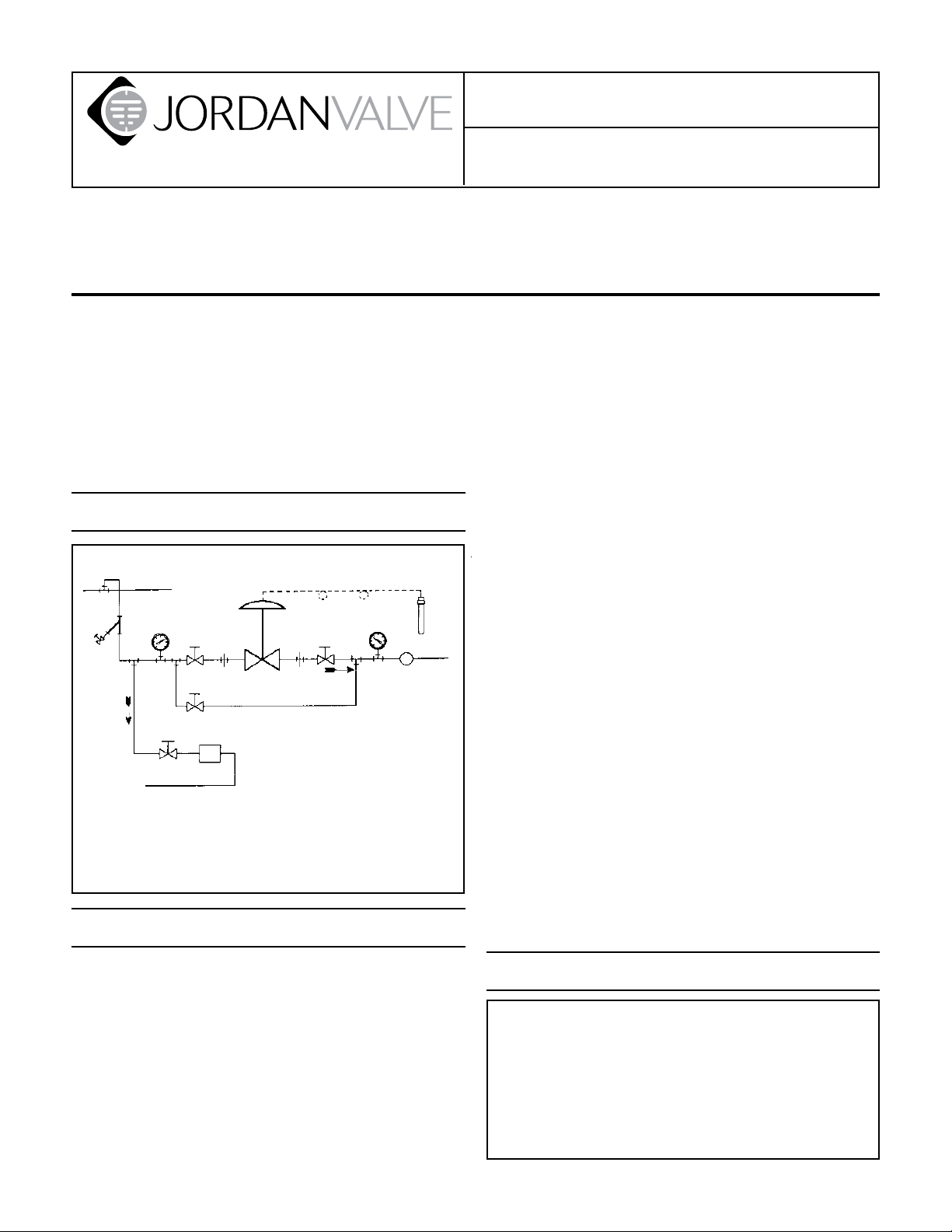
Ideal Installation
3
Main Steam
Line
4
1
1
1
Condensate
Return Line
Steam
Trap
5
2
By-Pass Line
1 Shut-off Valve
2 Pipe Union
3 Strainer & Drain Valve
4 Pressure Gauge
5 Jordan Valve Regulator
6 Relief Valve
7 Thermal Bulb
Control Air
1
2
7
4
6
R
Preferred Installation
Installation & Maintenance Instructions for
Mark 801/802 Temperature Regulators
ting into the pipe lines. Pipe sealing compound should
be used sparingly, leaving the two lead threads clean.
Jordan uses, and recommends, Seyco #2415 thread
sealer Teon ribbon.
A line strainer should be installed on the inlet side of 4.
the regulator to protect it from grit, scale and other
foreign matter. A 0.033 perforated screen is usually
suitable. Line strainers are available from Jordan Valve.
Install the regulator in the highest horizontal line of 5.
piping to provide drainage for inlet and outlet piping to prevent water hammer, and to obtain faster
regulation.
The ow arrow on the regulator body must be 6.
pointed in the direction of ow. The regulator may be
installed vertically or horizontally without affecting its
operation.
For best control, 3’-0” straight sections of pipe 7.
should be installed on either side of the valve.
To minimize condensation in hot vapor lines, up-8.
stream and downstream piping near the regulator
should be insulated.
For injection heating applications, the regulator 9.
should be installed above the maximum water level
in the tank, or a check valve should be installed to
prevent water from backing up into the regulator.
For best regulation, the temperature regulator 10.
should be installed as closely as possible to the unit
in which the temperature is being controlled.
On steam control applications, install a steam trap 11.
of sufcient capacity to drain the coil or condenser.
Be sure to have a good fall to the trap, and no back
pressure. Best control is obtained when the coil or
condenser is kept dry.
To protect the temperature regulator from grit, scale, 1.
chips, and other foreign matter, all pipe lines and piping components should be blown out and thoroughly
cleaned before the temperature regulator is installed.
Shutoff valves, pressure gauges, and bypass piping 2.
should be installed as indicated in the Ideal Installation Schematic to provide easier adjustment, opera-
tion, and testing.
In preparing threaded pipe connections, care should 3.
be taken to prevent pipe sealing compound from get-
Bulb Installation
The thermal system is hermetically sealed unit consisting of a sensing bulb, capillary tubing, protective
armor, and actuator assembly. This unit contains the
thermostatic charge that operates the temperature
regulator. Please do not tamper with it. In case the
charge is lost, the thermal system must be replaced
as a complete unit. It is not repairable in the eld
and must be returned to the factory for repairs.
Page 2

Correct Installation: for effective temperature control, 1.
correct installation of the sensing bulb is essential.
For best results, the bulb should be installed at a
point of true representative temperature and where
there is good circulation. A thermometer or other
temperature sensing device (if used) should be
placed as close as possible to the sensing bulb of
the regulator.
Handle the capillary and armor carefully so they are 2.
not crushed, kinked or twisted. A bend of 4-1/2”
radius or larger is recommended.
Horizontal Mounting3. – When the bulb is to be
mounted horizontally, it must be turned so that the
word TOP (stamped on the adaptor) faces upward.
Vertical Mounting4. – No special precaution is required when the bulb is mounted vertically pointing
down.
Inverted Mounting5. – A special capillary is required
if the tip of the bulb will be higher than the capillary end. The temperature regulator equipped with
a standard capillary will not function properly in an
inverted position.
Insertion6. – For accurate control, the entire length of
the bulb should be inserted. Avoid locating a bulb in
the direct path of steam or water. Never lay the bulb
on the bottom of a tank. Approximately 8” is sufcient distance from the source of heat or coolant to
the sensing bulb.
Pipeline Mounting7. – When installing the sensing bulb
in piping, be sure that the pipeline is at least twice
the diameter of the sensing bulb so that free ow is
obtained around the bulb.
Finned Bulbs8. – Finned bulbs should be installed at
right angles to the air movement. Good circulation is
required to sense the average temperatures.
When the bulb is installed at a point higher than the 9.
regulator itself, the range may be somewhat lowered. Conversely, the range may be raised if the bulb
is installed below the regulator.
Troubleshooting
Erratic Control
An oversized valve causes cycling or hunting. An •
undersized valve causes temperature to drop under
peak loads. Recalculate required size from Jordan
Catalog TCV.
Inlet pressure may be low.•
Steam traps downstream may need reconditioning.•
Safety valve may be jammed open.•
Foreign matter may be lodged in valve seats.•
Underheating
Be sure that by-pass seats are fully open.•
Be sure that inlet pressure is adequate.•
Clean line strainer screens.•
Clean steam traps and be sure that they are working •
properly. If the return line from the trap is cool, the
steam coil may be clogged.
Undercooling or Overcooling
Be sure that coolant is circulating properly and that •
all steps have been taken as indicated for underheating or overheating as above.
Thermal System Failure
Thermal system failure is usually indicated by failure •
of the regulator to respond to temperature changes,
and when all other troubleshooting steps have failed
to correct the problem. The adjusting spring will hold
a direct acting valve OPEN or reverse acting valve
CLOSED.
The thermal system can be tested by placing the
sensing bulb in a container which can be quickly
heated with steam or hot water, or cooled with cold
water or crushed ice. Observe the valve stem while
alternately heating and cooling the bulb. If the stem
does not move, it is likely that the thermal system
has lost its ll. The thermal system is hermetically
sealed and cannot be repaired in the eld. It must
be replaced by a complete, new thermal system or
the old unit must be repaired at the factory.
Start-Up
Close the inlet and outlet shut-off valves.1.
Slowly open the by-pass, and begin heating or cool-2.
ing action.
Fully open the inlet shut-off valve. Then slowly open 3.
the outlet shut-off valve.
Close the by-pass valves when the approximate tem-4.
perature is reached.
Allow approximately 30 minutes to reach stable op-5.
eration before attempting to adjust the temperature
setting (and after each new setting).
To change the control temperature, rotate the ad-6.
justing wheel downward to decrease and upward to
increase the temperature setting.
Valve Seats
A. Disassembly
The valve seats in all Jordan temperature regulators
are lapped to a light band atness. Maintaining such
tolerances is of great importance for your assurance of excellent control and tight shut-off. Do not
use metallic objects in removing the seats. Care in
handling is important. Improper handling will result
in leakage or improper control upon installation.
Close shut-off valve on each side of the regulator.1.
Remove the control valve from the line.2.
With the valve in the horizontal position, secure the 3.
body hex in a vise with the valve cap (1) on top.
Remove the cap bolts (2) and lift the cap (1) straight 4.
up.
Remove the pressure ring (8). Remove the disc and 5.
plate assembly (4, 3) from the valve body. Invert the
Page 3

valve body while holding the disc and plate assembly in place; then slowly let the assembly drop out of
the body into your hand.
It is imperative that the Disc Pin assembly is not
rotated when disassembling, cleaning or reassembling because it will affect the stroke adjustment of
the valve.
Using a ne emery cloth, clean the plate seat in 6.
the body (49). Clean the body and cap cores with a
good quality solvent.
To clean the disc (4) and plate (3), remove the guide 7.
screws (5). Place 4/0 polishing cloth or jeweler’s
cloth on a smooth, at surface and polish the lapped
surfaces of the disc and plate by rubbing them
on the cloth in a circular motion. If the parts are
scarred, do not attempt to re-lap them. Return them
to the factory for repair or replacement. Clean the
pressure ring (8) in the same manner.
B. Reassembly
Place the disc (4) on the plate (3) and replace the 1.
guide screws (5). Do not allow the guide screws to
bind.
Replace the disc and plate assembly in the valve 2.
body so that the disc pin engages the disc and the
plate is seated rmly in the valve body.
The orice alignment should be checked only when
the actuator stem assembly is in the position (up or
down) that will hold the valve fully open. Direct Act-
ing - up and open. Reverse Acting - down and open.
Check the disc and plate orice alignment. The ori-3.
ces must be fully open and in perfect alignment.
If the orices are not in perfect alignment, proceed 4.
to Valve Stroke Adjustment below. If the alignment is
perfect, proceed with steps 5 and 6.
Once the orices in the plate and disc are properly 5.
aligned, place a straight edge across the body bolt
holes on the horizontal center line of the valve (perpendicular to the valve movement). Gently rotate the
disc and plate assembly until the edges of the orice
slots are parallel to the straight edge.
Remove the straight edge and replace the pressure 6.
ring, and the cap being careful not to rotate the seat
assembly. Replace the cap bolts and tighten in the
sequence and to the torque specied on the last
page.
Disc Pin
Remove the pressure ring (8) and the disc and plate 1.
assembly (4,3) as outlined in the preceding section
“Valve Seats”.
Remove the stem connector nut (19) and bolt (18). 2.
Remove the two halves of the stem connector (17).
Back out the four Allen headscrews (50) which will 3.
allow the yoke (20) to be lifted off the body (49).
Loosen the disc pin nut (7) and rotate the disc pin 4.
(6) counter-clockwise while putting the stem (16)
upward. DO NOT completely remove the stem,
but raise it only enough to allow the disc pin to be
removed.
Replace the disc pin and reassemble in reverse or-5.
der following procedures in “Valve Seats” and “Valve
Stroke Adjustment”.
Packing
To replace the packing, the valve need not be removed
from the line; however, PRESSURE MUST BE REMOVED
FROM THE VALVE.
Loosen and remove the stem connector nut (19) and 1.
bolt (18), and remove the two halves of the stem
connector (17).
Remove both packing ange nuts (15), the packing 2.
ange (12), and the packing follower (11).
The packing spring (9) should eject the packing (10); 3.
if not, a slight amount of downstream pressure might
be necessary to remove the packing.
Remove the packing retainer (13) and the packing 4.
spring (9).
Clean the packing bore in the body and the stem 5.
thoroughly with solvent and blow out solvent.
Reassemble new packing in reverse order. Packing 6.
nuts must be tightened until the packing follower
ange bottoms out on the top of the valve body.
Engage the valve stem (16) and actuator stem (22) 7.
in the stem connector (17). Replace stem connect
to bolt and nut and tighten. No stroke adjustment is
required.
Valve Stroke Adjustment
If, after one of the preceding maintenance procedures,
the valve requires a stroke adjustment:
Remove the pressure ring (8) and the disc and plate 1.
assembly (4, 3) as outlined in the section “Valve
Seats”.
Loosen the disc pin locknut (7) and replace the disc 2.
and plate assembly.
Loosen the stem connector nut (19) only enough to 3.
allow the stem (16) to rotate. DO NOT remove the
stem connector (17) as proper positioning of the
valve stem and actuator stem must be maintained.
Direct Acting:4. Make sure that the stem is stroked
fully upward by the spring so that the seats are fully
open. Cool the bulb if necessary, being careful not
to cool to more than 30°F less than the lower limit of
the control range.
-3-
Page 4

Reverse Acting:5. Make sure that the stem is stroked
fully downward so that the seats are fully open.
Loosen the spring and pull the stem down or heat
the bulb if necessary, being careful not to exceed
the upper limit of the control range by more than
30°F.
The orices in the plate (3) and disc (4) should be 6.
fully open and in perfect alignment. If the orices are
not properly aligned, adjust the position of the disc
on the plate by rotating the valve stem (16) causing
the disc pin (6) to move up or down, as required,
on the stem. Once the orices are properly aligned
remove the plate and disc assembly and tighten the
disc pin locknut (7) against the disc pin (6), being
careful not to move the disc pin. Replace the plate
and disc assembly and recheck the alignment to be
sure nothing has moved.
Replace the pressure ring and cap as outlined in the 7.
“Valve Seat” section.
Thermal System
The thermal system is hermetically sealed unit con-1.
sisting of a sensing bulb, capillary tubing, protective
armor, and actuator assembly. This unit contains the
thermostatic charge that operates the TCV. Please
do not tamper with it. In case the charge is lost, the
thermal system must be replaced as a complete
unit. It is not repairable in the eld and must be
returned to the factory for repairs.
The thermal system is easily removed in the eld by 2.
releasing the spring (27) compression (by rotating
the adjusting wheel (24) downwards) and removing the four lister head actuator screws (30). Do
not remove the adaptor plate (31). The valve stroke
adjustment will not be affected if the steps are followed carefully.
Thermometer
If your Mark 801/802 Temperature Regulator is
equipped with a dial thermometer, it can be recalibrated by turning the calibrator screw slightly, or removing
the needle and replacing it while checking against a
glass industrial thermometer. Do not attempt to remove
the thermometer as it is also hermetically sealed with
the thermal system.
Torque
Torque for bolts (2) connecting valve cap to valve body
(inch/pounds).
Valve Body Material
Valve Size
1-1/2" – 2" 140 150
Ductile Iron
Bronze
Carbon Steel
Stainless Steel
-4-
Page 5

1
shown rotated 90°
4
5
8A
1-1/2" – 2"
MK 801/802
Illustration & Part List
4T
3T
2T
1T
35
34
36
32
22
27
26
25
23
29
19
1
14
1
15
11
2
33
31
30
28
29
20
24
17
18
16
12
10
50
13
9
7
Item Description Quantity
1T Adapter (Long) 1
2T Retaining Ring 1
3T Armor 8 ft
4T Capillary 9 ft
4
3
1
3
8
49
6
1/2" – 1-1/4"
MK 801
5T Adapter (Short) 1
6T Bulb Nut 2
7T Well Assembly 1
8T Bulb Assembly 1
2T
5T
6T
7T
8T
Item Description Quantity Item Description Quantity
1 Cap 1 19 Stem Connector Nut 1
2 Cap Bolts 8 20 Yoke 1
3* Plate 1 21 Nameplate (not shown) 1
4* Disc 1 22 Actuator Stem 1
5 Guide Screw (1-1/2” – 2”) 2 23 Lock Nut (Adjusting Post) 1
6* Disc Pin 1 24 Adjusting Wheel 1
7* Disc Pin Nut 1 25 Spring Washer 1
8* Disc Guide (1/2” – 1-1/4”) 1 26 Adjusting Post 1
8A Pressure Ring (1-1/2” – 2”) 1 27 Spring 1
9 Spring (Packing) 1 28 Nut (Actuator Stem) 1
10* Packing 1 29 Lock Washer 2
11 Packing Follower 1 30 Screw (Yoke Adapter Plate) 4
12 Packing Flange 1 31 Adapter Plate 1
13 Packing Retainer 1 32 Screw (Adapter Plate- SWA) 4
14 Packing Stud 2 33 Actuator (SWA) 1
15 Nut (Packing Stud) 2 34 Stroke Stop 1
16 Stem 1 35 Plug (Diaphragm Plate) 1
17 Stem Connector 2 36 Diaphragm Plate 1
18 Stem Connector Bolt 1 49 Body 1
* recommended spare parts 50 Set Screw 4
3170 Wasson Road • Cincinnati, OH 45209 USA
Phone 513-533-5600 • Fax 513-871-0105
Bulletin IM-MK801/802-1208
info@richardsind.com • www.jordanvalve.com
 Loading...