

Page 1
I & M Mark 79/79MX
3170 Wasson Road • Cincinnati, OH 45209 USA
Phone 513-533-5600 • Fax 513-871-0105
info@richardsind.com • www.jordanvalve.com
Installation & Maintenance Instructions for
Mark 79 Three Way Control Valves (1/4” - 2”)
Warning: Jordan Valve Control Valves must only be used, installed and repaired in accordance with these Installation & Maintenance Instructions. Observe all applicable public and company codes and regulations. In the event
of leakage or other malfunction, call a qualied service person; continued operation may cause system failure or a
general hazard. Before servicing any valve, disconnect, shut off, or bypass all pressurized uid. Before disassembling
a valve, be sure to release all spring tension.
Please read these instructions carefully!
sealer Teon ribbon.
A line strainer should be installed on the inlet side 4.
Your Jordan Valve product will provide you with long,
trouble-free service if it is correctly installed and maintained. Spending a few minutes now reading these instructions can save hours of trouble and downtime later.
When making repairs, use only genuine Jordan Valve
parts, available for immediate shipment from the factory.
of the valve. A 0.033 perforated screen is usually
suitable. Line strainers are available from Jordan
Valve.
Install the valve in the highest horizontal line of 5.
piping to provide drainage for inlet and outlet piping, to prevent water hammer and to obtain faster
response.
The ow arrow on the valve body must be pointed 6.
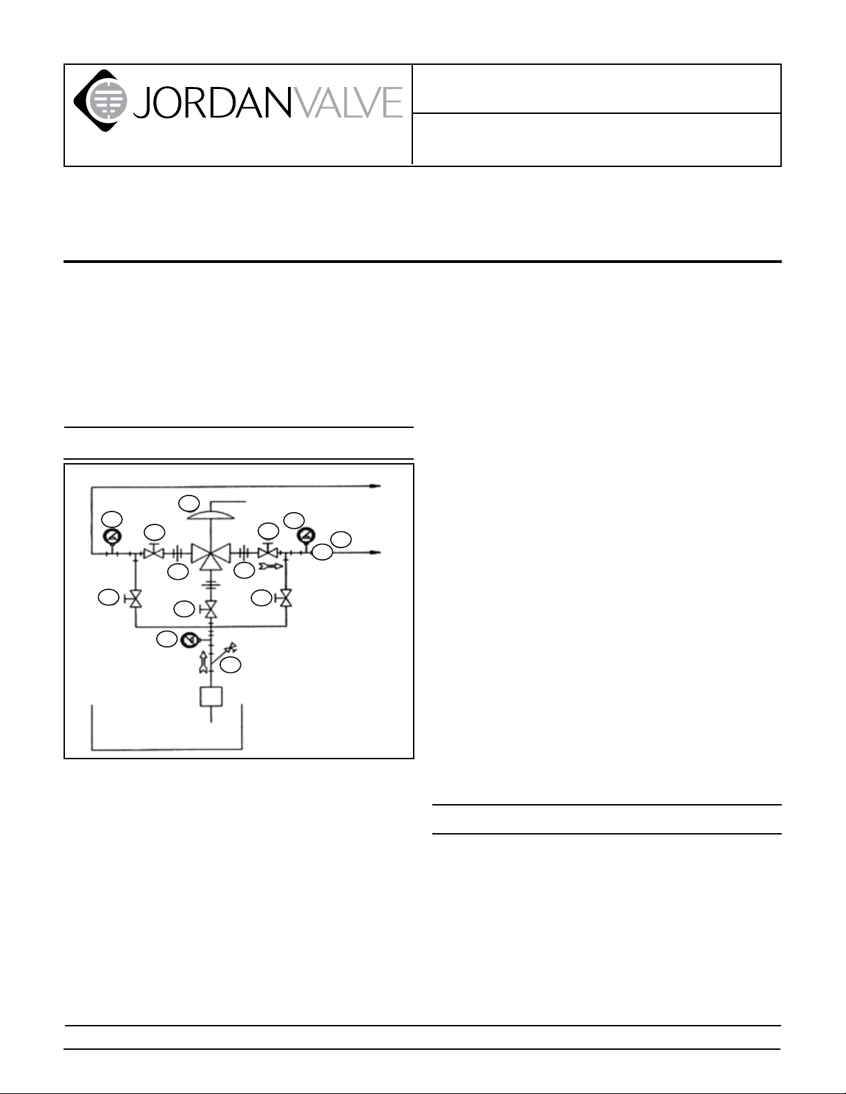
Main Line
4
1
Ideal Installation
Control Valve
4
1
1
1. Shut off Valve
2. Pipe Union
3. Strainer and Drain Valve
4. Pressure Gauge
5. Jordan Series 790 DCV
6. Relief Valve
1
2
1
4
Pump
Reservoir
5
2
3
6
R
in the direction of ow. The valve may be installed
vertically or horizontally without affecting its operation.
For best control, 3’ 0” straight sections of pipe 7.
should be installed on either side of the valve.
In hot vapor lines, upstream and downstream pip-8.
ing near the valve should be insulated to minimize
condensation.
If possible, install a relief valve downstream from 9.
the valve. Set at 15 psi above the control point of
the valve.
Expand the outlet piping at least one pipe size if 10.
the controlled pressure (downstream) is 25% of
the inlet pressure or less. A standard tapered expander connected to the outlet of the valve is recommended.
Where surges are severe, a piping accumulator is 11.
recommended.
The air piping or tubing to the diaphragm case 12.
should be 1/4” or 3/8”. The length of tubing should
To protect the valve from grit, scale, thread chips 1.
be less than 150 feet.
and other foreign matter, ALL pipelines and piping
components should be blown out and thoroughly
Start Up
cleaned before the installation process begins.
Shutoff valves, pressure gauges and by-pass piping 2.
should be installed as indicated in the Ideal Installation Schematic to provide easier adjustment, operation, and testing.
In preparing threaded pipe connections, care 3.
should be exercised to prevent pipe-sealing compound from getting into the pipe lines. Pipe sealing compound should be used sparingly, on male
threads only, leaving the two lead threads clean.
Jordan uses and recommends Seyco #2415 thread
The MK79 Control Valve has been pre-set by 1.
Jordan; however, ner adjustments may be
required to compensate for pressure drops of
the application. See the “Spring Pre-Loaded
Adjustment” section.
Close all inlet, outlet and by-pass shut-off valves. 2.
Remove all pressure from downstream lines.
Fully open the outlet shut-off valves. Slowly open 3.
the inlet shut-off valve just enough to start ow
through the control valve. Increase the ow
PROTECT VALVES WITH LINE STRAINERS
Page 2

gradually by slowly opening the inlet shut-off valve.
DO NOT fully open the inlet shut-off valve until you
are sure that the controller and control valve have
control of the system.
To shut off the line uid, close the inlet shut-off 4.
valve rst, then the outlet shut-off valves.
Body and cap bolts should be re-tightened per 5.
torque procedures after valve reaches operating
temperature.
Maintenance
Caution: Be sure that there is no pressure in the valve
before loosening any ttings or joints. The following
steps are recommended:
Close inlet shut-off valve.1.
Allow pressure to bleed off through downstream 2.
piping. Do not cause a reverse ow through valve
by bleeding pressure from the upstream side of
valve.
Shut off air supply to controller and remove control 3.
air line from the valve.
Valve Seats
The valve seats in all Jordan valves are lapped to
a critical atness. Maintaining such tolerances is
of paramount importance for your assurance of
excellent control and tight shut-off. Do not use
metallic objects in removing the seats. Care in
handling is imperative.
A. DISASSEMBLY
Shut off pressure to the valve. See caution above.1.
Remove the valve from the line.2.
Note the scribed line on the side of valve body and 3.
caps. Secure one of the outlet cap hexes (1) in a
vise. Remove the cap screws (2) from the other cap
and lift the cap straight up.
Next remove the valve plate (3) and place it on the 4.
bench with the lapped surface up. You will notice
that there is a locating pin which aligns the valve
plate with the disc guide (5). The scribe line on the
outside of the valve cap and valve body indicates
that this locating pin should be on this side.
Now remove the valve disc (4) and the disc guide 5.
(5), placing the valve disc on the bench with the
lapped surface up. Fingertip pressure should be
sufcient to remove these parts.
leakage or improper control.
Clean all parts of the body and cap with a good 6.
quality solvent. The valve disc and the valve plate
then may be cleaned. Place a piece of 4/0 polishing cloth or jeweler’s cloth on a smooth, at surface, and polish the lapped surfaces. If the parts
are badly scarred, DO NOT attempt to re-lap them,
but return to the factory for repair or replacement.
USE ONLY JORDAN REPLACEMENT PARTS. The
use of other than genuine Jordan parts may impair
their ability to serve you.
B. REASSEMBLY
On the normally open side, place the disc guide in 1.
the body bore with the index pin on the same side
as the scribe line on the valve body. Apply a small
amount of anti-seize compound to the body bore.
Place the disc in the aperture of the disc guide and 2.
engage the disc pin.
In placing the plate in the body, notice that the 3.
index pin hole in the lapped surface of the plate
engages the index pin of the disc guide.
On Normally Open Side4. : with no pressure on the
actuator, the disc and plate should have the orices
in perfect alignment, with the slots at 90° to the
stem. It may be necessary to move the seat set in
the bore to obtain this critical positioning. On Nor-
mally Closed Side: apply 20-25 psi to the actuator
to assure the valve is stroked fully. Follow alignment
instructions for Normally Open Side.
Apply a small amount of anti-seize compound to 5.
the cap bore and set the cap onto the plate, being
careful not to move the position of the plate.
Tighten the cap screws uniformly, being cautious 6.
not to apply too much torque. See table on page 4
for torque recommendations. Repeat disassembly
and reassembly per “A” and “B” above for second
set of seats.
Special Instructions for Mark 79MX:
All instructions for the MX version are the same as above
with the following modications:
The disc pin protrudes through the plate, with the 1.
disc and disc guide located on top.
Upon start-up, it is important to simultaneously 2.
open both inlets slowly. If only one can be done at
a time, open the normally closed side rst.
It is imperative that the disc pin is not rotated in
disassembly, cleaning, or reassembly, since this
affects the stroke adjustment of the valve.
Improper handling of the seats will result in
Disc Pin
Remove the valve disc and plate (3, 4) following the 1.
procedure outlined under “VALVE SEATS” above.
Loosen the stem connector nut and bolt (19, 20) 2.
and remove connector assembly (18).
-2-
Page 3

Back out the four alien head set screws (22) which 3.
will allow the valve body (12) to be separated from
the valve yoke (21).
Loosen the disc pin nut (7) and rotate the disc pin 4.
(6) counterclockwise, pulling valve stem (17) upward while doing so. DO NOT remove the valve
stem completely but raise it sufciently so that the
disc pin may be removed by pulling up and out.
Replace the disc pin so that the cast “B” on the disc 5.
pin faces up and is on the normally open side of
the body and reassemble in reverse order following
the procedures outlined under “VALVE SEATS” and
“STROKE ADJUSTMENT”.
the plate by moving the stem adaptor in or out
of the actuator stem until the seats are in perfect
alignment, in the fully open position.
After perfect alignment is obtained, tighten the 4.
stem adaptor lock nut and the stem connector bolt.
Recheck the seat alignment to check that nothing
has moved.
To check the normally closed side, apply 20-25 psi 5.
signal to the actuator. If the seats are not in perfect
alignment, refer to “Valve Seats – Reassembly, Step
4.”
Diaphragm Replacement
Packing
To replace the packing, the valve need not be removed
from the line; however, PRESSURE MUST BE REMOVED
FROM THE VALVE!
Remove connector assembly (18).1.
Remove both packing ange nuts (16).2.
Remove packing ange (14) and packing follower 3.
(13).
Should packing spring (9) not eject packing set 4.
(10), a slight amount of upstream pressure might
be necessary to remove the packing set. (Note: on
Mark 79MX version, downstream pressure might
be necessary to remove packing.)
Remove packing retainer (11) and packing spring 5.
(9).
Clean packing bore with solvent and blow out thor-6.
oughly.
Assemble in reverse order and tighten packing nut 7.
(16) so that packing follower (13) bottoms out on
top of valve body.
Engage valve stem (17) and actuator stem (27) with 8.
connector. Tighten connector nut and bolt. No
stroke adjustment is required.
Valve Stroke Adjustments
If the valve requires a stroke adjustment after maintenance on one of the above points, follow these procedures.
Make sure that the actuator stem (27) is stroked 1.
fully upward by the spring (29) [no pressure on actuator.]
Loosen the stem connector nut (20) only enough 2.
to allow the stem adaptor to rotate. DO NOT remove the stem connector (18). Proper positioning
of the valve stem and actuator stem must be maintained during adjustment of seats.
Orices on the disc and plate must be in perfect 3.
alignment, in the full open position, on the normally
open seats. Adjust the position of the disc on
To replace the diaphragm, the valve need not be removed from the line, however, PRESSURE MUST BE REMOVED FROM THE ACTUATOR.
Remove the control air line from the actuator1.
Remove the stem connector (18) by removing stem 2.
connector bolt and nut (19, 20).
Remove compression from springs (29) by turning 3.
actuator stem (27) clockwise (when viewed from
top of the valve).
Remove the actuator case bolts and nuts (37, 38) 4.
and lift the upper case (36) off of the lower case
(28).
Screw the actuator screw (30) completely out of 5.
the actuator stem (27). Remove the diaphragm assembly.
Remove the two lock nuts (31) and remove the dia-6.
phragm plate (32) and the diaphragm (33) from the
actuator screw (30).
Clean all parts with a good quality solvent. Remove 7.
encrusted material with crocus or very ne aluminum oxide cloth. Inspect all parts for excessive
wear and/or damage. Replace the worn or damaged parts. USE ONLY JORDAN REPLACEMENT
PARTS. The use of other than genuine JORDAN
parts may impair their ability to serve you.
Reassemble Actuator:8.
Assemble the seal (35), diaphragm stop (34), a.
diaphragm (33), and diaphragm plate (32) to
actuator screw (30). Assemble and tighten
two lock nuts.
Place the six springs (29) in lower case (28) b.
so that they nest over the six screw heads
(26).
Thread the actuator stem (27) onto the actua-c.
tor screw until the springs are slightly compressed. The formed bosses in the diaphragm
plate must also nest in the springs.
Replace the upper case (36).d.
Replace four of the actuator case bolts and e.
nuts (37, 38) 90° apart and tighten ngertight. Replace the remaining bolts and nuts
and tighten evenly alternating across the actuator case.
-3-
Page 4

Adjust spring preload. See “SPRING PRELOAD AD-9.
JUSTMENT” section.
Spring Pre-Loaded Adjustment
valve might be determined using the following information: Model Number, Valve Body Size, Seat Material and
Cv Rating, Spring Range and Set Point, Trim Material, Part
Name - Number and Quantity.
The signal range (3 to 15 psi, or other) is preset by
Jordan; however, when the valve is installed this range
may shift slightly due to pressure drops across the valve.
Additionally, preload adjustment may be required after
one of the previous maintenance procedures.
Remove the air signal line from the actuator and 1.
replace with a pressure gauge and an air regulator.
Loosen, but do not remove, the stem connector 2.
bolt and nut (19, 20).
Adjust the actuator air pressure to just below the 3.
starting point of the range and rotate the actuator
stem (27) until the stem just starts to move. Continue to rotate the actuator stem about one-half
turn. Remove the air pressure. Increase the air pressure and check the pressure at which the valve just
starts to move. Repeat actuator stem adjustment if
necessary and again check pressure at which the
stem starts to move.
After the preload has been properly adjusted, tight-4.
en the stem connector bolt and nut, and reattach
the control air line.
Trouble Shooting
NOTE: Any parts ordered without a valve serial number
that are found to be incorrect are subject to up to a minimum 25% restock charge when returned.
Torque Values
Torque for bolts connecting valve cap to valve body;
torque in sequence shown to the following values:
Cast Iron, Ductile Iron or
Bronze Valves
140 in. - lbs. 150 in. - lbs.
5
3
2
(or multiples)
1
4
6
6 bolts
Carbon Steel or Stainless
Steel Valves
3
7
5
2
(or multiples)
1
6
8
4
8 bolts
If You Experience Erratic Control:
Oversizing causes cycling and hunting and reduces
the rangeability of the valve. Make certain that your
sizing is correct.
Steam traps downstream may need attention.
Safety valve may be jammed open. Repair as nec-
essary.
Excessive foreign matter on seats. Clean them.
Valve stroke out of adjustment. Check and readjust
if necessary.
Valve disc may not be moving freely.
If Valve Will Not Operate:
Diaphragm may be ruptured. Replace as needed.
Adjusting spring broken. Replace as needed.
Improper spring setting. Reset as needed.
Ordering Spare Parts
Use only genuine Jordan Valve parts to keep your valve
in good working order. So that we can supply the parts,
which were designed for your valve, we must know exactly which product you are using. The only guarantee to
getting the correct replacement parts is to provide your
Jordan Representative with the valve serial number. This
number is located on the valve identication tag. If the
serial number is not available, the parts needed for your
-4-
Page 5

41
40
20
16
14
22
13
Illustration and Parts List
Item Description Qty.
1 Cap 2
29
12
36313430353226
37
38
28
25
27
23
19
18
15
21
10
11
9
17
6
2
33
1
7
4
3
5
MK79
MK79MX
2 Cap Bolts 12
*3 Plate 2
*4 Disc 2
*5 Disc Guide 2
*6 Disc Pin 1
*7 Disc Pin Nut 1
9 Packing Spring 1
*10 Packing Set 1
11 Packing Retainer 1
12 Body 1
13 Packing Follower 1
14 Packing Flange 1
15 Packing Stud 2
16 Packing Stud Nut 2
*17 Stem 1
18 Stem Connector 2
19 Stem Connector Bolt 1
20 Stem Connector Nut 1
21 Yoke 1
22 Yoke Set Screw 4
23 Yoke Adaptor Screw 4
25 Adaptor Plate 1
26 Screw 6
27 Actuator Stem 1
28 Lower Actuator Case 1
29 Spring 6
30 Actuator Screw 1
31 Locknut 2
32 Diaphragm Plate 1
33 Diaphragm 1
34 Diaphragm Stop 1
35 Seal 1
36 Upper Actuator Case Assembly 1
37 Bolt 3
38 Nut 3
40 Stem Adaptor 1
41 Locknut 1
42 Index Pin (not shown) 4
* Recommended Spare Parts
Bulletin IM-MK79-0909
3170 Wasson Road • Cincinnati, OH 45209 USA
Phone 513-533-5600 • Fax 513-871-0105
info@richardsind.com • www.jordanvalve.com
 Loading...