

Page 1
I & M Mark 78 Series
3170 Wasson Road • Cincinnati, OH 45209 USA
Phone 513-533-5600 • Fax 513-871-0105
info@richardsind.com • www.jordanvalve.com
Installation & Maintenance Instructions for
Mark 78 Control Valves (1/2” - 1”)
Warning: Jordan Valve Control Valves must only be used, installed and repaired in accordance with these Installation & Maintenance Instructions. Observe all applicable public and company codes and regulations. In the event
of leakage or other malfunction, call a qualified service person; continued operation may cause system failure or a
general hazard. Before servicing any valve, disconnect, shut off, or bypass all pressurized fluid. Before disassembling
a valve, be sure to release all spring tension.
Please read these instructions carefully!
shipment from Jordan Valve.
5. Install the valve in the highest horizontal line of pipYour Jordan Valve product will provide you with long, trouble-free service if it is correctly installed and maintained.
Spending a few minutes now reading these instructions
can save hours of trouble and downtime later. When making repairs, use only genuine Jordan Valve parts, available
for immediate shipment from the factory.
ing to provide drainage for inlet and outlet piping, to
prevent water hammer and to obtain faster response.
6. The flow arrow on the regulator body must be pointed
in the direction of flow. The valve may be installed vertically or horizontally without affecting its operation.
7. For best control, 3’ 0” straight sections of pipe should
be installed on either side of the valve.
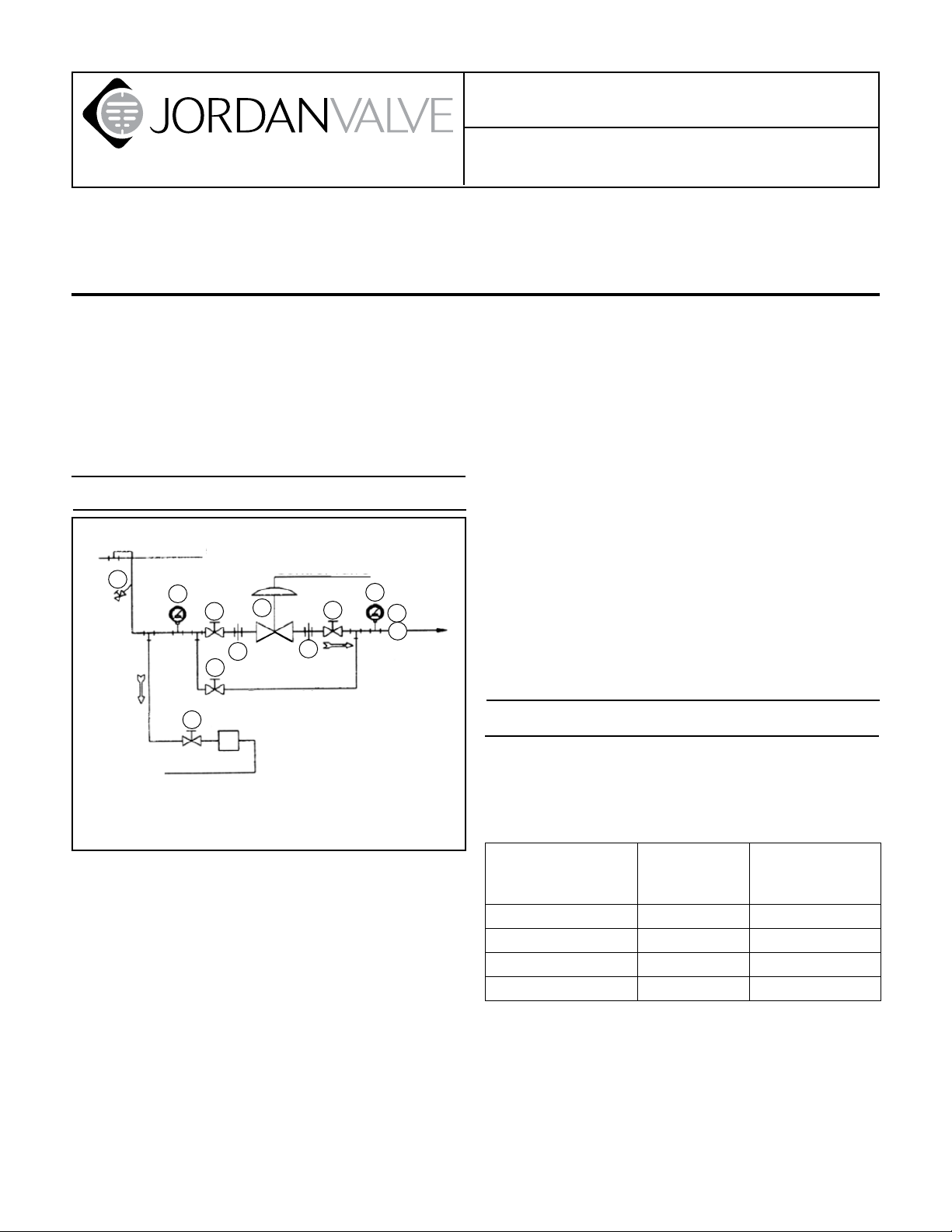
Ideal Installation
8. In hot vapor lines, upstream and downstream piping
near the valve should be insulated to minimize condensation.
Main Line
3
4
1
Condensate Return
Control Valve
4
1
1
5
2
Bypass Line
1
2
1. Shut off Valve
2. Pipe Union
3. Strainer and Drain Valve
4. Pressure Gauge
5. Control Valve
6. Relief Valve
6
R
9. If possible, install a relief valve downstream from the
valve. Set at 15 psi above the control point of the valve.
10. Expand the outlet piping at least one pipe size if the
controlled pressure (downstream) is 25% of the inlet
pressure or less. A standard tapered expander connected to the outlet of the valve is recommended.
11. Where surges are severe, a piping accumulator is rec-
ommended.
Start-Up
1. Be sure that the action of the control valve and the
controller are such as to give the desired results. See
“Reversing Action” to change the valve action if necessary.
1. To protect the valve from grit, scale, thread chips, and
other foreign matter, all pipe lines and piping components should be blown out and thoroughly cleaned
before the valve is installed.
2. Shutoff valves, pressure gauges, and bypass piping
should be installed as indicated in the diagram to provide easier adjustment, operation, and testing.
3. In preparing threaded pipe connections, care should
be exercised to prevent pipe sealing compound
from getting into the pipe lines. Pipe sealing compound should be used sparingly, leaving the two lead
threads clean.
4. A line strainer should be installed on the inlet side of
the regulator to protect it from grit, scale and other
foreign matter. A 0.033 perforated screen is usually
suitable. Line strainers are available for immediate
If an increase
in pressure or
temperature must:
And the
action of the
valve is:
Then the action
of the controller
must be:
Close Valve Air to Close Direct
Close Valve Air to Open Reverse
Open Valve Air to Close Reverse
Open Valve Air to Open Direct
2. The control valve has been pre-set by Jordan Valve.
However, finer adjustments may be required to compensate for pressure drop conditions of the application.
3. With the inlet, outlet and bypass shutoff valves closed,
and no pressure in the downstream line, fully open the
shutoff valve. Slowly open the inlet valve just enough
Page 2

to start flow through the control valve. Increase flow
gradually by slowly opening the inlet shutoff valve. Do
not fully open the inlet valve until you are sure that
the controller and control valve have control of the
system. Usually, the handwheel on the inlet valve will
turn freely when this point is reached.
4. To shut off the line fluid, close the inlet shut-off valve
first, then the outlet shut-off valves.
Maintenance
To reduce maintenance time, refer to proper figure
and follow steps indicated below for applicable maintenance operation.
Proposed Maintenance
Procedure
Renewing stem packing Packing Replacement
Valve disassembly, inspecting
parts, replacing plug or seat ring
Valve Reassembly Valve Reassembly
Actuator spring preload
adjustment
Actuator maintenance Actuator Maintenance
Changing valve action Reversing Action
Routine maintenance should be expected due to normal wear and tear, damage from external sources or debris. The regulator components, especially the moving
and sealing parts, should be inspected periodically and
replaced as necessary. Frequency of inspection/replacement depends upon severity of conditions, but may also
be required by local/state/federal law or industry standards.
Follow Steps...
Valve Disassembly
Actuator Spring
Preload Adjustment
Packing Replacement
Renew valve plug stem packing if control valve has been
in service beyond normal maintenance, and packing
shows signs of wear. Wear will be indicated by leakage
which cannot be corrected by minor tightening of packing flange.
An additional packing ring can be installed to overcome
minor leakage without dismantling the control valve or
breaking valve plug connection.
1. Disassemble control valve as far as necessary for the
work required (see “Valve Disassembly”). Remove
packing. Clean valve plug stem (9) and packing box
thoroughly. Polish valve plug stem (9) with crocus
cloth. Use approved non-residue-forming solvent for
cleaning. Wipe dry with clean cloth.
2. Insert a new set of packing (13) in packing box. Press
each ring down in place with a tube as it is installed.
3. After packing is installed, assemble packing follower
(11), packing nut (15) to bonnet (4).
Valve Disassembly
1. Close inlet and outlet stop valves. Operate system bypass if necessary.
2. Following instructions according to valve action:
3a. Direct Acting Actuator (ATC): shut off operating me-
dium and relieve pressure from diaphragm by disconnecting tubing at diaphragm case. To remove the actuator from the valve body assembly: loosen the two
stem nuts (28) and move down the stem (9). Lock the
nuts together and, using a wrench on these nuts and
the flats on the stem connector (34), turn the valve
stem out of the stem connector threads until it disengages. Loosen and remove the four yoke bolts (6)
and lift the actuator assembly from the bonnet (4).
3b. Reverse Acting Actuator (ATO): apply air pressure to
actuator to lift plug off of seat. To remove the actuator
from the valve body assembly: loosen and remove
the four yoke bolts (6) and lockwashers (8). Loosen
the two stem nuts (28) and move down the stem (9).
Lock the nuts together and, using a wrench on these
nuts and the flats on the stem connector (34), turn
the valve stem out of the actuator stem threads until it
disengages. Lift the actuator assembly from the bonnet (4).
4. Loosen packing nut (15).
5. Remove bonnet (4), o-ring (29), compressor (5) and
cage (2) from the body (1).
6. Remove support washer (42) [on soft seated valves
in 1/2” – 3/4” sizes only], seal (41) [soft seated valves
only], seat (3), and seat o-ring (30) from the body.
7. Remove the two stem nuts (28) from the stem (9).
8. Remove plug/stem (9) from the bonnet (4).
9. Remove packing nut (15), packing follower (11) and
packing (13).
10. Cleaning: clean all parts with an approved, non-residue-forming solvent. Remove encrusted materials
with crocus or very mild aluminum oxide cloth. Clean
packing box thoroughly.
11. Inspect all parts including plug, seal and seat. Replace any badly worn or damaged parts.
12. Replacing Seats (Hard Seated Valves Only): if seat is
badly worn or damaged, it should be replaced. Very
minor cuts on the seating surface, however, may be
lapped out. NEVER lap to the extent that the valve
plug becomes grooved.
13. Lapping in Valve Plug & Seat Ring: replace valve plug
(9) in bonnet (4). Apply superfine lapping compound
to valve plug seating surface at several points. Replace seat o-ring (30) and seat (3) in body (1). Reassemble bonnet (4) to body (1). Use stem to align
seat to plug in the body. Lap valve plug and seat ring
in until a fine continuous ring of contact has been
made on both surfaces. DO NOT lap until a ridge is
formed in valve plug seating face. A few turns are suf-
-2-
Page 3

ficient. When lapping, turn valve plug in short arcs
and occasionally lift valve plug off seat ring and turn
in 1/4 turn to maintain even distribution of lapping
compound. When lapping is completed, disassemble
bonnet from body and remove all traces of lapping
compound.
Valve Reassembly
1. Place seat o-ring (30) on seat (3) [use small amount
of grease to hold these parts together] and place in
valve body (1). Place seal (41)(soft seated valves) and
support washer (42)(1/2” & 3/8” only) into groove in
seat (3). Place cage (2) and compressor (5) into body.
2. Assemble stem/plug (9) to bonnet (4).
3. Reassemble the o-ring (29) and bonnet (4) to the
valve body (1) making sure that seat o-ring (30), compressor (5), cage (2), seat (3), seal (41), and support
washer (42) are properly in place.
4. Install a new set of packing (13) as described in “Packing Replacement”.
5. Reassemble two stem nuts (28) and indicator washer
(12) to valve stem (9).
6. Insert threaded end of bonnet (4) through hole in
yoke (33) and secure actuator to the body with four
bolts (6) and lockwashers (8). Tighten to 10 ft/lbs.
7. Lift the valve stem (9) and thread it into the stem
connector (34) at least one diameter. Adjust actuator
spring preload as described in the following section.
Actuator Spring Preload Adjustment
(Starting Pressure)
Caution: Do not apply more than 45 psig to actuator.
Direct Acting Actuator (ATC): Actuator spring pre-
load adjustment can be made either with or without
pressure in valve body. Once correct compression is
made, no further adjustment is necessary.
Reverse Acting Actuator (ATO): Note: ATO 3-15
psig rated valves are bench set at the factory at 5-17
psig. Please insure that any I/P utilized with this control valve is capable of 17 psig output to ensure full
valve travel. If desired, the range may be changed to
suit your needs by following the instructions below.
The valve plug is closed against upward fluid thrust
by actuator spring force. Total compression placed on
actuator spring must be sufficient to provide the reload plug force required to close the valve. If preload
adjustment is made with no pressure in valve body,
then, when the control valve is placed in operation,
body, then, when the control valve is placed in operation, additional compression must be placed on the
spring to provide valve closure force. With proper adjustment, valve will close tightly and will not begin to
open until the preload pressure is exceeded.
Adjusting Spring Preload:
1. Loosen two stem nuts (28), move down the stem (9)
and lock two stem nuts together.
2. Connect control air supply line with a pressure gauge
to the diaphragm case (16 for ATO or 26 for ATC).
3. Direct Acting Actuator (ATC 3-15 Range):
Note: If range is other than 3-15, adjust preload to low
end of range.
Adjust spring preload until valve starts to close
when 3 psig air pressure is supplied to the actuator
diaphragm. If there is valve movement at less than
3 psig: thread the valve stem (9) into the stem connector (34), wrenching on locked stem nuts (28) on
stem connector (34) to increase the spring preload.
If there is no movement at 3 psig: thread the valve
stem (9) out of the stem connector (34) to decrease
the spring preload.
4. Reverse Acting Actuator (ATO 3-15 Range): Jordan
control valves rated 3-15 (ATO) are bench set at the
factory at 5-17 psig. Please insure that any I/P utilized
with this control valve is capable of 17 psig output to
ensure full valve travel. If desired, the range may be
changed to suit your needs by following the instructions. In general, adjust 3-15 range to 5 psig; all other
ranges are adjusted to the low end of the range.
Adjust spring preload until valve just starts to open
when 5 psig air pressure is supplied to the actuator
diaphragm. If there is valve movement at less than 5
psig: thread the valve stem (9) out of the stem connector (34), wrenching on locked stem nuts (28) and
flats on stem connector (34) to increase the spring
preload. If there is no valve movement at 5 psig:
thread the valve stem (9) into the stem connector
(34), wrenching on locked stem nuts (28) and flats on
stem connector (34) to decrease the spring preload.
Note: alternately adjust preload and check pressure
to start valve movement by raising pressure to 5 psig
(or pressure required to start movement) until proper
adjustment is attained.
5. After proper spring preload has been attained, loosen
two stem nuts (28), thread them along with the indicator washer (12) up the stem (9) and lock against the
end of the stem connector (34). If necessary, adjust
the position of the travel indicator (35) by loosening
screw(s) (37) and moving the travel indicator until it is
properly aligned with the indicator washer (12).
Note A: a control valve which has been adjusted to
provide 3 psig starting pressure plus valve closure
force (with pressure in body) will have a considerably
higher start-pressure than 3 psig, when tested at 0
body pressure.
-3-
Page 4

Note B: air pressures quoted are relative. Actual pressures required in operation may vary with pressure
drop conditions existing and/or actuator springs used.
Actuator Maintenance
Disassembly and Inspection of Actuator
1. Close inlet and outlet stop valves. Operate system bypass, if necessary. Remove the actuator as described
in “Valve Disassembly”, Step 3.
2. Remove the nuts (27) and bolts (7) which hold the upper actuator case (26) to the lower actuator case (16)
and remove the upper actuator case.
3a. Direct Acting Actuator (ATC): remove the actua-
tor stem bolt (45) and lift the fastener seal (21), seal
washer (22), diaphragm (23), diaphragm plate (24),
and spacer (38) from the actuator stem. Remove the
actuator stem (17). To check the stem o-ring (31), unscrew the gland nut (20) from the gland (19) and remove the bushing (36) and stem o-ring from the end
of the actuator (16).
3b. Reverse Acting Actuator (ATO): remove springs (25)
from diaphragm plate (24). Remove the actuator stem
bolt (45) and lift spacer (38), diaphragm plate (24),
diaphragm (23), seal washer 22) and fastener seal
(21) from the actuator stem (17). Remove the actuator stem (17). To check the stem o-ring (31), unscrew
the gland nut (20) from the gland (19) and remove
the bushing (36), and stem o-ring from the end of the
gland.
4. Clean all parts with an approved, non-residue-forming
solvent. Remove encrusted material with crocus or
very mild aluminum oxide cloth. Inspect all parts for
excessive wear and/or damage. Replace any worn or
damaged parts.
Reassembly of Actuator
After all parts have been thoroughly cleaned and inspected, reassemble the actuator.
1. Direct Acting Actuator (ATC): insert the actuator stem
(17) through the gland (19), greasing stem o-ring (31),
if available, before inserting the actuator stem and
bushing (36) and gland nut (20). Place the springs
(25) in the lower actuator case (16). Place the spacer
(38), diaphragm plate (24) on the springs so that the
stamped bosses are nested in the springs. Install the
diaphragm (23) so the bolt holes line up with the bolt
holes in the lower actuator case. Place the seal washer (22) on the diaphragm and bolt together with the
seal ring (21) and actuator stem bolt (45) and tighten.
2. Reverse Acting Actuator (ATO): lightly grease the
stem o-ring (31) and install in the c’bore in the gland
(18), bushing (36), gasket (18) and gland nut (20).
Thread actuator stem (17) through the gland. Assem-
ble the spacer (38) [55M actuators only], diaphragm
plate (24), diaphragm (23), seal washer (22) and fastener seal (21) to stem actuator bolt (45) and thread
into the actuator stem (17). Line up the bolt holes in
the diaphragm with the holes in the lower diaphragm
case. Place the springs (25) on the diaphragm plate
nested over the punched bosses.
3. Place the upper actuator case (26) on the diaphragm,
lining up the bolt holes.
4. Replace four bolts (7) and nuts (27) 90° apart and
tighten finger-tight. Replace the remainder of the bolts
and nuts and tighten evenly and alternate across the
actuator case.
5. Thread the valve stem (9) into the stem connector
(34) and adjust the spring preload as described previously (“Actuator Spring Preload Adjustment”).
Reversing Action
Changing the valve action from direct to reverse acting or
from reverse to direct acting.
Different actuator springs are required to meet the published pressure drop ratings when changing action. Failure to do so will change the allowable pressure drop capability of the valve. Consult factory for details.
The action of the Mark 78 control valve is reversed by
reversing the action of the actuator.
1. Disassemble the actuator as described in “Actuator
Maintenance”.
2. Reassemble the actuator with the desired action. Refer to “Actuator Maintenance”.
Troubleshooting
If you Experience Erratic Control:
Oversizing causes cycling or hunting – recalculate
size required.
Undersizing causes control setting to drop under
peak loads.
Steam traps downstream may need reconditioning.
Safety relief valve may be jammed open.
Excessive foreign matter may be lodged in seats.
Valve stroke may be out of adjustment.
Valve plug may not be moving freely.
Inlet pressure may be too low.
If You Experience Insufficient Flow:
Check shutoff valves to be sure they are fully open.
Check pressure on upstream side (install a pressure
gauge on the upstream side).
Blow down strainers.
Clean all traps and be sure they are in good working
order. If the return line from the trap is cool, the steam
coil may be clogged.
-4-
Page 5

If You Experience Overriding:
Usually caused by scale or foreign matter holding the
plug open - inspect and clean or replace.
May be caused by failure of the diaphragm – replace
diaphragm as needed.
May be caused by too high a spring setting – adjust
if necessary.
May be caused by insufficient instrument output pres-
sure.
If You Experience Leakage or Erratic Regulation:
Excessive pressure drop - reduce with pressure regu-
lating valve.
Plug may be binding.
There may be excessive foreign matter in seat.
Ordering Spare Parts
Use only genuine Jordan Valve replacement parts! Replacement parts for this Jordan Valve product are kept in
stock for immediate shipment. The use of other than genuine Jordan Valve parts may impair their ability to serve
you. Jordan parts are held to close tolerances to eliminate
field machining and grinding (on plugs and rings) or reaming (plug guide bushings).
When ordering parts, refer to the drawings at the end of
this document and reference the appropriate part name.
When ordering replacement parts, please supply the following information: valve model name, serial number (if
available), part name, actuator size, body material, valve
action and Cv.
-5-
Page 6

Illustration and Parts List
(Reverse Acting Shown)
26
25
7
27
16
23
24
33
4
8 6
38
45
22
35
20
17
37
34
9
11
31
36
12
28
28
15
13
14
10
29
5
2
44
21
21
19
18
3
30
2
3
30
Section of 1/2” and 3/4”
Orifice Soft Seat
1
2
42
3
41
30
1/2” – 1” with
35M Actuator
Section of 1” Orifice
Soft Seat
41
Item Description Qty Item Description Qty Item Description Qty.
1 Body 1 15 Packing Nut 1 29 O-Ring 1
2 Cage 1 16 Lower Actuator Case Assy 1 30 O-Ring 1
3 Seat 1 17 Actuator Stem 1 31 O-Ring 1
4 Bonnet 1 18 Gasket 1 33 Yoke 1
5 Compressor 1 19 Gland 1 34 Stem Connector 1
6 Hex Bolt, Bonnet 4 20 Gland Nut 1 35 Travel Scale 1
7 Hex Bolt, Actuator 8 21 Fastener Seal 7 36 Stem Bushing 1
8 Lockwasher 4 22 Seal Washer 1 37 Machine Screw 1
9 Plug/Stem 1 23 Diaphragm 1 38 Spacer 1
10 Packing Spring 1 24 Diaphragm Plate 1 41 Seal (Soft Seat only) 1
11 Packing Follower 1 25 Spring (3-15 Range) 6 42 Support Washer (Soft Seat Only) 1
12 Washer 1 26 Upper Actuator Case Assy 1 43 Air Vent (Spring Side) 1
13 Packing Set 1 27 Hex Nut 8 44 Hex Bolt, Yoke 6
14 Packing Retainer 1 28 Stem Nut 3 45 Hex Bolt, Actuator Stem 1
-6-
Page 7

Illustration and Parts List – Actuators
27
7
23
26
16
43
18
25
31
36
45
38
17
26
24
22
45
21
38
7
27
23
25
18
19
20
17
31
36
16
55IN2 Reversible Actuator (Direct Acting Shown) Scale 1:2
24
22
21
20
19
43
55IN2 Reversible Actuator (Reverse Acting Shown) Scale 1:2
7
27
35IN2 Reversible Actuator (Direct Acting Shown) Scale 1:2
Bulletin IM-MK78-0311
26
16
18
25
24
19
45
21
17
3170 Wasson Road • Cincinnati, OH 45209 USA
Phone 513-533-5600 • Fax 513-871-0105
info@richardsind.com • www.jordanvalve.com
20
36
22
38
31
23
43
 Loading...