

Page 1
I & M Mark 75 (1” – 2”)
3170 Wasson Road • Cincinnati, OH 45209 USA
Phone 513-533-5600 • Fax 513-871-0105
info@richardsind.com • www.jordanvalve.com
Installation & Maintenance Instructions for
Mark 75 Wafer Control Valve
Warning: Jordan Valve Control Valves must only be used, installed and repaired in accordance with these Installation & Maintenance Instructions. Observe all applicable public and company codes and regulations. In the event
of leakage or other malfunction, call a qualified service person; continued operation may cause system failure or a
general hazard. Before servicing any valve, disconnect, shut off, or bypass all pressurized fluid. Before disassembling
a valve, be sure to release all spring tension.
Please read these instructions carefully!
should be installed on either side of the valve.
5. The disc in the valve body must be positioned
Your Jordan Valve product will provide you with long,
trouble-free service if it is correctly installed and maintained. Spending a few minutes now reading these instructions can save hours of trouble and downtime later.
When making repairs, use only genuine Jordan Valve
parts, available for immediate shipment from the factory.
in the upstream portion of the flow, and the setscrews should be on the downstream side of the
valve. Ideally for steam applications, the valve
should be installed in the highest horizontal line of
piping to provide drainage for inlet and outlet piping, to prevent water hammer, and to obtain faster
response.
6. If possible, install a relief valve downstream from
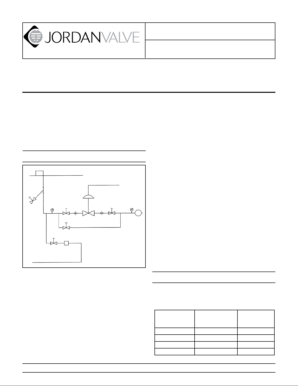
Ideal Installation
the valve. Set at 15 psi above the control point of
the valve.
Main Line
7. In hot vapor lines, upstream and downstream piping near the valve should be insulated to minimize
Control Air
condensation.
8. In gas service, expand the outlet piping at least
3
4
7
1
7
2
1
4
5
R
one pipe size, if the control pressure (downstream)
is 25 percent of the inlet pressure or less. A standard tapered expander connected to the outlet of
the valve is recommended.
9. Where surges are severe, a piping accumulator is
recommended.
1
1
6
Condensate Return Line
1. Shut off Valve
2. Jordan Control Valve
3. Strainer and Drain Valve
4. Pressure Gauge
5. Relief Valve
6. Steam Trap
7. Pipe Union
10. On steam control applications, install a steam trap
with sufficient capacity to drain the coil or condenser. Be sure to have a good fall to the trap, and no
backpressure. Best control is maintained if the coil
or condenser is kept dry.
11. Tighten pipe flange bolts just enough to effect a
good seal.
1. To protect the valve from grit, scale, thread chips
and other foreign matter, ALL pipelines and piping
components should be blown out and thoroughly
cleaned before the installation process begins.
2. Shutoff valves, pressure gauges and by-pass piping should be installed as indicated in the diagram
above to provide easier adjustment, operation, and
testing.
3. A line strainer should be installed on the inlet side
of the valve to protect it from grit, scale and other
foreign matter. A 0.033 perforated screen is usually
suitable for this purpose. Line strainers are available from Jordan Valve.
4. For best control, 3’ 0” straight sections of pipe
PROTECT VALVES WITH LINE STRAINERS
Start-Up Procedure
1. Be sure that the action of the control valve and of
the controller are such that you achieve the desired
results.
Increase in
pressure or
temperature must:
Close Valve Air to Close (Direct) Direct
Close Valve Air to Open (Reverse) Reverse
Close Valve Air to Close (Direct) Reverse
Close Valve Air to Open (Reverse) Direct
And the action of
the valve is:
Then the action
of the controller
must be:
Page 2

2. The control valve has been pre-set by Jordan Valve,
however, finer adjustment may be required to compensate for the system conditions of your application.
3. With inlet, outlet and bypass shutoff valves closed,
and no pressure in the downstream line, gradually
open the inlet valve enough to start flow through
the control valve. Increase the flow gradually by
slowly opening the inlet shutoff valve. Do not fully
open the inlet valve until you are sure that the
controller and control valve have control of the
system. Usually, the handwheel on the inlet valve
will turn freely when this point is reached.
4. To shut off the line fluid, close the inlet shutoff
valve first, and then close the outlet shutoff valve.
5. Loosen the body set screws (42).
6. It may be necessary to re-torque the pipe flange
bolts.
Maintenance
Caution: Make certain that there is no pressure in the
valve before loosening any fittings or joints. The following steps are recommended:
1. Close the inlet shutoff valve.
2. Allow pressure to bleed off through the downstream piping. Do not attempt to reverse the flow
through the valve by bleeding pressure from the
upstream side of the valve.
3. When the pressure gauges indicate that all pressure has been removed from the system, close the
outlet shutoff valve and the valve may be serviced.
Note: refer to the drawing at the end of this document
for description and proper orientation of parts.
Valve Seats
(28), Disc (27), and Gasket (36). Place the plate on
the bench with the lapped surface up.
5. Clean all parts of the Body (1) with a good quality
solvent. Remove Guide screws (35) and Guides
(34), the Disc (27) and Plate (28) can then be
cleaned. Place a piece of 4/0 polishing cloth or
jeweler’s cloth on a smooth flat surface such as a
surface plate and polish the Disc, and Plate lapped
surfaces using a figure “8” motion. If the parts are
scarred, do not attempt to re-lap them, but return
them to the factory for repair or replacement.
B. Reassembly
1. Place the plate (28) on a clean, flat work surface
with the lapped side up. The small single locator
hole should be towards you.
2. If the valve action is “air to open”, place the Disc
(27) on the Plate with the words “TOP REVERSE”
away from you. If the valve action is “air to close”,
the words “TOP DIRECT” should be away from you.
Move the Disc (27) until the slots are in perfect
alignment with those of the plate (28).
3. Place the Guides (34) on either side of the Disc
(27), and secure them with the Guide screws (35)
so that the Disc (27) can move freely up and down
but not side to side.
4. Lightly lubricate both side of the Body Gasket (36)
with an anti-seize compound. Place a new Body
Gasket (36) into the Body (1).
5. Hold the Plate / Disc assembly together and insert
it into the large end of the Body (1) with the slots
perpendicular to the stem (20), taking care that the
“T” slot in the Disc (27) engages the head of the
valve stem. The word ”TOP” should be towards the
actuator.
6. Replace the Set screws (42) in the Body (1).
7. Follow instructions under Installation & Start Up
Procedure when placing valve back in service.
A. Disassembly
The sliding Gate Seats of Jordan Valves are lapped to
light band flatness. Maintaining such tolerances is of
paramount importance for your assurance of excellent
control and tight shutoff. DO NOT use metallic objects
in removing the seats. Care in handling is imperative.
1. Tighten the body set screws (42). Follow instructions under the Maintenance section to remove
valve from line.
2. Disassemble the valve only as far as necessary to
do the required work.
3. When replacing seats it is recommended by Jordan
Valve that the packing be replaced if the valve is
older than one year. Follow the instructions under
Packing Replacement.
4. Remove the Set screws (42), and remove the Plate
Stem & Packing Replacement
1. Remove the Plate (28) and Disc (27), following the
procedure outlined under the Valve Seats section.
2. Loosen the Stem Connector Nut (31) and Bolt (30)
and remove Connector Halves.
3. Back out the Yoke SST Screws (29) and allow the
Body (1) to separate from the Yoke (3).
4. Remove the Packing Flange Nuts (43) and the
Packing Flange (24).
5. Before pulling the Stem (20) completely out of the
Body, you must remove the “7th” Stem T-Head (32)
by unscrewing it from the Stem (20). Remove the
Packing Assembly (37,38, & 40). The remaining
parts of the Packing Assembly can “fished” out with
a small screwdriver. (Be careful not to damage the
packing bore.)
6. Clean the packing bore in the Body with solvent
-2-
and blow dry.
Page 3

7. Clean the Stem (20) with solvent if it is to be reused.
8. Replace the Packing Spring (37) and Packing Retainer (38) in the packing bore.
9. Reassemble the new Packing (40) on the stem (20)
with the open part of the “V” downward (^). There
will be a flat on the top and bottom. Place the Packing Follower (23) on top of the Packing (40). (Coat
each piece of the packing set with a suitable lubricant.)
10. Gently push the Packing (40) into the packing bore
and place the Packing Flange (24) on the stem.
11. Put the Packing Flange Nuts (43) on the Packing
Studs (25) and partially tighten. At this point it is
recommended that you gently move the stem up
and down three or four times to align the assembly.
12. Tighten the Packing Flange nuts (43) until the Packing Follower (23) bottoms out on the top of the
body.
13. Reassemble Yoke (3) to the valve Body (1) with the
four Yoke Screws (29). Reassemble the Seats by
inserting in the body as outlined in Valve Assembly
Section.
Actuator
CAUTION: DO NOT apply more than 45 psi to the actuator.
The valve need not be removed from the line; however
before performing any maintenance on the actuator:
Since there will be no control of the valve available
it is recommended that the valve be isolated from
the service.
Shut off the control air supply and remove the con-
trol line from the actuator.
Remove the stem connector assembly (Stem
Adapter (22) to the Valve Stem (20) using the Stem
Connector Halves (21), the Stem Connector Bolt
(30) and Nut (31).
A. Actuator Disassembly
1. Remove the actuator assembly from the valve by
removing the four yoke Bolts (26), and lift the actuator assembly off the Yoke (3).
2. Place the actuator assembly on its top, (side with
the control line connection). Release the spring
compression, by threading the Actuator Stem (14)
out of the actuator, by turning it counterclockwise.
3. Remove the Actuator Bolts and Nuts (6,7) and
separate the two halves, (Upper Case [5] and Lower
Case [4]), of the actuator assembly. Remove the six
Range Springs (10) from the diaphragm plate (11).
4. Lift out the diaphragm assembly. Loosen and remove the two Actuator Jam Nuts (17) from the Actuator Bolt (16). Remove the Diaphragm Plate (11),
Diaphragm (15), Diaphragm Stop (13), and the Fastener Seal (18) from the Actuator Bolt (16) also.
5. Clean all parts with a good quality solvent. Remove
any encrusted material with crocus or very fine aluminum oxide cloth. Inspect all parts for excessive
wear and/or damage. Replace any worn or damaged parts. USE ONLY JORDAN REPLACEMENT
PARTS. The use of other than genuine JORDAN
parts may result in damage to the actuator, personal injury or property damage.
B. Actuator Reassembly
1. Place the Fastener Seal (18), Diaphragm Stop (13),
Diaphragm (15), and Diaphragm Plate (11) on the
Actuator Bolt (16) in order. Align the Diaphragm
(15) and Diaphragm Plate (11) such that one of the
formed bosses on the Diaphragm Plate is lined-up
with one of the boltholes in the Diaphragm. Assemble and tighten the two locknuts (17) on the
actuator bolt (16), taking care that they are locked
together, and that the alignment between the diaphragm and the plate is maintained.
2. Place the Diaphragm Assembly (from step 1) on
the Upper Actuator Case (5), (half with the control
line connection) with the Diaphragm Plate (11) up.
Place the six Range Springs (10) on the Diaphragm
Plate (11) so that they nest over the formed bosses.
Place the Lower Actuator Case (4), (half with the
Adaptor Plate (19)), so that the six bolts (12) nest in
the Range Springs. The Range Springs must also
remain nested over the bosses in the diaphragm
plate.
3. Replace four of the Actuator Bolts and Nuts (6,7) at
90° increments and tighten finger-tight. Thread the
Actuator Stem (14), (with the Stem Adapter (22) and
Stem Locknut (33)) onto the Actuator Bolt (16) until
the shoulder on the Actuator Stem (14) contacts
the Adapter Plate (19). Some spring compression
should be felt.
4. Replace the remaining Actuator Bolts and Nuts and
tighten evenly across the actuator case.
5. Reassemble the Actuator Assembly to the Yoke
(3) and adaptor plate (19) making sure that the
recessed area faces the actuator, using the four
stroke plate bolts (26).
6. Reconnect the Adaptor Stem (22) to the Valve Stem
(20) using the Stem Connector Halves (21), the
Stem Connector Bolt (30) and Nut (31).
7. Adjust the spring pre-load following the instructions in the Spring Adjustment section of this I&M.
Valve Stroke Adjustment
1. Loosen the Stem Connector Nut (31) only enough
to allow the Stem Adapter (22) to rotate. DO
NOT REMOVE the Stem Connector (21). Proper
positioning of the Valve Stem (20) and the Stem
Adaptor (22) must be maintained while adjusting
the seats.
-3-
Page 4

2. For Direct Acting (Air to Close) Valves; Turn the
Actuator Stem (14) counterclockwise until the
Range Springs (10) are slightly compressed. This
insures that the Actuator Stem is in its fully upward
position. To confirm that the Actuator Stem is fully
stroked up, check that it cannot be easily rotated
without a wrench.
3. For Reverse Acting (Air to Open) Valves; Apply an
air pressure of approximately 5 psi above the maximum range pressure (ex. 20 psi for 3-15 psi range)
to the actuator. This insures that the Actuator Stem
(14) is in its full downward position. To confirm that
the Actuator Stem (14) is fully stroked down, check
that it cannot be easily rotated without a wrench.
4. Check the alignment of the orifices in the Disc (27)
and Plate (28). The orifices must be in the open
position and in perfect alignment. If the orifices are
not in proper alignment, loosen the Stem Locknut
(31) and thread the Stem Adapter (22) into, or out
of, the Actuator Stem (14), which will move the Disc
(27) up, or down, on the Plate (28).
5. After the proper alignment has been obtained,
tighten the Stem Locknut (31) against the end of
the Actuator Stem (14). Recheck the seat adjustment. Repeat Step 4 if necessary.
6. Adjust the spring preload if necessary. See the
Spring Adjustment section.
Changing Valve Action
The action of a Sliding-Gate Valve may be changed from
DIRECT ACTING to REVERSE ACTING, or vice versa, by
rotating the Disc (27) on the Plate (28) 180°. Check the
valve stroke and orifice alignment and adjust, if required,
as outlined in the Valve Stroke Adjustment section.
Ordering Spare Parts
Use only genuine Jordan Valve parts to keep your valve
in good working order. So that we can supply the parts,
which were designed for your valve, we must know exactly which product you are using. The only guarantee to
getting the correct replacement parts is to provide your
Jordan Representative with the valve serial number. This
number is located on the valve identification tag. If the
serial number is not available, the parts needed for your
valve might be determined using the following information: Model Number, Valve Body Size, Seat Material and
Cv Rating, Spring Range and Set Point, Trim Material, Part
Name - Number and Quantity.
NOTE: Any parts ordered without a valve serial number
that are found to be incorrect are subject to up to a minimum 25% restock charge when returned.
Spring Adjustment
The signal range is preset by Jordan Valve; however,
when the valve is installed this range may shift slightly
due to pressure drops across the valve. Additionally,
preload adjustment may be required after one of the
previous maintenance procedures. Note: ATO 3 – 15
psig rated valves are bench set at the factory at 5 – 17
psig. Please insure that any I/P utilized with this control
valve is capable of 17-psig output to ensure full valve
travel. If desired, the range may be changed to suit your
needs by following the instructions bellow.
1. Remove the air signal line from the actuator and
replace with a pressure gauge and an air regulator.
2. Loosen, but do not remove the Stem Connector
Bolt and Nut (30,31).
3. Adjust the actuator air pressure to just below the
starting point of the range and rotate the Actuator
Stem (14) until the stem just starts to move. Continue to rotate the Actuator Stem about one-half turn.
4. Remove the air pressure. Gradually increase the
air pressure and check at what pressure the valve
stem starts to move. Repeat Actuator Stem Adjustment (step 3) if necessary and again check to see
if the stem starts to move at the desired pressure.
5. After the preload has been properly adjusted,
tighten the Stem Connector Bolt and Nut (30,31)
and reattach the control air signal line.
-4-
Page 5

Illustration and Parts List (1” - 2”)
16
17
20
27
26
23
13
14
11
5
12
3
21
24
33
30
38
10 18
22
31
29
40
37
32
15
6
7
4
19
43 25
35
34
1
36
42
28
Item Description Quantity Item Description Quantity
1 Body / Bonnet 1 23 Packing Follower 1
3 Yoke 1 24 Packing Flange 1
4 Lower Actuator Case 1 25 Packing Flange Studs 2
5 Upper Actuator Case 1 26 Yoke Bolts 4
6 Actuator Bolt 16 *27 Disc 1
7 Actuator Nut 16 *28 Plate 1
10 Range Spring 6 29 Yoke Set Screws 4
11 Diaphragm Plate 1 30 Stem Connector Bolt 1
12 Adaptor Plate Bolts 6 31 Stem Connector Nut 1
13 Diaphragm Stop 1 32 Stem T-Head 1
14 Actuator Stem 1 33 Stem Lock Nut 1
15 Diaphragm 1 *34 Guide 2
16 Actuator Bolt 1 35 Guide Screws 4
17 Actuator Nut 2 *36 Gasket 1
18 Fastener Seal 1 37 Packing Spring 1
19 Adaptor Plate 1 38 Packing Retainer 1
*20 Stem 1 *40 Packing Set 1
21 Stem Connector 2 42 Body Set Screws 3
22 Stem Adaptor 1 43 Packing Flange Nuts 2
* Recommended Spare Parts
Bulletin IM-MK75_1&2”-0211
3170 Wasson Road • Cincinnati, OH 45209 USA
Phone 513-533-5600 • Fax 513-871-0105
info@richardsind.com • www.jordanvalve.com
 Loading...