

Page 1
I & M Mk 701/702/707/711 Series
3170 Wasson Road • Cincinnati, OH 45209 USA
Phone 513-533-5600 • Fax 513-871-0105
info@richardsind.com • www.jordanvalve.com
Warning: Jordan Valve control valves must only be used, installed and repaired in accordance with these Installation
& Maintenance Instructions. Observe all applicable public and company codes and regulations. In the event of leakage or other malfunction, call a qualied service person; continued operation may cause system failure or a general
hazard. Before servicing any valve, disconnect, shut off, or bypass all pressurized uid. Before disassembling a valve,
be sure to release all spring tension.
Please read these instructions carefully!
Your Jordan Valve product will provide you with long,
trouble-free service if it is correctly installed and maintained. Spending a few minutes now reading these instructions can save hours of trouble and downtime later.
When making repairs, use only genuine Jordan Valve
parts, available for immediate shipment from the factory.
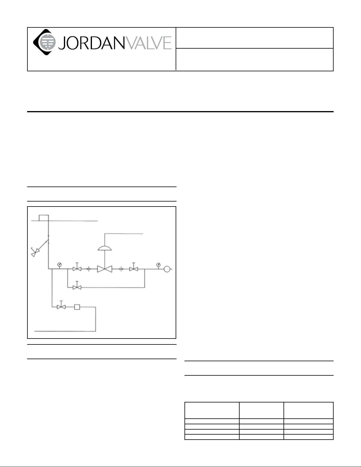
Ideal Installation
Main Line
Control Air
3
4
1
Condensate Return Line
7
1
1
6
7
2
1 Shut-off Valve
2 Jordan Control Valve
3 Strainer & Drain Valve
4 Pressure Gauge
5 Relief Valve
6 Steam Trap
7 Pipe Union
1
4
5
R
Preferred Installation
Installation & Maintenance Instructions for
Mark 701/702/707/711 Control Valves
foreign matter. A 0.033 perforated screen is usually
suitable. Line strainers are available from Jordan Valve.
For best control, 3’0” straight sections of pipe should 4.
be installed on either side of the valve.
In preparing threaded pipe connections, care should 5.
be exercised to prevent pipe-sealing compound
from getting into the pipelines. Pipe sealing compound should be used sparingly, leaving the two
end threads clean. Jordan uses, and recommends,
thread sealer Teon ribbon.
The ow arrow on the valve body must be pointed 6.
in the direction of ow. Ideally, the valve should be
installed in the highest horizontal line of piping to
provide drainage for inlet and outlet piping, to prevent water hammer, and to obtain faster response.
If possible, install a relief valve downstream from the 7.
valve. Set at 15 psi above the control point of the
valve.
In hot vapor lines, upstream and downstream pip-8.
ing near the valve should be insulated to minimize
condensation.
In gas service, if the control pressure (downstream) 9.
is 25% of the inlet pressure or less, expand the outlet piping at least one pipe size. A standard tapered
expander connected to the outlet of the valve is
recommended.
Where surges are severe, a piping accumulator is 10.
recommended.
On steam control applications, install a steam trap 11.
with sufcient capacity to drain the coil or condenser. Be sure to have a good fall to the trap, and no
back pressure. Best control is maintained if the coil
or condenser is kept dry.
To protect the valve from grit, scale, thread chips, 1.
and other foreign matter, all pipe lines and piping
components should be blown out and thoroughly
cleaned before the valve is installed.
Shutoff valves, pressure gauges, and bypass piping 2.
should be installed as indicated in the Ideal Installation Schematic to provide easier adjustment, opera-
tion, and testing.
A line strainer should be installed on the inlet side of 3.
the regulator to protect it from grit, scale and other
Start-Up
Be sure that the action of the control valve and of 1.
the controller are such as to give the desired results.
If an increase in
pressure or temperature
must:
close valve air-to-close (direct) direct
close valve air-to-open (reverse) reverse
open valve air-to-close (direct) reverse
open valve air-to-open (reverse) direct
And the action of
the valve is:
Then the action of the
controller must be:
Page 2

The control valve has been pre-set by Jordan Valve. 2.
However, ner adjustments may be required to
compensate for pressure drop conditions of the application.
With the inlet, outlet, and bypass shutoff valves 3.
closed, and no pressure in the downstream line, fully
open the outlet shut off valve. Increase ow gradually by slowly opening the inlet shutoff valve. Do
not fully open the inlet valve until you are sure that
the controller and control valve have control of the
system. Usually, the handwheel on the inlet valve will
turn freely when this point is reached.
To shut off the line uid, close the inlet shut-off valve 4.
rst, then the outlet shut-off valves.
Body and cap bolts should be retightened per 5.
torque procedures after valve reaches operating
temperature.
Valve Maintenance
Caution: Make certain that there is no pressure in the
valve before loosening any ttings or joints. The following steps are recommended.
side as the “<” on the body and cap.
Now, remove the disc (6) and disc guide (4), placing 4.
the disc on the bench with the lapped surface up.
Fingertip pressure should be sufcient to remove
these parts.
It is critical that the disc pin not be rotated
when disassembling, cleaning, or reassembling, since this affects the stroke adjustment.
Clean all parts of the body and cap with a good 5.
quality solvent. The disc and plate can then be
cleaned. Place a 4/0 polish cloth or jeweler’s cloth
on a smooth, at surface and polish the lapped
surfaces. If the parts are badly scarred, do not attempt to relap them, but return them to the factory
for repair or replacement. If the parts are not scarred
too deeply, they can be repaired at minimal cost.
A 0.005 feeler gauge should be used to check the 6.
clearance between the disc and the disc guides.
If the clearance is less than 0.005”, clean the disc
guides with a smooth le.
For Reassembly
Close inlet shutoff valve.1.
Allow pressure to bleed off through downstream 2.
piping. Do not attempt to reverse the valve by bleeding pressure from the upstream side of the valve.
When the pressure gauges indicate that all pressure 3.
has been removed from the system, close the outlet
shutoff valve, and the valve may be serviced.
Note: refer to the drawing at the end of this document for description and proper orientation of parts.
Valve Seats
Follow instructions under Maintenance section to 1.
remove valve from line.
Disassemble the valve only as far as necessary to do 2.
the required work. See Valve Disassembly section.
When replacing seats it is recommended by Jordan 3.
Valve that the packing be replaced if the valve is
older than one year. Follow the instructions under
Packing.
Valve Disassembly/Reassembly
1/2” to 1-1/4” Sizes
To remove the control valve from the line, follow the 1.
instructions under MAINTENANCE.
Secure the body hex in the vise. Remove the cap 2.
screws (3) and lift the cap (2) straight up.
Next, remove the plate (5) and place it on the bench 3.
with the lapped surface up. You will notice that there
is also a locating pin that aligns the plate with the
disc guide. This locating pin should be on the same
Place the disc guide (4) in the body bore with the lo-7.
cating pin on the same side as the “<” on the body.
Place the disc (6) in the aperture of the disc guided 8.
(4) with the arrow pointing to the index pin hole and
engage the disc pin (8).
In placing the plate (5) in the body (1), notice that 9.
the index pin hole in the lapped surface of the plate
engages the index pin of the disc guide (4).
Replace the cap (2).10.
Tighten the cap screws (3) uniformly, being cautious 11.
not to apply too much torque. See Torque Requirements.
1-1/2” & 2” Sizes
To remove the control valve from the line, follow 1.
instructions under MAINTENANCE.
Secure the body hex in a vise. Remove the cap bolts 2.
(3) and lift the cap (2) straight up.
Remove the pressure ring (4A). Remove the disc 3.
(6) and plate (5) assembly by lifting the assembly
straight up from the body. Place the assembly on the
bench with the disc up.
It is critical that the disc pin not be rotated
when disassembling, cleaning, or reassembling, since this affects the stroke adjustment.
Clean the body and cap bores with a good quality 4.
solvent.
To clean the disc and plate, remove the guide 5.
screws. Place a 4/0 polish cloth or jeweler’s cloth on
a smooth, at surface and polish the lapped surfaces. If the parts are badly scarred, do not attempt to
Page 3

relap them, but return them to the factory for repair
or replacement. If the parts are not scarred too
deeply, they can be repaired at minimal cost.
For Reassembly:
Place the disc (6) on the plate (5) and replace the 6.
guide screws (7). Tighten the guide screws but do
not allow the screws to bind the disc against the
plate.
Replace the disc and plate assembly and the pres-7.
sure ring. Make sure that the disc pin engages the
disc and that the plate seats solidly against the plate
seat in the body.
Replace the cap and cap bolts, and tighten uni-8.
formly, being careful not to torque excessively. See
Torque Requirements.
2-1/2” & 6” Sizes
To remove the control valve from the line, follow 1.
instructions under MAINTENANCE.
Remove body cap bolts (3) and pull the cap (2) from 2.
the body (1). Notice that the cap has an internal
vertical web on which the disc spring (7A) is located.
Check the condition of the disc trap.
Remove the disc (6) and place it on the bench with 3.
the lapped surface facing up.
Remove the plate (5) and place it on the bench with 4.
the lapped surface up. Finger pressure should be
sufcient to remove the plate. If not, strike gently
from the rear, using a blunt, nonmetallic object. Notice that the plate is positioned in the body by two
index pins (7B). These pins are secured in the body
and extend through the plate gasket (40) and into
the holes in the plate. These pins prevent the plate
from rotating in the body.
It is critical that the disc pin not be rotated
when disassembling, cleaning, or reassembling, since this affects the stroke adjustment.
Clean all of the parts of the body and cap with sol-5.
vent. The disc and plate then may be cleaned. Place
a piece of 4/0 polishing cloth or jewelers cloth on
a smooth, at surface such as a surface plate, and
polish the lapped surfaces of the disc, plate and
disc guide using a “gure 8” motion. If the parts are
scarred, do not attempt to relap them, but return
them to Jordan Valve for repair or replacement. If the
seats are not scarred deeply, they can be repaired at
a nominal cost.
Reassemble in reverse order.6.
Install the cap screws and tighten uniformly. See 7.
Torque Requirements.
Stem, Disc Pin & Packing Replacement
Remove disc (6) and plate (5) following the proce-1.
dure outlined under Valve Seats.
Loosen stem connector nut (20) and bolt (19) and 2.
remove connector (18).
Back out the four allen head yoke screws (23) (1/2” 3.
- 2” sizes) or four yoke bolts (42) (2-1/2” - 6” sizes)
which will allow the body to be separated from the
yoke.
Remove the packing ange nuts (17) and the pack-4.
ing ange (15).
Loosen the stem locknut (9) and rotate the disc pin 5.
(8) counter-clockwise, pulling the valve stem (10)
upward while doing so.
When pulling the stem completely out of the body, 6.
you will remove most of the packing assembly (11)
also. The remaining parts of the packing assembly
can be “shed” out with a small screw driver.
Clean the packing bore in the body with solvent and 7.
blow dry.
The disc pin may be removed through the body 8.
bore.
Clean the stem and disc pin with solvent if they are 9.
to be reused.
Reassemble the disc pin (8), stem (10) and lock nut 10.
(9) in the valve body as they originally were.
Replace the packing spring (12) and packing retainer 11.
(13) in the packing bore.
Reassemble the new packing (11) on the stem with 12.
the open part of the “V” downward (^). There will be
a at on the top and bottom. Place the packing follower (14) on top of the packing.
Gently push the packing into the packing bore and 13.
place the packing ange (15) on the stem and over
the packing studs (16).
Put on the ange nuts (17) and tighten them partially. 14.
At this point it is recommended that you gently move
the stem up and down three or four times to align
the assembly. Tighten the ange nuts until the packing follower bottoms out on the top of the body.
Replace actuator in reverse order. Reassemble the 15.
valve by inserting seats as outlined in Valve Assembly Section for the size valve you are working with.
Then follow the instructions for Seat Alignment.
Actuator / Diaphragm
Caution: do not apply more than 50 psi to actuator
The valve need not be removed from the line, but before
performing any maintenance on the actuator, shut off
the control air supply and remove the line from the
actuator.
-3-
Page 4

Actuator Disassembly
Loosen the stem connector bolt (20) and nut (19), 1.
and remove the stem connector (18).
Remove the actuator assembly from the valve by 2.
removing the four adapter plate bolts (22) and lifting
the actuator off the yoke (21).
Release the spring compression by threading the 3.
actuator stem (24) out of actuator, being careful not
to loosen the actuator stem locknut (44) or move the
stem adapter (43) (on 1/2” to 2” sizes).
Remove the actuator case bolts (29) and nuts (30) 4.
and lift the upper actuator case (28) off of the lower
actuator case.
Lift the diaphragm assembly out of the actuator case 5.
(27).
Loosen and remove the two actuator bolt locknuts 6.
(36). Remove the diaphragm plate (33) and diaphragm (34) from the actuator.
Clean all parts with a good quality solvent. Remove 7.
encrusted material with crocus or very ne aluminum oxide cloth. Inspect all parts for excessive wear
and/or damage and replace worn or damaged parts.
Use only Jordan Valve Replacement Parts. The use
of other than genuine Jordan Valve parts may impair
their ability to function properly.
Actuator Reassembly
Assemble the diaphragm stops (32), diaphragm (34), 1.
and diaphragm plate (33) to the actuator bolt (35).
Assemble and tighten the two actuator bolt lock nuts
(36) making sure that they are locked together.
Place the diaphragm assembly (from step 1) on the 2.
upper actuator case (28) with the diaphragm plate
(33) up. Place the springs (37) on the diaphragm
plate so they nest the formed bosses. Assemble the
lower case (27).
Replace four of the actuator case bolts (29) and 3.
nuts (30) at 90° and tighten nger-tight. Thread the
actuator stem (24) (with the stem adapter (42) for
the 1/2” to 2” sizes) onto the actuator bolt (35) until
the shoulder on the stem connects the adapter plate
and a slight amount for spring compression can be
felt.
Reassemble the actuator assembly to the yoke using 4.
the four adapter plate bolts (22).
Reconnect the actuator stem (24) to the valve stem 5.
(10) using the stem connector (18) and its bolt (19)
and nut (20).
Adjust the spring preload as shown in Spring Adjust-6.
ment.
Valve Stroke Adjustment
1/2” to 2” sizes:1. loosen the stem connector nut
(20), only enough to allow the stem adapter (43) to
rotate. Do not remove the stem connector (18).
Proper positioning of the valve stem and the stem
adapter (43) must be maintained while adjusting the
seats.
2-1/2” to 6” sizes:2. remove the seats as outlined
under Valve Seats and loosen the disc pin locknut
(9). Put the seats back in place. Loosen the stem connector nut (20) only enough to allow the stem (19)
to rotate. Do not remove the stem connector (18).
Proper positioning of the valve stem (10) and actuator stem (24) must be maintained while adjusting the
seats.
Direct Acting (air-to-close) Valves:3. thread the actuator stem (24) onto the actuator bolts (35) until the
springs are slightly compressed. This insures that the
actuator stem is slightly compressed. This insures that
the actuator stem is in its fully upward position. To
conrm that the actuator stem is fully stroked down,
check that it cannot be rotated easily with a wrench.
Reverse Acting (air-to-open) Valves:4. apply an air
pressure to the actuator of approximately 5 psi
above the maximum range pressure (i.e. 20 psi for
3-15 psi range). This should stroke the actuator stem
fully down. To conrm that the actuator stem is fully
stroked down, check that it cannot be rotated easily
without a wrench.
1/2” to 2” sizes:5. the orices in the disc (6) and plate
(5) must be perfectly aligned in the open position. If
they are not, loosen the actuator stem locknut (44)
and rotate the stem adapter (43), which moves the
disc pin (8) and disc (6) up or down on the plate.
2-1/2” to 6” sizes:6. the orices in the disc (6) and
plate (5) must be perfectly aligned in the open position. If they are not, adjust the alignment of the orices by rotating the valve stem (10), which moves the
disc pin (8) and disc (6) up or down on the plate (5).
1/2” to 2” sizes:7. after proper alignment has been
achieved, tighten the locknut (44) against the end of
the actuator stem (43). Recheck the seat adjustment.
2-1/2” to 6” sizes:8. after proper alignment has been
achieved, remove the seat assembly and carefully
tighten the disc pin locknut (9), taking care not to
rotate the disc pin (8). Replace the seats and recheck
the seat alignment.
Adjust the spring preload as shown in 9. Spring Adjust-
ment.
Spring Adjustment
Note: Actuators arranged for 3-15 range, Reverse Air-ToOpen: Jordan control valves rated 3-15 psig, ATO, are
bench set at the factory at 5-17 psig. Please insure that
any I/P utilized with this control valve is capable of 17 psig
output to insure full valve travel. If desired, the range may
be changed to suit your needs by following the instructions below.
The signal range (3-15 psi or other) is preset by Jordan
Valve. When the valve is installed, however, this range
may shift slightly due to pressure drops across the valve.
-4-
Page 5

Additionally, preload adjustments may be required after
one of the previous maintenance procedures.
Changing Valve Action
Remove the air signal line from the actuator and 1.
replace with a pressure gauge and an air regulator.
Loosen, but do not remove, the stem connector bolt 2.
(19) and nut (20).
Adjust the actuator air pressure to just below the 3.
starting point of the range and rotate the actuator
stem (24) until the stem just starts to move. Continue
to rotate the actuator stem about one-half turn. Remove the air pressure. Increase the air pressure and
check the pressure at which the valve just starts to
move. Repeat actuator stem adjustment if necessary
and again check pressure at which the stem starts to
move.
After the preload has been properly adjusted, 4.
tighten the stem connector bolt (19) and nut (20)
and reattach the control air line.
Troubleshooting
Erratic Control
Oversizing causes cycling or hunting – recalculate •
size required.
Steam traps downstream may need reconditioning.•
Excessive foreign matter may be lodged in seats.•
Valve stroke may be out of adjustment.•
Valve disc may not be moving freely.•
The action of a sliding gate valve can be changed from
direct to reverse, or vice-versa, by rotating the disc, plate
and cap 180°. Check valve stroke and orice alignment
and readjust, if required, as shown under Valve Stroke
Adjustment.
Torque Requirements
5
3
2
6 bolts (or multiples) 8 bolts (or multiples)
Valve Size CI, DI, BRZ CS, SST
1/2” & 3/4” 110 in-lbs 200 in-lbs
1” & 1-1/4” 120 in-lbs 200 in-lbs
1-1/2” & 2” 140 in-lbs 200 in-lbs
2-1/2” & 6” 1080 in-lbs 1080 in-lbs
1
4
6
Torque for Bolts Connecting Cap to Body
3
7
5
2
1
6
8
4
Will not operate
Diaphragm ruptured and needs replacement•
Spring(s) broken and needs replacement•
Improper spring setting (reset).•
-5-
Page 6

Illustration & Part List
1/2” to 1-1/2” Sizes (See seat arrangement at lower portion of drawing for 1-1/2” & 2”)
44
43
20
17
15
23
14
33
26
34
6
2
31
35
1/2” – 1-1/4”
3
5
(701)
32
36
14
28 37
8
29
30
27
25
24
22
19
18
16
21
11
13
12
10
50
51
54
53
52
MK701/702
9
1-1/2” – 2”
(701/702)
6
7
4A
5
Item Description Item Description Item Description
1 Body 15 Packing Flange 30 Actuator Case Nut
2 Cap 16 Packing Stud 31 Seal Washer
3 Bolt (Body - Cap) 17 Packing Nut 32 Diaphragm Stop
4 Disc Guide (1/2” – 1-1/4”) 18 Stem Connector 33 Diaphragm Plate
4A Pressure Ring (1-1/2” – 2”) 19 Stem Connector Bolt 34 Diaphragm
5 Plate 20 Stem Connector Nut 35 Actuator Bolt
6 Disc 21 Yoke 36 Actuator Bolt Locknut
7 Guide Screw (1-1/2” – 2”) 22 Adapter Plate Bolt 37 Spring
8 DIsc Pin 23 Yoke Screw 43 Stem Adapter
9 Stem Locknut 24 Actuator Stem 44 Actuator Stem Locknut
10 Stem 25 Adapter Plate 50 Positioner Adapter Ring
11 Packing 26 Adapter Plate Actuator Bolt 51 Positioner Screw
12 Packing Spring 27 Lower Actuator Case 52 Positioner Gasket
13 Packing Retainer 28 Upper Actuator Case 53 Positioner Spring
14 Packing Follower 29 Actuator Case Bolt 54 Positioner
-6-
Page 7

Illustration & Part List
2-1/2” – 6” Sizes
2
22
16
17
15
41
7B
27
25
20
3
28
34
33
32
35
31
36
37
29
30
26
Item Description
21
1 Body
24
18
19
10
42
2 Cap
3 Cap Bolt
5 Plate
6 Disc
7A Disc Spring
7B Disc Guide Pin
8 Disc Pin
9 Stem Locknut
14
11
13
10 Valve Stem
11 Packing
12 Packing Spring
13 Packing Retainer
14 Packing Follower
12
15 Packing Flange
16 Packing Stud
9
17 Packing Nut
18 Stem Connector
8
19 Stem Connector Bolt
20 Stem Connector Nut
21 Yoke
22 Adapter Plate Bolt
24 Actuator Stem
1
25 Adapter Plate
26 Bolt (Adapter Plate - Actuator)
27 Lower Actuator Case
28 Upper Actuator Case
29 Actuator Case Bolt
30 Actuator Case Nut
39
67A
5
40
38
31 Seal Washer
32 Diaphragm Stop
33 Diaphragm Plate
34 Diaphragm
35 Actuator Bolt
36 Actuator Bolt Locknuts
37 Spring
38 Pipe Plug
39 Stem Bushing
40 Gasket (Body-Plate)
41 Gasket (Cap-Plate)
42 Yoke Bolt
Bulletin IM-MK701/702-1208
3170 Wasson Road • Cincinnati, OH 45209 USA
Phone 513-533-5600 • Fax 513-871-0105
info@richardsind.com • www.jordanvalve.com
 Loading...