

Page 1
Mark 688 Series
3170 Wasson Road • Cincinnati, OH 45209 USA
Phone 513-533-5600 • Fax 513-871-0105
info@richardsind.com • www.jordanvalve.com
Mark 688 Piloted Soft Seat Regulators
Installation Instructions for
Warning: Jordan Valve Pressure Regulators must only be used, installed and repaired in accordance with these Installation & Maintenance Instructions. Observe all applicable public and company codes and regulations. In the event
of leakage or other malfunction, call a qualified service person; continued operation may cause system failure or a
general hazard. Before servicing any valve, disconnect, shut off, or bypass all pressurized fluid. Before disassembling
a valve, be sure to release all spring tension.
Please read these instructions carefully!
and be thoroughly familiar with API 2000, Standard
Information for Tank Blanketing Regulator Selection
Your Jordan Valve product will provide you with long,
trouble-free service if it is correctly installed and main-
before installing and attempting to operate this
product.
tained. Spending a few minutes now reading these instructions can save hours of trouble and downtime later.
Control Line
When making repairs, use only genuine Jordan Valve
parts, available for immediate shipment from the factory.
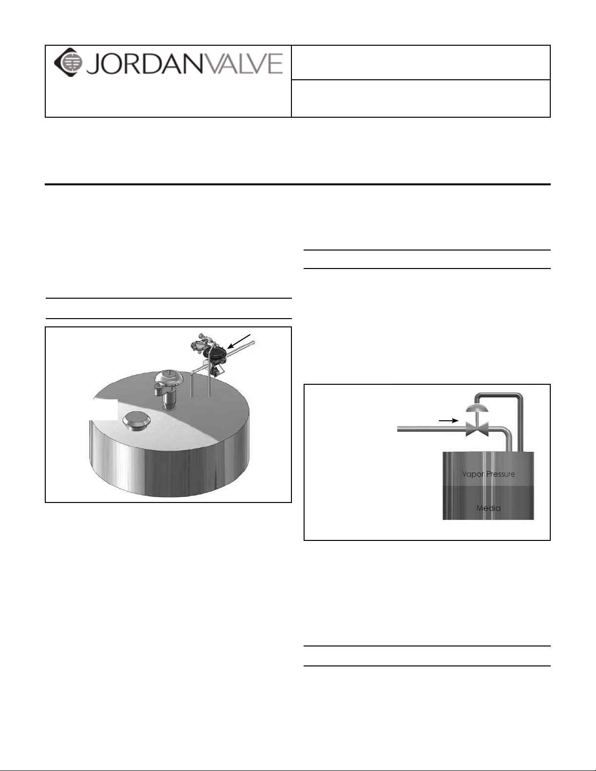
Ideal Installation
A control line must be installed as follows:
1. Connect one end of a ¾” pipe to the fitting on top
of the main valve actuator.
Gas Supply
2. Connect the other end to an appropriate fitting on
the tank.
Conservation Vent
Blanketing
Valve
3. DO NOT locate the control line tap in any location
where turbulence or abnormal velocities may occur.
Emergency
Pressure Vent
Control Line
1. To protect the valve from grit, scale, thread chips
and other foreign matter, ALL pipelines and piping
Control line should
slope downward toward
the tank to prevent
Condensation buildup.
1. Make the control line as short
and straight as possible.
2. Connect the control line to
the point where the pressure
is to be controlled.
3. Increase 1 pipe size for every
10 feet of control line, with
setpoints less than 5" w.c.
(0,012 bar).
Blanketing Gas
Control line
components should be blown out and thoroughly
cleaned before the installation process begins.
2. Shutoff valves, pressure gauges and by-pass piping are optional, and if installed should be in accordance with all applicable codes, standards, and
practices. They are recommended to provide easier
4. The control line should be sloped away from the
valve.
5. Install a pressure gauge to measure pressure in the
tank itself, not in the outlet piping or the control line
to aid in setting the valve.
adjustment, operation, and testing.
3. The flow arrow on the valve body must be pointed
in the direction of flow. Ideally, the valve should be
installed in the highest horizontal line of piping.
Control Line Piping Recommendation
4. If possible, install a relief valve downstream from
the valve. Set at slightly above the control point of
the valve but below the maximum safety limit for
the tank.
5. It is strongly recommended that the installer read
Keep the regulator as close to the tank as possible
and as high as possible.
Minimize the length of the downstream pipe com-
ing from the valve.
Page 2

NEVER reduce the pipe size on the valve outlet to
the tank. This line must always be as large as the
valve size, or one pipe size larger to assure it does
not act as a restriction.
Any downstream isolation valve after the regulator
must be a full port type. The isolation valve cannot
act as a restriction.
The sensing line must be a minimum of 3/4" pipe.
A sensing line isolation valve is recommended.
Again, must be full ported.
Slope the sensing line to the sensing port on the
tank.
Keep the sensing line as short and straight as pos-
sible.
For each 10 feet of sensing line, increase the line
size by one pipe diameter. (Especially important on
the blanket pressures of less than 5 inches of water
column).
Keep the sensing port on the tank as far removed
as possible from the downstream pipe outlet going
into the tank.
Start-Up
With the inlet, outlet, and bypass shutoff valves closed,
and no pressure in the downstream line:
1. Slowly open the inlet valve just enough to start
flow through the valve. Observe the tank pressure
gauge. Increase the downstream pressure slowly
by gradually opening the inlet valve.
2. Do not fully open the inlet valve until you are sure
that the regulator has control of the system. Usually, the handwheel on the inlet valve will turn freely
when this is achieved.
3. To change the controlled pressure, adjust the
controlled pressure supplied to the top of the diaphragm.
The next step is to determine what could cause the
trouble. The third step is to locate and remedy the cause
by the process of elimination. Make no assumptions and
check the easy ones first. The guide below lists the controlled pressure action, common causes and procedure
for checking each cause.
Controlled pressure action UNDER PRESSURE:
Valve undersized for application. Check capacity
required and valve capacity.
Line strainer screen clogged. Blow down strainers
or visually check that they are clear.
Incorrect setting on range spring. Vary the setting
and check response.
Main valve diaphragm or balance diaphragm rup-
tured. See action on valve maintenance.
Malfunction of other piping components. Check
for leaking safety valves, inadvertently opened or
closed valves.
Controlled pressure action OVER PRESSURE:
Incorrect setting on range spring. Vary the setting
and check response.
Main valve seats leaking. Close inlet shut-off valve,
allow downstream pressure to bleed off, close outlet valve and remove loading pressure tubing. Back
out adjusting screw on valve until free. Crack open
inlet shut-off valve - if the fluid issues from the main
valve port, the main valve seats are leaking.
By-pass shut-off leaking. During period of leakage
close outlet shut-off valve, observe downstream
pressure gauge.
Controlled Pressure Fluctuates:
Valve oversized. Check capacity required and valve
capacity.
Main Valve
Trouble Shooting
The first step in troubleshooting a piloted pressure regulator is to classify the action of the controlled pressure
into one of the following categories:
A. Under Pressure: Controlled pressure too low; not
enough flow or no flow through valve.
B. Over Pressure: Valve will not close or controlled
pressure increases after valve closes.
C. Pressure Fluctuates: Controlled pressure rises and
falls, will not settle out under low loads.
Note: All work to the main valve can be accomplished
in-line. The only reason to remove the valve is if
the location makes it too difficult to work on the
regulator.
Main Valve Diaphragm
1. Remove pilot valve tubing.
2. Remove the control line to the upper case.
3. Remove the actuator bolts (24) and nuts from the
upper and lower actuator cases. Important - leave
two opposing bolts assembled.
Page 3

4. Use caution when removing the final two bolts. The
upper case is spring-loaded by the internal return
spring (21).
5. Remove the return springs from the diaphragm plate
(21).
6. Remove the valve stem bolt (31) and seal washer
(27) from the diaphragm assembly.
7. Remove the seal washer (33) from the center of the
diaphragm plate.
8. Lift off the diaphragm plate (20) and remove the
diaphragm (19).
9. Inspect and replace as required by reversing the
above steps.
10. When re-assembling, it is necessary to balance the
lower support plate (11) on top of the valve plug/
stem assembly (8). Make sure the valve stem bolt
engages all parts in the diaphragm assembly before
tightening. Use a new seal washer (17).
11. To tighten the valve stem bolt, hold the outside of
the diaphragm plate to prevent the assembly from
turning while tightening the bolt.
12. Make sure to locate the return springs on the
stamped guides in the diaphragm plate before assembling the upper case.
16. Assemble the plug o-ring (30) and seal (27) to the
plug groove. Place an additional amount of grease
on the outside of the seal and carefully insert the
plug / stem into the cage (9) being careful not to
damage the o-ring.
17. Place the cage and plug / stem on top of the seat
assembly in the body.
18. Place a new spacer (12) on top of the cage.
19. Insert the bonnet (2) over the stem and onto the
body.
20. Assemble the 4 body bolts (3) using an even
cross-torquing method. Torque to 75 ft-lbs.
21. Place the packing spring (16), retainer (15), new set
of packing (14), and the packing follower (15) into
the packing bore of the bonnet. Lubricate each
piece of packing upon installation.
22. Place the lower actuator assembly over the bonnet.
Make certain the port on the lower case is oriented to the same side as when it was removed, and
is 90° to the flow direction.
23. Secure the actuator nut (7) to the lower case using
a minimum of 100 ft-lbs or torque.
24. Follow the steps outlined above under “Main Valve
Diaphragm” to finish assembling the actuator.
Main Valve Seats
1. Remove diaphragm as listed above.
2. Remove the actuator nut (7) from the lower case.
3. Lift the lower case assembly off of the bonnet.
4. Remove the 4 body bolts (3).
5. Lift off the bonnet assembly (2) from the main valve
plug / stem assembly (8).
6. Remove the plug / stem and cage (9) from the body
bore. Note - the cage will normally come out with
the plug.
7. Remove the seat assembly and o-ring (25) from the
bore of the body.
8. Separate the plug / stem from the cage.
9. Remove plug -O-ring (30) and seal (27).
10. Clean all parts with a light solvent.
11. Replace o-ring numbers (25), (29), (30), & seal (27).
12. Use a light grease, such as Dow Corning #4 to lubricate all o-rings prior to re-assembly.
13. Place the seat o-ring (30) into the body bore, pushing it all the way into the corners of the bore.
14. Place the seat ring (13) on top of the o-ring.
15. Insert a new soft seat (10) into the groove on the
seat ring.
Page 4
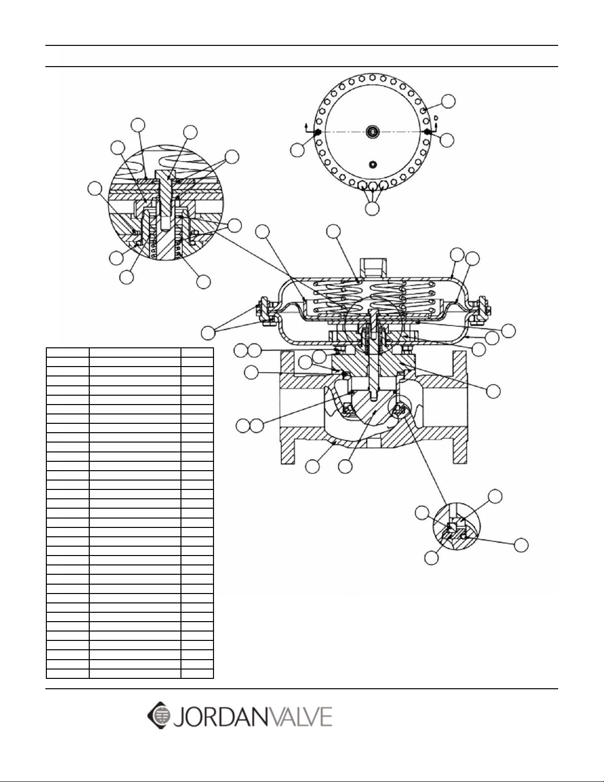
Parts List
23
33
31
7
28
26
14
Detail M
16
24
Item No. Description Quantity
1 Body 1
2 Bonnet 1
3 HHCS, 1/2-13 x 1-1/4" 4
4 Lower Actuator Case 1
5 Mounting Plate 1
6 HHCS, 5/16-18 x 3/4" 6
7 Ring Nut 1
8 Plug 1
9 Cage 1
10 Soft Seat Insert 1
11 Backing Plate 1
12 Compressor 1
13 Seat 1
14 Pacing 1
15 Packing Follower/Retainer 2
16 Packing Spring 1
17 Threadseal 8
18 Upper Actuator Case 1
19 Diaphragm 1
20 Diaphragm Plate 1
21 Return Spring 6
22 HHCS, 3/8-16 x 1-1/2" 3
23 HHCS, 3/8-16 x 1" 27
24 Hex Nut, 3/8-16 32
25 O-Ring #345 1
26 O-Ring #219 1
27 Plug Seal 1
28 O-Ring #222 1
29 O-Ring #154 1
30 O-Ring #138 1
31 HHCS, 5/16-18 x 1" 1
32 HHCS, 3/8-16 x 1-3/4" 2
33 Seal Washer 1
45 3
17
15
17 6
12
27
30
20
32
3
29
1
Section D-D
Scale 1:2
21
32
22
18
19
11
4
4
5
2
8
9
10
25
13
Detail L
Bulletin IM-MK688-0113
3170 Wasson Road • Cincinnati, OH 45209 USA
Phone 513-533-5600 • Fax 513-871-0105
info@richardsind.com • www.jordanvalve.com
Page 5

I & M Mark 608P
3170 Wasson Road • Cincinnati, OH 45209 USA
Phone 513-533-5600 • Fax 513-871-0105
info@richardsind.com • www.jordanvalve.com
Warning: Jordan Valve Pressure Regulators must only be used, installed and repaired in accordance with these Installation & Maintenance Instructions. Observe all applicable public and company codes and regulations. In the event
of leakage or other malfunction, call a qualified service person; continued operation may cause system failure or a
general hazard. Before servicing any valve, disconnect, shut off, or bypass all pressurized fluid. Before disassembling
a valve, be sure to release all spring tension.
Please read these instructions carefully!
Your Jordan Valve product will provide you with long,
trouble-free service if it is correctly installed and maintained. Spending a few minutes now reading these instructions can save hours of trouble and downtime later.
When making repairs, use only genuine Jordan Valve
parts, available for immediate shipment from the factory.
A. DIAPHRAGM OR GASKET REPLACEMENT
1. Remove all pressure from the line as outlined under
WARNING.
2. Remove the compression of the adjusting spring
(47) by rotating the adjusting screw (59) counterclockwise.
3. Loosen the spring housing bolts (48) and remove
spring housing.
IF DIAPHRAGM IS NOT BEING REPLACED,
SKIP STEPS 4 THRU 8.
4. Remove diaphragm subassembly by sliding it away
from the valve body to disengage the lever arm
(43).
5. Hold the lower diaphragm plate (57) and remove
the screw (61), separating the parts.
6. Clean the surfaces on the upper and lower
diaphragm plates that the diaphragm (46) seats
against. Clean and degrease the threads on the
lower diaphragm plate and the screw. (Degrease
with Loctite primer T.)
7. Assemble the upper and lower diaphragm
plates,diaphragm weight (60) to the new diaphragm
with the screw. (Apply a few drops of Loctite #290
to the screw threads to lock the parts together.) The
hole through the lower diaphragm plate must align
with any pair of opposite holes in the diaphragm
so that it will properly engage the lever when reassembled into the valve.
8. Clean the flange surface on the diaphragm housing
and reinstall the diaphragm subassembly onto the
lever arm.
Installation & Maintenance Instructions for
Mark 608P Low Pressure Pilot Regulators
9. Clean the flange surface on the spring housing and
install a new gasket. The gasket may be temporarily
held in place using a few dabs of grease.
10. Set the spring housing on top of the diaphragm
housing. Using a 6” long screwdriver, or similar
tool, reach through the spring housing and push
the diaphragm down to align the diaphragm holes
with the housings’ holes.
11. Drop the bolts into place and attach the lockwashers and nuts, finger-right.
12. Continue to push the diaphragm down and snugup the bolts.
13. Evenly torque the bolts as described in the Torque
Procedure Section.
14. Install the spring and adjusting screw. (Adjusting
spring per start-up instructions and replace cap.)
B. SEAT INSERT & PLUG REPLACEMENT
CAUTION: When replacing a plug or seat insert,
the lever must also be replaced to insure shutoff.
1. Remove all pressure from the line as outlined under
WARNING.
2. Loosen the union nut (40) and separate the actuator from the body.
3. Inspect the plug (41) and seat insert (39) to determine if replacement is required. Replace if there
are signs of wear or uneven seating on either part.
4. To replace the seat, simply unscrew it from the
body using a 7/8” thinwall socket wrench. Install
the new seat. An anti-seize compound applied to
the threads will aid in future removal.
5. To replace the plug, disassemble the actuator as
described in steps A2, A3, A4.
6. Remove the two screws (49) fastening the lever
arm bracket (42) to the diaphragm housing and lift
out the lever arm bracket with the lever.
7. Inspect aspirating hole in aspirator to be sure it is
clean. Remove and replace aspirator if stem guide
bores are worn. Remove and replace plug.
8. Remove the screws from the lever arm bracket and
clean the threads. Degrease with Loctite Primer T.
Also clean and degrease the tapped holes in the
diaphragm housing.
Page 6

9. Remove the pin (45), replace the lever and reassemble with the screws.
10. Apply a drop of Loctite #290 to each screw and
reinstall the lever arm bracket. Align the slot in the
plug’s stem with the new lever arm and tighten the
pivot bracket’s mounting screws. Check for free
movement. Be certain that there is a gasket (36)
between the guide flange and the diaphragm housing, and a gasket (37) in the body cavity where the
aspirator fits.
11. Re-attach body and actuator with the union nut (being careful to align the aspirator tube to the slot in
the body). Pull up hand-tight, then tighten further ¼
turn. (The union nut is 8-sided and may be used as
a guide).
12. If lever arm was replaced, apply 25-150 psi pressure through outlet. This will set linkage and prevent overpressure (in operation) from bending
the linkage and causing set point changes. Seat
leakage may be checked by observing any leakage
from inlet.
Ordering Spare Parts
Torque Procedure
1. Install all bolts hand-tight.
2. Torque the bolts in order of the bolt pattern to
approximately 75 in.-lbs.
3. Re-torque each bolt to 300 in.-lbs., using the same
bolt pattern as shown.
3
7
5
2
(or multiples)
1
6
8
4
8 bo l ts
Use only genuine Jordan Valve parts to keep your valve
in good working order. So that we can supply the parts,
which were designed for your valve, we must know exactly which product you are using. The only guarantee to
getting the correct replacement parts is to provide your
Jordan Representative with the valve serial number. This
number is located on the valve identification tag. If the
serial number is not available, the parts needed for your
valve might be determined using the following information: Model Number, Valve Body Size, Seat Material and
Cv Rating, Spring Range and Set Point, Trim Material, Part
Name - Number and Quantity.
NOTE: Any parts ordered without a valve serial number
that are found to be incorrect are subject to up to a
minimum 25% restock charge when returned.
-2-
Page 7

Item Description Qty.
34 Body 1
35 Lower Diaphragm Case with
Gauge Tap
36 Upper Basket 1
37 Lower Basket 1
38 Retaining Ring, Split 2
39 Seat Insert 1
40 Union 1
41 Plug 1
42 Bracket 1
43 Lever Arm 1
44 RHMS 10-32 x 3/4” 2
45 Dowel Pin 1
46 Diaphragm 1
47 Spring 1
48 HHCS 5/16-18 x 1-1/4” 6
49 Spring Housing 1
50 Cap 1
51 Screen 1
52 Pipe Plug 1
53 Lock Washer, 5/16 6
54 Hex Nut, 5/16-18 6
55 O-Ring, #016 1
56 Guide 1
57 Lower Diaphragm Plate 1
58 Upper Diaphragm Plate 1
59 Adj. Screw Assy 1
60 Diaphragm Plate 1
61 HHCS, 1/4-20 x 1/2” 1
1
Parts List
H
H
57
43
45
42
44
40
37
36
39
38
35
34
51
46
49
48 53
56
41
55
52
49
58
60
61
47
50
59
54
Bulletin IM-MK608P-0113
Section H:H
3170 Wasson Road • Cincinnati, OH 45209 USA
Phone 513-533-5600 • Fax 513-871-0105
info@richardsind.com • www.jordanvalve.com
Page 8

I & M Mark 68G Series
3170 Wasson Road • Cincinnati, OH 45209 USA
Phone 513-533-5600 • Fax 513-871-0105
info@richardsind.com • www.jordanvalve.com
Warning: Jordan Valve pressure regulators must only be used, installed and repaired in accordance with these
Installation & Maintenance Instructions. Observe all applicable public and company codes and regulations. In the
event of leakage or other malfunction, call a qualified service person; continued operation may cause system failure
or a general hazard. Before servicing any valve, disconnect, shut off, or bypass all pressurized fluid. Before disassembling a valve, be sure to release all spring tension.
Please read these instructions carefully!
Your Jordan Valve product will provide you with long,
trouble-free service if it is correctly installed and maintained. Spending a few minutes now reading these instructions can save hours of trouble and downtime later.
When making repairs, use only genuine Jordan Valve
parts, available for immediate shipment from the factory.
Ideal Installation
Main Steam Line
3
4
1
1
1
7
5
2
2
1 Shut off Valve
2 Pipe Union
3 Strainer and Drain Valve
4 Pressure Gauge
5 Jordan Regulator
6 Relief Valve
7 Steam Trap
4
1
6
R
Installation & Maintenance Instructions for
Mark 68G Pressure Regulators (1/4” – 2”)
two end threads clean. Jordan uses, and recommends, thread sealer Teflon ribbon.
4. A line strainer should be installed on the inlet side of
the regulator to protect it from grit, scale and other
foreign matter. A 0.033 perforated screen is usually
suitable. Line strainers are available from Jordan Valve.
5. Install the regulator in the highest horizontal line of
piping to provide drainage for inlet and outlet piping, to
prevent water hammer and to obtain faster regulation.
6. The flow arrow on the regulator body must be pointed
in the direction of flow. The regulator may be installed
vertically or horizontally without affecting its operation.
7. For best control, 3’0” straight sections of pipe should
be installed on either side of the valve.
8. In hot vapor lines, upstream and downstream piping
near the regulator should be insulated to minimize
condensation.
9. If possible, install a relief valve downstream from the
valve. Set at 15 psi above the control point of the
regulator.
10. Expand the outlet piping at least one pipe size if the
controlled pressure (downstream) is 25% of
the inlet pressure or less. A standard tapered expander connected to the outlet of the regulator is
recommended.
11. Where surges are severe, a piping accumulator is
recommended.
12. Operate the regulator within its rated pressure and
temperature.
Preferred Installation
1. To protect the valve from grit, scale, thread chips,
and other foreign matter, all pipe lines and piping
components should be blown out and thoroughly
cleaned before the valve is installed.
2. Shutoff valves, pressure gauges, and bypass piping
should be installed as indicated in the Ideal Installation Schematic to provide easier adjustment, operation, and testing.
3. In preparing threaded pipe connections, care
should be exercised to prevent pipe sealing compound from getting into the pipe lines. Pipe sealing
compound should be used sparingly, leaving the
Start-Up
1. Fully open the outlet shut-off valve.
2. Slowly open the inlet shut-off valve.
3. Slowly open and close outlet shut-off valve several
times. This fully strokes the valve to insure satisfactory operation.
4. With outlet shut-off valve open, slowly screw down
adjusting screw until the desired pressure is shown
on the outlet pressure gauge.
5. To change the controlled pressure, turn the adjusting screw clockwise to increase and counter-clockwise to decrease the pressure.
Page 9

Warning
Never substitute a longer length adjusting screw. Personal injury and damage to the valve may result.
Maintenance
WARNING
Be sure that there is no pressure in the valve before
loosening any fittings or joints. The following steps are
recommended:
1. Close the inlet shut-off valve.
2. Allow pressure to bleed off through the downstream
piping. Do not attempt to reverse the flow through
the valve by bleeding pressure from the upstream
side of the valve.
3. When downstream pressure gauge indicates no
pressure in the line, close the outlet shut-off valve.
Refer to the drawing for the proper orientation of the
parts and for proper nomenclature.
Troubleshooting
Erratic Control
• Oversizing causes cycling and hunting, and reduces
the rangeability of the regulator. Make certain that
your sizing is correct.
• Steam traps downstream may need attention.
• Safety valve may be jammed open, disrupting the
system. Repair as necessary.
• Excessive foreign matter on seat of plug (3)*.
Clean them. Inspect seating surface on plug for
deterioration.
• Valve stroke may not be moving freely. Check stem
(22), bushing (10) or cap bore (2).
Diaphragm Replacement
1. Remove all pressure from the line as outlined under
WARNING.
2. Remove the compression on the adjusting spring
(14) by rotating the adjusting screw (19) counterclockwise.
3. Remove the spring housing (17). Remove the spring
(14) and spring seat (15).
4. Lift the diaphragm assembly. This diaphragm assembly consists of the upper diaphragm plate (13),
diaphragm (11) and lower diaphragm plate (12).
5. Secure the upper diaphragm plate in a vise. Use a
spanner wrench on the lower diaphragm plate and
turn counter-clockwise to loosen and remove.
6. Remove the diaphragm, clean the parts and install
the new diaphragm in reverse order. Pull the parts
up tight when a metal diaphragm is used. When
elastomer diaphragms are used, clean and degrease
the threads, apply one drop of #290 Loctite to the
threads, and assemble. (Loctite Primer T may be
used to degrease). Thread the parts together, hand
tight, and then tighten 1/8 to 1/4 turn.
7. Clean the diaphragm seating surfaces on the spring
housing (17) and on the body (1).
8. Unscrew the cap (2) approximately two turns to
retract the stem. Place the diaphragm assembly,
spring, spring seat and ball bearing back onto the
valve body. (Metal diaphragms nest into the counterbore in the body).
9. Install spring housing. Tighten bolts (18) evenly per
chart.
10. Thread cap back into the body and pull snug.
Seat and Plug Replacement
Downstream pressure build-up
• Seats deteriorated. Inspect for foreign material between plug (3) and seat (9).
• Diaphragm (11) failed. Use metal seats for tighter shutoff. Consider elastomer seats.
Cannot Maintain Regulated Pressure
• Clogged strainer or lines.
• Inlet pressure low.
• Spring (14) set too low or broken.
• Valve is undersized for rated flow.
• System demand exceeds pump capacity.
* See back page for parts call-out.
1. Remove all pressure from the line as outlined in the
WARNING.
2. Turn the hex end on the cap (2) counter-clockwise
and remove it from the body. The plug (3) and return
spring (5) will come out with the cap.
3. Remove the seat (9) with a deep drive socket.
4. Inspect parts for wear and replace as required.
5. Clean all parts in the body and on the cap. Lightly
lubricate these surfaces.
6. Reassemble plug spring into cap and check for
smooth operation.
7. Install seat with a light coat of Teflon paste on the flat
seal area and anti-seize to the threads.
8. Install bottom cap onto the body with a light coat
of Teflon paste on the flat seal area and anti-seize
on the threads until it bottoms out on the body and
tighten.
-2-
Page 10

Torque Procedure
Torque Procedure
5
3
2
1
4
6
3
7
5
2
1
6
8
4
1. Install all bolts hand-tight.
2. Torque the bolts in order of the bolt pattern to a
value equal to 1/4 of the recommended torque
value.
3. Retorque each bolt to the recommended value using the same bolt pattern as shown.
Torque Chart for Spring Housing Bolts
Elastomer Diaphragm Metal Diaphragm
Bolt Size Torque Bolt Size Torque
5/16 200 in-lbs 5/16 300 in-lbs
3/8 300 in-lbs 3/8 300 in-lbs
Ordering Spare Parts
Use only genuine Jordan Valve parts to keep your valve
in good working order. So that we can supply the parts,
which were designed for your valve, we must know exactly
which product you are using. Please note the following
information on the valve’s nameplate:
• Serial Number
• Model and Size
• Body Material and End Connections
• Range
• Diaphragm and Seal Materials
-3-
Page 11

15
10
17
18
13
Cross Section View
1
19
20
1
21
1
14
1
11
12
3
9
22
Item Description Qty
1 Body 1
2 Bottom Cap 1
3 Plug Assembly 1
5 Return Spring 1
9 Orifice (Seat - Std Cv) 1
10 Bushing 1
11 Diaphragm 1
12 Lower Diaphragm Plate 1
13 Upper Diaphragm Plate 1
14 Range Spring 1
15 Spring Seat 1
17 Spring Housing 1
18 HHCS 10
19 Adjusting Screw 1
20 Jam Nut 1
21 Nameplate 1
22 Stem 1
23 Hart Seat 1
4
3
1
1
1
2
1
2
5
Notes:
1
These items may vary according to range feature
2
20 HHCS for MK68MP
3
Orifice (seat) is stellited on MK68MP only
4
Soft seat plug assembly - MK68G only
Bulletin IM-MK68G-0411
23
3
22
3
4
1
Optional
Soft Seat Trim/Plug Assembly
Seat Detail
3170 Wasson Road • Cincinnati, OH 45209 USA
Phone 513-533-5600 • Fax 513-871-0105
info@richardsind.com • www.jordanvalve.com
 Loading...