

Page 1
I & M Mark 62
3170 Wasson Road • Cincinnati, OH 45209 USA
Phone 513-533-5600 • Fax 513-871-0105
info@richardsind.com • www.jordanvalve.com
Warning: Jordan Valve pressure regulators must only be used, installed and repaired in accordance with these
Installation & Maintenance Instructions. Observe all applicable public and company codes and regulations. In the
event of leakage or other malfunction, call a qualied service person; continued operation may cause system failure
or a general hazard. Before servicing any valve, disconnect, shut off, or bypass all pressurized uid. Before disassembling a valve, be sure to release all spring tension.
Please read these instructions carefully!
Your Jordan Valve product will provide you with long,
trouble-free service if it is correctly installed and maintained. Spending a few minutes now reading these instructions can save hours of trouble and downtime later.
When making repairs, use only genuine Jordan Valve
parts, available for immediate shipment from the factory.
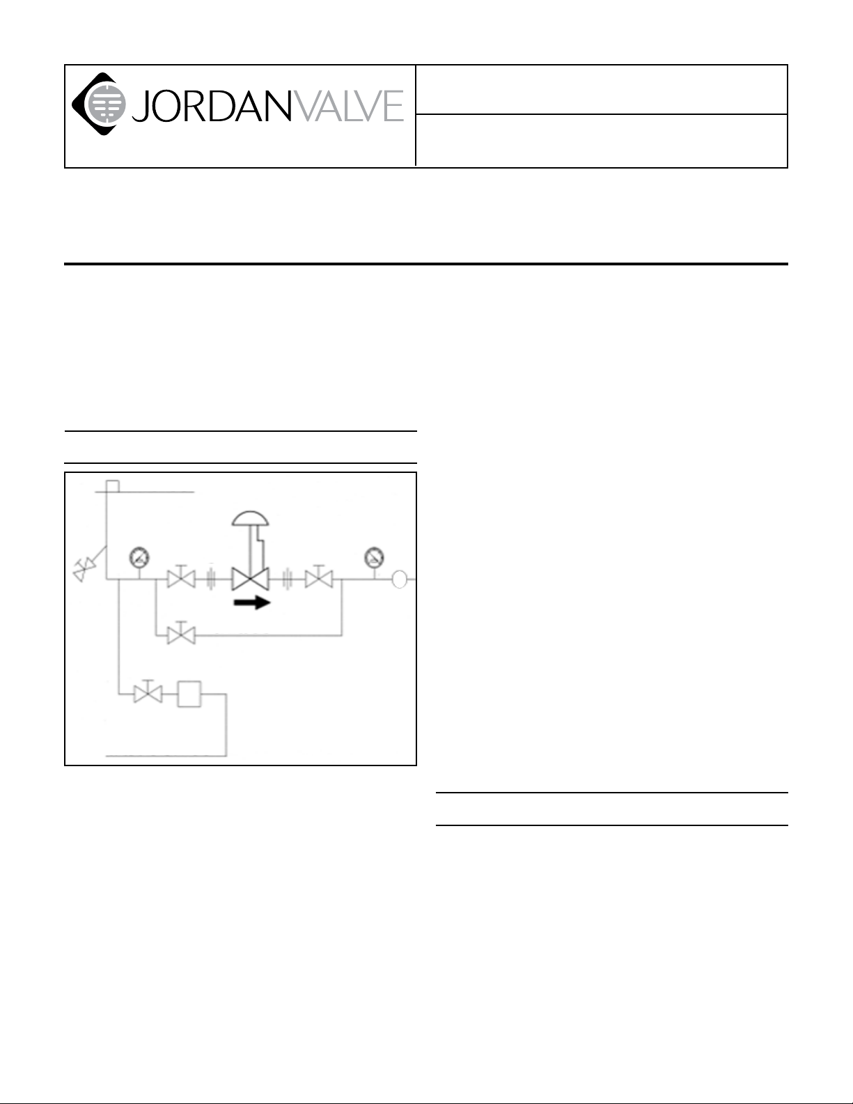
Ideal Installation
Main Steam Line
3
4
1 2
1
1
7
Condensate Return Line
To protect the valve from grit, scale, thread chips 1.
and other foreign matter, ALL pipelines and piping
components should be blown out and thoroughly
cleaned before the installation process begins.
Shutoff valves, pressure gauges, and by-pass pip-2.
ing should be installed as indicated in the diagram
above to provide easier adjustment, operation and
testing.
A line strainer should be installed on the inlet side 3.
of the valve to protect it from grit, scale, and other
foreign matter. A 0.033 perforated screen is usually
suitable for this purpose. Line strainers are available from Jordan Valve.
For best control, 3’ 0” straight sections of pipe 4.
should be installed on either side of the valve.
5
By-Pass Line
1. Shut off Valve
2. Pipe Union
3. Strainer and Drain Valve
4. Pressure Gauge
5. Jordan Regulator
6. Relief Valve
7. Steam Trap
1
2
4
Installation & Maintenance Instructions for Mark
62 Piloted Pressure Regulators 1/2” to 2” (PPRV)
In preparing threaded pipe connections, care 5.
should be exercised to prevent pipe-sealing compound from getting into pipelines. Pipe sealing
compound should be used sparingly, leaving the
two end threads clean. Jordan uses, and recommends, thread sealer Teon ribbon.
The ow arrow on the valve body must be pointed 6.
in the direction of the ow. Ideally the valve should
be installed in the highest horizontal line of piping to provide drainage for inlet and outlet piping,
to prevent water hammer, and to obtain faster response.
If possible, install a relief valve downstream from 7.
the valve. Set at 15 psi above the control point of
the valve.
In hot vapor lines, upstream and downstream pip-8.
6
R
ing near the valve should be insulated to minimize
condensation.
In gas service, expand the outlet piping at least 9.
one pipe size, if the control pressure (downstream)
is 25 percent of the inlet pressure or less. A standard tapered expander connected to the outlet of
the valve is recommended..
Where surges are severe, a piping accumulator is 10.
recommended.
On steam control applications, install a steam trap 11.
with sufcient capacity to drain the coil or condenser. Be sure to have a good fall to the trap, and no
backpressure. Best control is maintained if the coil
or condenser is kept dry.
Trouble Shooting
If you experience erratic control:
Oversizing causes cycling and hunting and reduces
the rangeability of the valve. Make certain that your
sizing is correct.
Steam traps downstream may need attention.
Safety valve may be jammed open.
Excessive foreign matter on seats.
Valve stroke out of adjustment. Check and readjust
if necessary.
Valve disc may not be moving freely. Check disc
guide clearance.
Page 2

If valve will not operate:
Diaphragm ruptured.
Adjusting Spring broken.
Improper Spring setting.
Upstream Pilot Tube Clogged.
Start Up
A minimum of 15 psi deferential is required be-1.
tween the upstream and downstream pressures for
operation of the PPRV.
Open the inlet shut-off valve.2.
Slowly open and close the outlet shut-off valve sev-3.
eral times to stroke the valve and insure satisfactory operation.
To change the controlled pressure, turn the adjust-4.
ing screw counterclockwise to decrease the pressure and clockwise to increase the pressure.
Body and cap bolts should be retightened per 5.
torque procedures after valve reaches operating
temperature.
Maintenance
Caution: Make certain that there in no pressure in the
valve before loosening any ttings or joints. The following steps are recommended:
Close the inlet shutoff valve.1.
Allow pressure to bleed off through the down-2.
stream piping. Do not attempt to reverse the ow
through the valve by bleeding pressure from the
upstream side of the valve.
When the pressure gauges indicate that all pres-3.
sure has been removed from the system, close the
outlet shutoff valve, and the valve may be serviced.
Note: refer to the drawing at the end of this document for description and proper orientation of parts.
Valve Seats
A. Disassembly
The sliding Gate Seats of Jordan Valves are lapped to
light band atness. Maintaining such tolerances is of
paramount importance for your assurance of excellent
control and tight shutoff. DO NOT use metallic objects
in removing the seats. Care in handling is imperative.
Follow the Maintenance Procedure and remove the 1.
valve from line.
Remove the inlet pilot tube and the outlet pilot 2.
tube.
Note the scribes “<” on the side of the valve body 3.
and cap. Secure the body ats in a vise. Remove
the cap bolts and two nuts. Lift the cap straight up.
Before removing, check the disc for a stamped 4.
arrow. This arrow points to the “<”on the body.
(NOTE: certain discs that can be rotated 180° without affecting the stroke might not have an arrow.)
Remove the disc guide (18) by lifting straight up.
Also lift straight up on the disc. Place the disc on
the bench, lapped surface facing up. Protect the
lapped surfaces on both sides of the disc guide.
It is imperative that the disc pin assembly (disc pin,
stem and locknut) is not rotated when disassembling, cleaning or reassembling, since this will affect
the stroke adjustment of the valve.
Invert the body and lightly tap on the exterior to 5.
remove the plate. Let the plate drop out into your
hand, and place it on the bench with the lapped
surface facing up.
Clean all of the parts, body and cap with solvent. 6.
Place a piece of 4/0 polishing cloth or jewelers
cloth on a smooth, at surface, and polish the
lapped seating surfaces of the disc, plate, and disc
guide using a gure “8” motion. If the parts are
scarred, do not attempt to re-lap them, but return
them to the factory for repair or replacement. (Of-
ten seats can be repaired at a minimal cost if the
parts are not scarred too deeply.)
The vertical sections of the disc guide serve as 7.
guides for the disc while stroking. A 0.005 feeler
gauge should be used to check for clearance between this surface and the side of the disc. If the
clearance is less, clean the guide surfaces in the
disc guide with a ne le.
B. Reassembly and Stroke Adjustment
Place the plate in the body, lapped surface facing 1.
the cap. The index pin hole should be on the same
side of the body as the “<” on the body. Align the
disc pin so that it is centered in the body bore and
that it protrudes through the center slot in the valve
plate (this should be the longer of the two extensions if the disc pin is cast).
Place the disc on the valve plate, engaging the disc 2.
pin. The arrow on the disc should point to the index pinhole. Insert the index pin in the hole.
Place the disc guide onto the valve plate, engaging 3.
the index pin. Rotate the assembly slightly until the
slot openings in the disc are parallel to the openings in the plate and perpendicular to the stem.
Stroking the valve will aide in this alignment.
Turn the adjusting screw to compress the spring 4.
and open the pilot valve.
To check the stroke adjustment, blow air into the in-5.
let pilot connection (at the strainer). The main valve
will stroke to the open position, and the orices
should be in perfect alignment. If they are not, then
an adjustment is required.
-2-
Page 3

To obtain the proper adjustment, remove the seats, 6.
(plate, disc, and disc-guide) from the valve and
loosen the locknut. Adjustment is obtained by rotating the disc pin on the stem. To raise the disc,
rotate the stem so that it rises out of the disc pin
and vice versa.
When the preliminary adjustment has been made, 7.
tighten the locknut while holding the disc pin with
an open end wrench.
Now rotate the disc pin so that the seats may be 8.
repositioned in the valve.
Reinstall the seats as outlined in steps one through 9.
four.
If the orices are not aligned properly, repeat steps 10.
six through ten until proper alignment is achieved.
(Note: The total stroke length of this valve is equal
to the orice width plus 1/32” overlap. Consequently perfect adjustment is required for proper
operation.)
Align the “>” on the cap with the “<” on the body, 11.
and place the cap over the two studs in the body.
Install the nuts and cap bolts. Tighten uniformly fol-12.
lowing the Torque Pattern instructions of this I&M.
Reinstall the pilot tubing.13.
Pilot Valve Maintenance
If the regulator should fail to operate properly, 1.
pipeline foreign matter may have clogged the pilot
valve mechanism.
Close the upstream and downstream shut-off 2.
valves.
Turn the adjusting screw counter-clockwise to re-3.
lease spring compression, allowing pilot valve and
main valve to fully close.
Remove outlet pilot tube and then slowly open the 4.
upstream shut-off valve. If line uid ows from the
tube connector into the bonnet, the pilot valve is
leaking. If line uid ows from the tube connector
into the body, the main valve seats are leaking. Be
sure to close the upstream shut-off and bleed off
the pressure before proceeding with maintenance.
Loosen ring nut and remove spring case assembly, 5.
which includes hand-wheel, adjusting screw,
thumblock, spring case, and ring nut.
Remove the upper spring guide from the adjusting 6.
spring. Remove the spring, pilot diaphragm plate,
and pilot diaphragm.
Note that the pilot stem protrudes slightly above 7.
the pilot seat.
Remove the pilot assembly, using a ¾” socket 8.
wrench.
Use a small piece of steel wool and solvent on the 9.
Teon pilot seat to remove pipe scale and foreign
matter. If, after cleaning, the Teon pilot seat is
scarred, the pilot seat assembly must be replaced.
Install the pilot seat assembly carefully so that no 10.
burrs are raised on the hex. Burrs could puncture
the diaphragm.
At this time, IT IS IMPORTANT TO CHECK THE 11.
STROKE OF THE PILOT VALVE. Place a straight
edge across the pilot diaphragm seat. If the pilot
stem extends above the straight edge, the pilot
stem should be led lightly so that it is ush with,
or slightly below, the straight edge. Excessive ling
of the pilot stem will cause short stroking and will
starve the supply pressure to the main valve diaphragm.
Reassemble in reserve order, making certain that 12.
the pilot diaphragm and pilot diaphragm plate is
positioned properly in the spring case.
Main Valve Stem, Disc Pin and
Lower Spring Replacement
Remove the strainer inlet pilot tube and outlet pilot 1.
tube. Follow the procedure outlined under Valve
Seats and remove the valve disc and plate.
Unscrew the bottom cap and remove the lower 2.
spring and lower spring guide.
Remove the bonnet screws and lift the bonnet as-3.
sembly from the main valve body.
The main diaphragm can now be removed and re-4.
placed if necessary.
To remove the disc pin, unscrew the stem locknut 5.
and the disc pin from the valve stem. The stem can
now be removed upward through the body ange.
The disc pin can now be removed through the 6.
valve body bore by lifting up and out.
Clean all parts of the valve body and cap with sol-7.
vent, and replace any part which appears to be
worn or defective.
Reassemble in reverse order. Insert the stem 8.
through the body ange and the disc pin into the
body bore.
Thread the stem locknut and the disc pin all the 9.
way on the valve stem and back off one-half turn.
Place the main diaphragm plate on the valve stem, 10.
making certain that the valve stem is positioned
properly in the hole of the main diaphragm plate.
Replace the main diaphragm, making sure that it is 11.
installed properly in the recess of the valve body.
Place the valve bonnet assembly on the valve body 12.
and tighten the cap screws uniformly and diagonally.
Insert the return spring guide (14) and the return 13.
spring in the bottom cap making certain that the
spring guide engages the disc pin properly.
A stroke adjustment will probably be required. 14.
Please note the procedure outlined under VALVE
SEATS.
Replace the strainer, inlet pilot tube, and outlet pi-15.
lot tube.
Valve is now ready for installation and start up.16.
-3-
Page 4

Ordering Spare Parts
Use only genuine Jordan Valve parts to keep your valve
in good working order. So that we can supply the parts,
which were designed for your valve, we must know exactly which product you are using. The only guarantee to
getting the correct replacement parts is to provide your
Jordan Representative with the valve serial number. This
number is located on the valve identication tag. If the
serial number is not available, the parts needed for your
valve might be determined using the following information: Model Number, Valve Body Size, Seat Material and
Cv Rating, Spring Range and Set Point, Trim Material, Part
Name - Number and Quantity.
NOTE: Any parts ordered without a valve serial number
that are found to be incorrect are subject to up to a
minimum 25% restock charge when returned.
Torque Pattern
Valve Size Ductile Iron Bronze
1/2”, 3/4” 200 140
1”, 1-1/4” 200 140
1-1/2” 200 140
2” 200 140
5
3
2
1
4
6
6 bolts
(or multiples)
3
7
5
2
1
6
8
4
8 bolts
(or multiples)
-4-
Page 5

29
30
31
32
33
1
2
3
4
5
6
21
7
8
9
10
11
12
Pilot Valve Assembly
Exploded View
Plate and Disc Open
Position
Plate
Index Pin
Disc
Hole
Illustration and Parts List
34
28
35
26
25
24
23
22
21
20
19
21
17
18
16
15
14
13
Pilot Seat
(24)
Pilot Valve
Stem (23)
Pilot
Spring
(22)
Item Description Qty.
1 Ring Nut 1
2 Strainer Assy 1
3 Bonnet 1
*4 Diaphragm 1
5 Tubing (Inlet) 1
6 Diaphragm Plate 1
7 Cap 1
*8 Disc 1
*9 Plate 1
*10 Disc Guide 1
11 Body Cap Screw 4
12 Bottom Cap 1
13 Spring (Bottom) 1
14 Spring Seat 1
*15 Body 1
16 Disc Pin 1
*17 Stem 1
18 Stem Locknut 1
19 Tubing (Outlet) 1
20 Bottom Cap Screw 8
21 Tube Connector 3
22 Pilot Spring 1
*23 Pilot Stem 1
*24 Pilot Seat Assy 1
*25 Pilot Diaphragm 1
26 Spring Seat (Upper) 1
28 Adjusting Screw 1
29 Handwheel 1
30 Thumblock 1
31 Spring Housing 1
32 Spring 1
33 Pilot Diaphragm Plate 1
34 Handle Screw 1
35 Name Plate 1
36 Stud - Body-Cap (not shown) 2
37 Nut- Body-Cap (not shown) 2
*38 Index Pin (not shown) 1
* Recommended Spare Parts
Bulletin IM-MK62-0809
3170 Wasson Road • Cincinnati, OH 45209 USA
Phone 513-533-5600 • Fax 513-871-0105
info@richardsind.com • www.jordanvalve.com
 Loading...