

Page 1
I & M Mark 60 (1/4” - 2”)
3170 Wasson Road • Cincinnati, OH 45209 USA
Phone 513-533-5600 • Fax 513-871-0105
info@richardsind.com • www.jordanvalve.com
Installation & Maintenance Instructions for
Mark 60 Sliding Gate Pressure Regulators
Warning: Jordan Valve Pressure Regulators must only be used, installed and repaired in accordance with these Installation & Maintenance Instructions. Observe all applicable public and company codes and regulations. In the event
of leakage or other malfunction, call a qualified service person; continued operation may cause system failure or a
general hazard. Before servicing any valve, disconnect, shut off, or bypass all pressurized fluid. Before disassembling
a valve, be sure to release all spring tension.
Please read these instructions carefully!
5. In preparing threaded pipe connections, care
should be exercised to prevent pipe-sealing com-
Your Jordan Valve product will provide you with long,
trouble-free service if it is correctly installed and maintained. Spending a few minutes now reading these instructions can save hours of trouble and downtime later.
When making repairs, use only genuine Jordan Valve
parts, available for immediate shipment from the factory.
pound from getting into the pipelines. Pipe-sealing
compound should be used sparingly, leaving the
two end threads clean. Jordan uses, and recommends, thread sealer Teflon ribbon.
6. The flow arrow on the valve body must be pointed
in the direction of flow. Ideally, the valve should be
installed in the highest horizontal line of piping to
provide drainage for inlet and outlet piping, to pre-
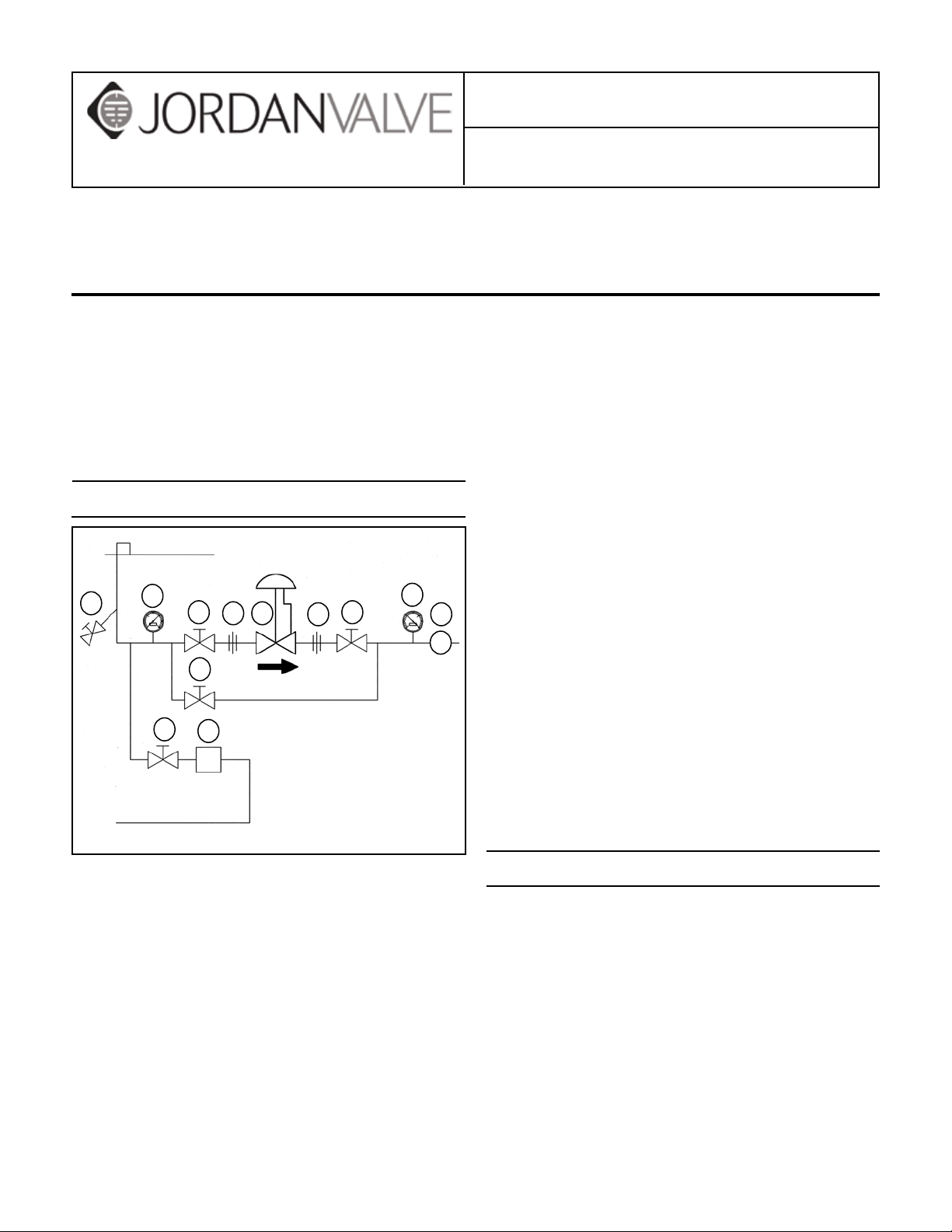
Ideal Installation
vent water hammer, and to obtain faster response.
7. If possible, install a relief valve downstream from
Main Steam Line
the valve. Set at 15 psi above the control point of
the valve.
8. In hot vapor lines, upstream and downstream pip-
3
4
1
1
52
By-Pass Line
1
2
4
6
R
ing near the valve should be insulated to minimize
condensation.
9. In gas service, if the control pressure (downstream)
is 25% of the inlet pressure or less, expand the
outlet piping at least one pipe size. A standard
tapered expander connected to the outlet of the
valve is recommended.
1
7
Condensate Return Line
1. Shut off Valve
2. Pipe Union
3. Strainer and Drain Valve
4. Pressure Gauge
5. Jordan Regulator
6. Relief Valve
7. Steam Trap
10. Where surges are severe, a piping accumulator is
recommended.
11. On steam control applications, install a steam trap
with sufficient capacity to drain the coil or condenser. Be sure to have a good fall to the trap, and no
backpressure. Best control is maintained if the coil
or condenser is kept dry.
1. To protect the valve from grit, scale, thread chips
and other foreign matter, ALL pipelines and piping
components should be blown out and thoroughly
cleaned before the installation process begins.
2. Shutoff valves, pressure gauges and by-pass piping
should be installed as indicated in the Ideal Installation Schematic to provide easier adjustment, operation, and testing.
3. A line strainer should be installed on the inlet side
of the valve to protect it from grit, scale and other
foreign matter. A 0.033 perforated screen is usually
suitable for this purpose. Line strainers are available from Jordan Valve.
4. For best control, 3’ 0” straight sections of pipe
should be installed on either side of the valve.
Start-Up
1. Fully open the outlet shut-off valve.
2. Slowly open the inlet shut-off valve.
3. Slowly open and close the outlet shut-off valve
several times. This fully strokes the valve to insure
satisfactory operation.
4. With the outlet shut-off valve open, slowly screw
down the adjusting screw until the desired pressure is shown on the outlet pressure gauge.
5. To change the controlled pressure, turn the adjusting screw clockwise to increase pressure, counterclockwise to decrease pressure.
6. Body and cap bolts should be retightened per
torque procedures after valve reaches operating
temperature.
Page 2
Maintenance
Caution: Ensure that the valve is de-pressurized before loosening any fittings or joints. The following
steps are recommended before performing any maintenance on the valve:
1. Close the inlet shut-off valve.
2. Allow pressure to bleed off through the downstream piping. Do not attempt to reverse the flow
through the valve by bleeding pressure from the
upstream side of the valve.
3. When the pressure gauges indicate that all pressure has been removed from the system, close the
outlet shut-off valve. The valve may be removed
from the line and serviced.
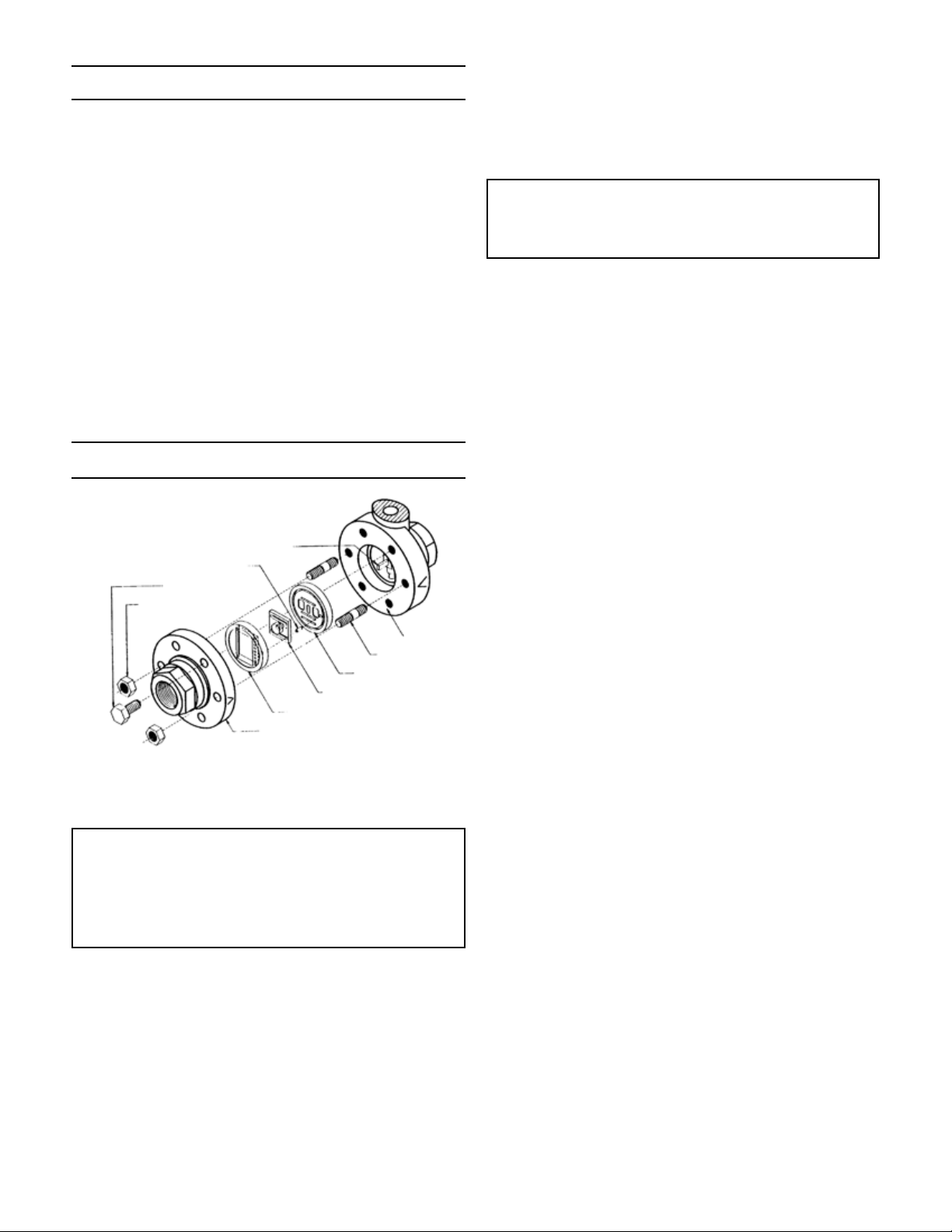
Note: Refer to the drawing at the end of this document for description and proper orientation of parts.
Valve Seats
Disc Pin (14)
Index Pin (21)
Cap Screws (20)
Hex Nuts (2)
on the valve body. (NOTE: discs that can be rotated
180° without affecting the stroke may not have arrows.) Lift straight up on the disc (17). Place the
disc on the bench lapped surface facing up. Remove the index pin (21).
It is imperative that the disc pin (14) assembly is not
rotated when disassembling, cleaning or reassembling, since this affects the stroke adjustment of the
valve.
4. Invert the body and lightly tap on the exterior to remove the plate (16). Let the plate drop out into your
hand, and place it on the bench with the lapped
surface facing up. If the plate sticks lightly tap on
the back of the plate with a soft blunt object; push
the plate (16) out evenly.
5. Clean all the parts, body and cap with solvent. Inspect body and cap bores for damage. If the parts
are scarred, do not attempt to re-lap them, but return them to the factory for repair or replacement.
6. The vertical sections of the disc guide (18) serve
as guides for the disc (17) while stroking. A 0.005
feeler gauge should be used to check for clearance
between this surface and the side of the disc. If the
clearance is less, clean the guide surfaces in the
disc guide with a fine file.
B. REASSEMBLY
Body (12)
Studs (2)
Valve Plate (16)
Valve Disc (17)
Disc Guide (18)
Cap (19)
A. DISASSEMBLY
Jordan Valve Sliding Gate Seats are lapped to
light band flatness. Maintaining such tolerances
is of paramount importance for your assurance of
excellent control and tight shutoff. DO NOT use
metallic objects in removing the seats. Care in
handling is important.
1. Following the Maintenance procedures to remove
the valve from line.
2. Note scribes “<” on the side of the body (12) and
cap (19). Secure the body flats in a vise. Remove
the cap bolts (20) and two nuts from the studs. Lift
the cap straight up.
3. Remove the disc guide (18) by lifting straight up –
protect the lapped surfaces on both sides of the
disc guide. Before removing, check the disc (17)
for a stamped arrow. This arrow points to the “<”
1. Lightly coat the outer ring on the unlapped side or
the plate (16) with anti-seize compound.
2. Place the plate (16) in the body, lapped surface facing the cap. The index-pin hole should be on the
same side of the body as the “<” on the body. Align
the disc pin (14) so that it is centered in the body
bore and that it protrudes through the center slot in
the plate (16). Place the disc (17) on the plate (16),
engaging the disc pin (14). The arrow on the disc
(17) should point to the index-pin hole. Insert the
index-pin (21) in the hole.
3. Coat the outer ring on the side of the disc guide
without the index pin hotel, with a light coating of
anti-seize compound.
4. Place the disc guide onto the plate (16), engaging the index pin (19). Rotate the assembly slightly
until the slot openings in the disc are parallel to
the openings in the plate, and perpendicular to the
stem. Stroking the valve will aide in this alignment.
5. Align the “>” on the cap (19) with the “<” on the
body (12), and place the cap over the two studs in
the body.
6. Install the nuts and cap bolts (20). Tighten uniformly. See page four for torque requirements and
tightening procedures.
-2-
Page 3

Diaphragm Replacement
A. DISASSEMBLY
1. Remove all of the compression from the spring (7)
by rotating the adjusting screw (1) counterclockwise until it moves freely. (Failure to remove the
compression from the spring could result in personal injury or damage to the valve.)
2. Remove the spring housing bolts (5) and spring
housing (4). Remove the spring (7) and spring seat
(6).
3. Remove the diaphragm assembly by rotating counterclockwise. The diaphragm assembly consists of
the upper diaphragm plate (8), diaphragm (9) and
lower diaphragm plate (10).
4. If the diaphragm must be replaced, secure the
upper diaphragm plate (8) in a vise. A 3/16” face
spanner wrench should be used to remove the
lower diaphragm plate (10) from the assembly.
5. Remove the diaphragm (9) and reassemble in reverse order.
B. REASSEMBLY AND STROKE ADJUSTMENT
Stroke Adjustment
1
Orifice
Disc
Cap
Disc Guide
Plate
Disc Pin
Vase
1. The stroke adjustment is made with the spring housing and adjusting
spring removed from the valve.
2. The valve orifices should be open and in perfect alignment when the
diaphragm assembly is pressed against the valve body as illustrated.
3. The valve stroke adjustment is determined by how far the stem is
screwed into the diaphragm plate. Rotate the diaphragm assembly to
raise or lower the valve disc. Unthread the diaphragm assembly partially
to lower the disc or thread the stem deeper into the assembly to raise the
disc.
Stem
3
Lower
Diaph. Plate
Upper
Diaph. Plate
Diaphragm
1. Note that the valve stroke adjustment is determined by how far the diaphragm assembly is
screwed onto the stem. Screw the diaphragm assembly onto the stem until the disc pin is centered
in the valve body.
2. Push the diaphragm assembly down against the
valve body and check the orifice alignment of the
disc (17) and the plate (16). The orifices should be
fully open and in perfect alignment.
3. If the orifices are not in perfect alignment, rotate
the diaphragm assembly counterclockwise to lower
the disc, and clockwise to raise the disc.
4. The total stroke of the Mark 60 is equal to the orifice width plus 1/32” overlap. Consequently, perfect adjustment is required for proper operation.
5. When seats are in perfect alignment, proceed with
the assembly of the spring housing.
6. Place the spring (7) on the upper diaphragm plate
(8) and the spring seat (6) on the spring.
7. If the diaphragm is metal, be sure that the diaphragm is aligned in the body recess. This recess
also aligns the spring housing (4). Be sure that the
bleed hole is facing downstream.
8. If the diaphragm is elastomer, make sure that after the seats are in perfect alignment that the bolt
holes are in alignment. If an adjustment needs to
be made to align the bolt hole, make the adjustment by turning the diaphragm assembly clockwise.
9. Install and tighten the spring housing bolts (5) per
the torque instructions on the back page.
If Stroke is Too Short:
To correct, turn the diaphragm assembly
toward you (unthreading it from the stem)
bringing the disc orifices into alignment with
the plate orifices.
If Stroke is Too Long:
To correct, turn the diaphragm assembly
away from you (threading it farther onto the
stem) bringing the disc orifices into alignment with the plate orifices.
-3-
Page 4

Disc Pin
1. Remove the disc and the plate, following the procedure outlined under VALVE SEATS.
2. Remove the diaphragm as outlined under DIAPHRAGM REPLACEMENT.
3. Holding the disc pin assembly with an open-end
wrench, loosen the locknut (13). The stem (11) can
now be unscrewed from the disc pin (14) and the
locknut removed from the stem..
4. Remove the stem (11) upward through the diaphragm area and the disc pin (14) through the body
orifice.
5. Check the condition and clean all parts. Clean the
lower guide hole in the valve body and replace defective parts.
6. Reassemble in reverse order and follow the procedures outlined under DIAPHRAGM REPLACEMENT
and VALVE SEATS for proper adjustment. When reassembling, thread the stem (11) fully into the disc
pin (14) and then tighten the locknut (13).
Troubleshooting
If You Experience Erratic Control:
Oversizing causes cycling and hunting, and reduc-
es the rangeability of the valve. Make certain that
your sizing is correct.
Steam traps downstream may require maintenance.
Safety valve may be defective and need repair.
There may be excessive foreign matter on the
seats, and seats should be removed and cleaned.
Valve stroke may need readjustment.
Valve disc may not be moving freely. Check disc
guide clearance and correct if needed.
NOTE: Any parts ordered without a valve serial number
that are found to be incorrect are subject to up to a minimum 25% restock charge when returned.
Torque Values
Bolt Pattern / Torquing Sequence
5
3
2
(or multiples)
Torque for Bolts Connecting Cap to Body (in. - lbs.)
Valve Size
1/2” through 2” 140 200
1/2” through 2” 200
1
4
6
6 bolts
Valve Body Material
Bronze
Torque for Spring Housing Screws
Valve Size Torque (in. - lbs.)
Ductile Iron, Carbon Steel,
3
7
5
2
(or multiples)
or Stainless Steel
1
6
8
4
8 bolts
If Valve Will Not Operate:
Diaphragm may be ruptured and require replace-
ment.
Adjusting spring may be broken and require re-
placement.
Spring may be set improperly and require resetting.
Ordering Spare Parts
Use only genuine Jordan Valve parts to keep your valve
in good working order. So that we can supply the parts,
which were designed for your valve, we must know exactly which product you are using. The only guarantee to
getting the correct replacement parts is to provide your
Jordan Representative with the valve serial number. This
number is located on the valve identification tag. If the
serial number is not available, the parts needed for your
valve might be determined using the following information: Model Number, Valve Body Size, Seat Material and
Cv Rating, Spring Range and Set Point, Trim Material, Part
Name - Number and Quantity.
Page 5

Illustration and Parts List
1
2
6
8
5
9
24
22
7
4
10
11
23
13
17
19
14
20
18
16
Bolts shown rotated
12
30° out of position
Item Description Item Description
1 Adjusting Screw *13 Stem Locknut
2 Locknut (Adjusting Screw) *14 Disc Pin
4 Spring Housing *16 Plate
5 Bolt (Spring Housing) *17 Disc
6 Spring Seat *18 Disc Guide
7 Spring 19 Cap
8 Upper Diaphragm Plate 20 Bolt (Body)
*9 Diaphragm 21 Index Pin (not shown)
10 Lower Diaphragm Plate 22 Name Plate
* 11 Stem 23 Stud (Body)
12 Body 24 Nut (Body Stud)
* Recommended Spare Parts
Bulletin IM-MK60-0111
3170 Wasson Road • Cincinnati, OH 45209 USA
Phone 513-533-5600 • Fax 513-871-0105
info@richardsind.com • www.jordanvalve.com
 Loading...