

Page 1
I & M Mark 5108 Series
3170 Wasson Road • Cincinnati, OH 45209
Phone 513.533.5600 • Fax 513.871.0105 (f)
info@richardsind.com • www.jordanvalve.com
Warning: Jordan Valve Control Valves must only be used, installed and repaired in accordance with these Installation & Maintenance Instructions. Observe all applicable public and company codes and regulations. In the event
of leakage or other malfunction, call a qualified service person; continued operation may cause system failure or
a general hazard. Before servicing any valve, disconnect, shut off, or bypass all pressurized fluid. Before disassembling a valve, be sure to release all spring tension.
IntroductIon
The Mark 5108 may be generically described as
a back pressure control valve, i.e., it controls the
pressure at its inlet. With this type of control, the
Mark 5108 may be employed in two different ways:
1. As a Pressure Relief Valve. Here the 5108
is installed on a bypass from a main line. It
opens to relieve any pressure above its set
point.
2. As a Pressure Sustaining Valve. Here the
Mark 5108 is installed in the main line itself. It
functions to control the incoming pressure at
the set point, or more commonly, to prevent
the pressure from falling below a
predetermined minimum. For example, it may
be installed on the discharge of a pump to
ensure that the pump remains "on its curve."
Installation & Maintenance Instructions for the
Mark 5108 Back Pressure Regulating Valve
4. Flow Control Valve, a needle-type valve
which provides adjustable, restricted flow in
one direction, and free flow in the opposite
direction. On the Mark 5108, the flow control
valve is connected as a closing speed
control.
5. The Y-Strainer (standard on water
service valves) or Mark 5123 Inline Strainer
(standard on fuel service valves). The strainer
protects the pilot system from solid
contami nants in the line fluid.
6. Two Ball Valves (standard on water service
valves, optional on fuel service valves), useful
for isolating the pilot system for maintenance
or trouble shooting.
At user option, the 5108 may also be equipped with
the following:
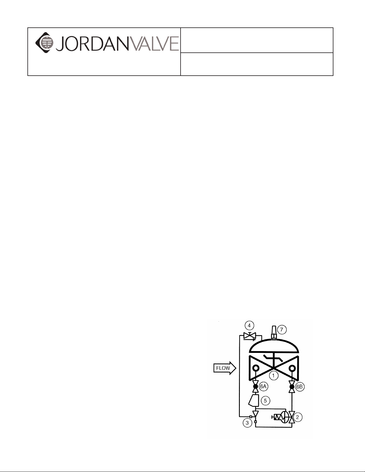
The Mark 5108 consists of the following components,
arranged as shown on the schematic diagram:
1. Basic Control Valve, a hydraulically
operated, diaphragm-actuated, globe or
angle valve which closes with an elastomer-on-
metal seal.
2. Pressure Relief Pilot, a two-way, normally
closed pilot valve which senses up-stream
presure under its diaphragm and balances it
against an adjustable spring load. An increase
in upstream pressure tends to make the pilot
open.
3. Ejector, a simple "tee" fitting with a fixed orifice
in its inlet port. It provides the proper pressure to
the diaphragm chamber of the main valve
depending on the position of the pressure relief
pilot.
1. Visual Indicator.
2. Limit Switch Assembly (includes visual
indicator).
3. Opening Speed Control.
Page 2

Mark 5108 SerieS Back PreSSure regulating ValVe
theory of operatIon
To understand how the Mark 5108 operates, it is best
to start with the Ejector (3). Due to the orifice in its
upstream port, the ejector creates a pressure drop
proportional to the flow through it. The flow through the
ejector is in turn controlled by the degree of opening of
the Pressure Relief Pilot (2). The wider the pilot opens,
the greater the flow through the ejector and the lower the
pressure downstream of the orifice. Conversely, the more
the pilot closes, the lower the flow through the ejector
and the greater the pressure downstream of the orifice.
Now note that the diaphragm chamber of the Main Valve
(1) is connected to the branch port of the ejector and is
thus downstream of the orifice. Therefore, the pressure in
the diaphragm chamber of the main valve is effectively
controlled by the pressure relief pilot in the manner
described above. As the pilot opens, the diaphragm
pressure decreases and the main valve opens; as the
pilot closes, the diaphragm pressure increases and the
main valve closes.
If the Mark 5108 is installed as a pressure relief valve,
the pressure upstream of the main valve is normally
below the set point of the relief pilot. Therefore, the pilot
is fully closed, and so is the main valve. However, if, for
any reason, the pressure rises above the set point, the
pilot will open, and the main valve will follow in turn. The
net effect is that the main valve will open and control
the pressure at the set point, not allowing it to rise any
further. Once pressure returns to normal, the pilot and
main valve will return to the closed position.
If the Mark 5108 is installed as a pressure sustaining
valve, the pressure upstream of the main valve is
normally above the set point of the relief pilot. Therefore,
the pilot is wide open as is the main valve. However, if
system demand increases to the point that the upstream
pressure tries to fall below the set point, the pilot will
start to close and the main valve will follow, throttling as
required to keep the pressure from falling any further.
InstallatIon
Figure 1 shows a typical installation of an angle pattern
Mark 5108 in pressure service. Here it will relieve the
startup surges of the centrifugal pump, but this time in
pressure sustaining service. Here it will keep a
minimum back pressure on the pump to keep it from
running off the right of its curve in periods of high system
demand. These illustrations are intended only as rough
guides for valve installation, as indeed there are many
other places in a system where the Mark 5108 can be
effectively employed. However, note the use of isolation
valves. While these do not affect the operation of the
5108, they can be extremely useful if the valve needs to
be isolated from the line for maintenance or repair.
For full installation details, the user is referred to the Main
Valve section of this manual.
start- up and adjustments
The following procedures should be followed in the order
presented in order to affect an initial startup of the Mark
5108. Note that the procedure differs somewhat between
a pressure relief valve and a pressure sustaining valve.
Procedure A. Pressure Relief Valve
1. Install a pressure gauge of the proper range
upstream of the Mark 5108. The unused inlet
side port in the main valve body may be
used for this purpose if there is no
convenient location in the upstream piping.
2. Remove the plastic cap from the pressure relief
pilot (2) and loosen the adjusting screw jam nut.
Turn the adjusting screw clockwise to a full stop.
3. Loosen the adjusting screw jam nut on the flow
control valve (4) (closing speed control). Turn
the adjusting screw clockwise to a full stop, then
counterclockwise three full turns.
4. Make sure both pilot system isolation ball valves
(6A and 6B) are open.
5. Start the pump or otherwise start the system
flowing. The main valve at this time should
be fully closed.
6. Carefully loosen a pipe plug in the main valve
bonnet until fluid begins to discharge around
the threads. When only clear fluid (no air)
is discharging, retighten the plug.
-2-
Page 3

Mark 5108 SerieS Back PreSSure regulating ValVe
7. While observing the inlet pressure gauge ,retard
flow in the system by closing valves or otherwise
reducing demand until the pressure increases to
approximately 5 psi above the desired set point.
8. Slowly turn the adjusting screw of the pressure
relief pilot (2) counterclockwise until the valve
opens and the pressure falls to the set
point. Tighten the adjusting screw jam nut and
replace the plastic cap.
9. Increase flow in the system or otherwise in-
crease demand until pressure returns to normal.
Observe the closing speed of the valve. Ideally,
the valve should close just slow enough
to avoid inducing any secondary surges
in the system. Turn the adjusting screw of the
flow control valve (4) clockwise to
decrease closing speed; counterclockwise to
increase closing speed. CAUTION: Do
NOT adjust the/low control valve fully closed. To
do so can keep the valve from closing at all.
10. Shut down the pump.
Procedure B. Pressure Sustaining Valve
1. Install a pressure gauge of the proper range
upstream of the Mark 5108. The unused inlet
side port in the main valve body may be used
for this purpose if there is no convenient location
in the upstream piping.
2. Remove the plastic cap from the pressure relief
pilot (2) and loosen the adjusting screw jam nut.
Turn the adjusting screw clockwise to a full stop.
3. Loosen the adjusting screw jam nut on the flow
control valve (4) (closing speed control). Turn
the adjusting screw clockwise to a full stop, then
counterclockwise three full turns.
4. Make sure both pilot system isolation ball valves
(6A and 6B) are open.
5. Start the pump or otherwise start the system
flowing. The main valve at this time should be
fully closed.
6. Carefully loosen a pipe plug in the main valve
bonnet until fluid begins to discharge around the
threads. When only clear fluid (no air) is
discharging, retighten the plug.
7. Turn the adjusting screw of the pressure relief
pilot (2) counterclockwise until it is loose enough
to be turned with the fingers. The main
valve should open fully.
8. Observing the inlet pressure gauge, open valves
or otherwise increase flow until the pressure falls
to a point approximately 5 psi below the desired
set point.
9. Slowly turn the adjusting screw of the pressure
relief pilot (2) clockwise until the pressure rises
to the set point. Tighten the adjusting screw jam
nut and replace the plastic cap.
10. Shut down the pump.
maIntenance
Because of the simplicity of design of the Mark 5108,
required maintenance is minimal. However, the following
checks, periodically performed, can do much to keep
the valve operating properly and efficiently.
1. Check for chipped or peeling paint. Touch up as
required.
2. Check for leaks at fittings and around flanges
and connections. Tighten as required.
3. If the valve is equipped with a Y-strainer, check
the screen for buildup of solid material. Clean as
required. This point is most important, as 1
a clogged strainer can keep the valve
from closing. On new installations, it is
recommended that the strainer be checked
every day or two until experience dictates a
greater or lesser interval. Strainer maintenance
is covered in detail on a special page
later in this manual.
troubleshootIng
In the event of malfunction of the Mark 5108, the
following guide should enable the technician to
isolate the specific cause of the problem and take the
appropriate corrective action.
A. Main Valve fails to Open:
1. Valve closed upstream or downstream of the
Mark 5108. Open as required.
2. Downstream pilot system ball valve (6B) closed.
Open as required.
3. Pressure relief pilot (2) adjusted too far clock-
wise. See Adjustment instructions.
4. Diaphragm of pressure relief pilot (2) ruptured.
This will be evidenced by a discharge of
fluid from the vent hole in the pilot bonnet.
Replace diaphragm.
5. Stem of pressure relief pilot (2) binding. Disas-
semble pilot and determine cause.
6. Stem of main valve binding. Disassemble valve
and determine cause.
-3-
Page 4

Mark 5108 SerieS Back PreSSure regulating ValVe
B. Main Valve fails to Close:
1. Upstream pilot system ball valve (A) closed.
Open as required.
2. Strainer (5) clogged. Clean as required.
3. Closing speed control adjusted fully closed.
Open as required. See Adjustment instructions.
4. Pressure relief pilot (2) adjusted too far counter-
clockwise. See Adjustment instructions.
5. Close the downstream pilot system ball valve
(6B).
(a) If valve closes, proceed to Step 6.
(b) If valve remains open, proceed to Step
7.
6. Pressure relief pilot (2) stem binding or seat
badly deteriorated. Disassemble pilot
and determine cause.
7. Close both pilot system ball valves (6A and 6B)
and loosen a pipe plug in the main valve
bonnet. A continuous discharge of fluid
from the loosened plug indicates that the main
valve diaphragm is ruptured. Replace
diaphragm.
NOTE: Certain valves, predominantly those in fuel
service, are assembled "fail closed." In this case, a
ruptured diaphragm would keep the valve from opening,
rather than keep it from closing. To determine which type
you have, examine the "bridgemark" cast into the side
of the main valve body and compare it with the diagram
below.
(a) If the leak stops, the problem is in the
pressure relief pilot (2), likely a
damaged seat. Disassemble
pilot and determine cause.
(b) If the leak continues, the problem is
in the main valve, likely a damaged seat.
Disassemble valve and determine
cause.
8. Main valve stem binding or object caught in
valve. Disassemble valve and determine
cause.
C. Main Valve Opens and Closes, but Leaks
When Closed
1. Pressure relief pilot (2) adjusted slightly too low.
See Adjustment instructions.
2. Close downstream pilot system ball valve (6B).
Jordan Valve, a division of Richards Industries
3170 Wasson Road • Cincinnati, OH 45209
513.533.5600 • 800.543.7311 • 513.871.0105 (f)
info@richardsind.com • www.jordanvalve.com
 Loading...