

Page 1
I & M 508/608 3/4"-1-1/4"
3170 Wasson Road • Cincinnati, OH 45209 USA
Phone 513-533-5600 • Fax 513-871-0105
E-Mail: info@richardsind.com • www.jordanvalve.com
Installation & Maintenance Instructions for
Mark 508/608 Gas Pressure Regulators
Warning: Jordan Valve Pressure Regulators must only be used, installed, and repaired in accordance with these Installation & Maintenance Instructions. Observe all applicable public and company codes and regulations. In the event of leakage or other malfunction, call a qualified service person; continued operation may cause system failure or a general
hazard. Before servicing any valve, disconnect, shut off, or bypass all pressurized fluid. Before disassembling a valve, be
sure to release all spring tension.
Please read these instructions carefully!
Your Jordan Valve product will provide you with long, troublefree service if it is correctly installed and maintained. Spending
a few minutes now reading these instructions can save hours of
trouble and downtime later. When making repairs, use only genuine Jordan Valve parts, available for immediate shipment from
the factory.
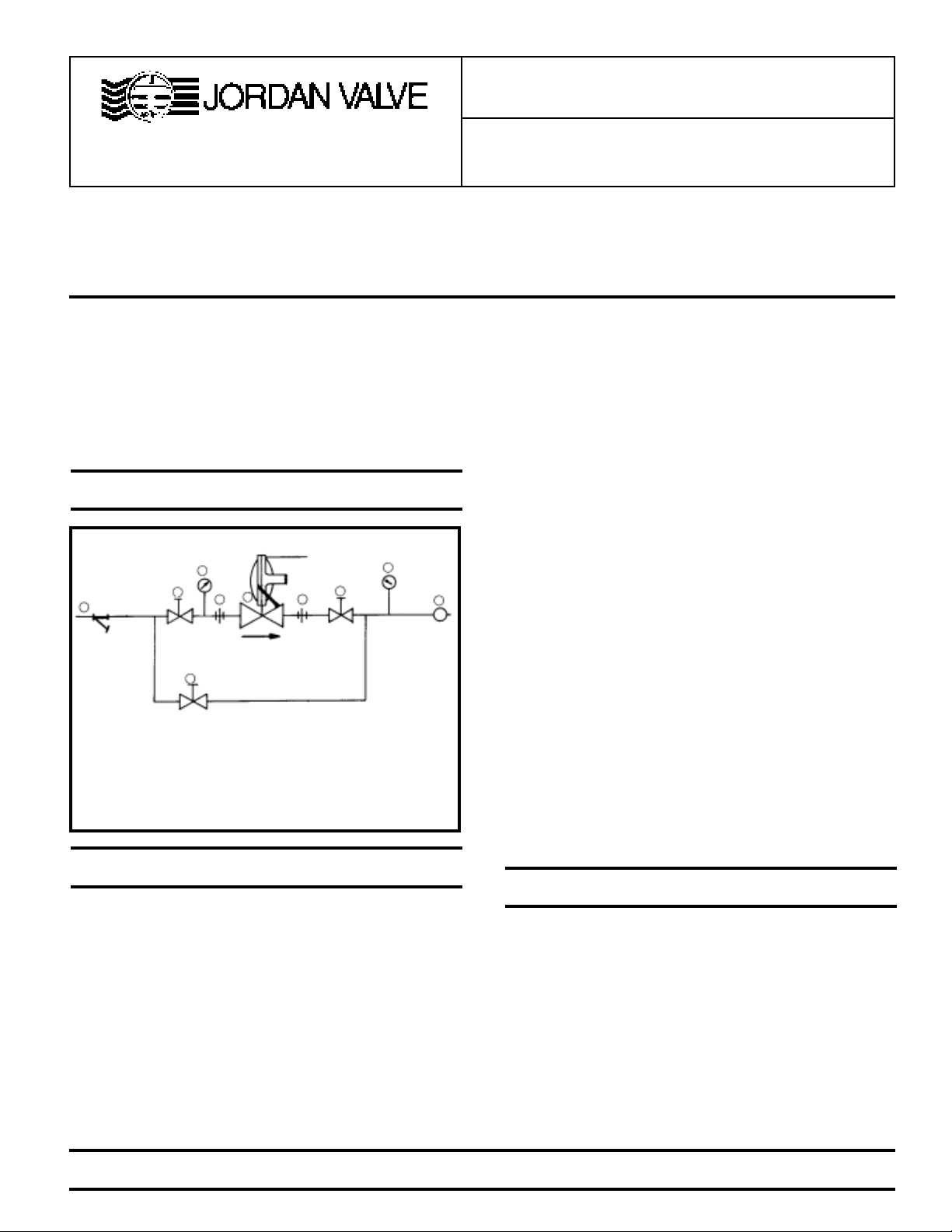
Ideal Installation Schematic
3
Figure 1
Vent Line
4
1
1
5
By-Pass Line
(if used)
1
22
1 Shut-off Valves
2 Pipe Union
3 Strainer
4 Pressure Gauges
5 Jordan Regulator
6 Relief Valve
4
6
R
4. A line strainer should be installed on the inlet side of the
regulator to protect pipe from grit, scale and other foreign
matter. A .033 perforated screen is usually suitable for this
purpose. Line strainers are available from Jordan Valve.
5. The flow arrow on the regulator body must be pointed in the
direction of flow. The regulator may be installed in any position. The actuator may be rotated to any position relative to
the body. (See sizing.) Loosen the union nut and position the
actuator. Pull the union nut up hand-tight, then tighten
1/4 turn. (The union nut is 8-sided and may be used as a
guide.)
6. Provisions are provided to vent the case from the top or bottom by a 1/4” pipe tap opening. One opening is plugged, the
other has a screened (bug) vent. Reverse these if it is desired open vents should point downward; a street elbow can
be used if needed. Some installations will require that this
vent be piped to some location external to the regulator. When
remote piping is used, 1/4” size is adequate. NEVER BLOCK
OFF THE VENT LINE. Follow local regulations.
7. Install a relief valve downstream from the regulator to protect
downstream components from over-pressurization. Generally, the setting of the relief valve should be at least 20%
greater than the regulator set point. It must have adequate
flow capacity to protect the downstream components should
the regulator fail to shut off.
8. Operate the regulator within its rated pressure and temperature. The standard MK 508/608 is rated at 150 psig max
(inlet or outlet section) at -20 to +200°F. Regulator ratings
and materials of construction are listed on the valve name
plate.
Preferred Installation
1. To protect the regulator from grit, scale, thread chips and
other foreign matter, ALL pipelines and piping components
should be blown out and thoroughly cleaned before the installation process begins.
2. Shutoff valves, pressure gauges and by-pass piping should
be installed as indicated in the Ideal Installation Schematic
to provide easier adjustment, operation, and testing.
3. In preparing threaded pipe connections, care should be exercised to prevent pipe sealing compound from getting into
the pipe lines. Pipe sealing compound should be used sparingly, leaving the two end threads clean. Jordan recommends
Teflon tape.
PROTECT VALVES WITH LINE STRAINERS
Start-Up
1. Fully open the outlet shut-off valve.
2. Slowly open the inlet shut-off valve.
3. Slowly open and close the outlet shut-off valve several times.
This fully strokes the valve to insure satisfactory operation.
4. With the outlet shut-off valve open and preferably at a low
flow, slowly turn the adjusting screw until the desired pressure is shown on the pressure gauge.
5. To change the controlled pressure, turn the adjusting screw
clockwise to increase pressure, and counterclockwise to decrease pressure.
Page 2

Trouble Shooting
Trouble
Erratic
Control
Cannot Set
Outlet
Pressure
Will Not Operate
Possible Cause and Cure
• Oversizing causes cycling and hunting
and reduces the rangeability of the valve.
Make certain that your sizing is correct.
• Attempting to exceed flow capacity.
Make certain that your sizing is correct.
• Blocked vent line or vent passage in
spring housing. Clean.
• Inlet pressure varying greatly. Stabilize or
use second regulator to control inlet
pressure closer.
• Aspirator blocked. Clean.
• Orifice too large for inlet pressure.
• Improper spring.
• Diaphragm ruptured. Replace.
• Adjusting spring broken. Replace.
• Improper spring setting. Reset.
Maintenance
WARNING:
Be sure that there is no pressure in the valve before loosening any fittings or joints. The following steps are recommended:
1. Close the inlet shut-off valve, and by-pass valve.
2. Back off adjusting screw to allow inlet pressure to open
seats.
3. Allow pressure to bleed off through downstream piping.
4. When the inlet pressure gauge indicates no pressure
in the line, close the outlet shut-off valve.
Refer to the drawings for the proper orientation of the parts
and for proper nomenclature.
A. DIAPHRAGM OR GASKET REPLACEMENT
1. Remove all pressure from the line as outlined under WARNING.
2. Remove the compression of the adjusting spring (22) by rotating the adjusting screw (19) counterclockwise.
3. Loosen the spring housing bolts (16) and remove spring
housing.
IF DIAPHRAGM IS NOT BEING REPLACED, SKIP STEPS 4
THRU 8
4. Remove diaphragm subassembly by sliding it away from the
valve body to disengage the lever arm (7).
5. Hold the lower diaphragm plate (5) and remove the screw
(6), separating the parts.
6. Clean the surfaces on the upper and lower diaphragm plates
that the diaphragm (3) seats against. Clean and degrease
the threads on the lower diaphragm plate and the screw.
(Degrease with Loctite primer T.)
7. Assemble the upper and lower diaphragm plates to the new
diaphragm with the screw. (Apply a few drops of Loctite #290
to the screw threads to lock the parts together.) The hole
through the lower diaphragm plate must align with any pair
of opposite holes in the diaphragm so that it will properly
engage the lever when reassembled into the valve.
8. Clean the flange surface on the diaphragm housing and reinstall the diaphragm subassembly onto the lever arm.
9. Clean the flange surface on the spring housing and install a
new gasket. The gasket may be temporarily held in place
using a few dabs of grease.
10. Set the spring housing on top of the diaphragm housing.
Using a 6” long screwdriver, or similar tool, reach through
the spring housing and push the diaphragm down to align
the diaphragm holes with the housings’ holes.
11. Drop the bolts into place and attach the lockwashers and
nuts, finger-right.
12. Continue to push the diaphragm down and snug-up the
bolts.
13. Evenly torque the bolts as described in the drawing, Figure
3.
14. Install the spring and adjusting screw. (Adjusting spring per
start-up instructions and replace cap.)
B. SEAT INSERT, PLUG, OR ASPIRATOR REPLACEMENT
CAUTION: WHEN REPLACING A PLUG OR SEAT INSERT,
THE LEVER MUST ALSO BE REPLACED TO INSURE SHUTOFF.
1. Remove all pressure from the line as outlined under WARNING.
2. Loosen the union nut (24) and separate the actuator from the
body.
MK608 only:
3a. Inspect the plug (11) and seat insert (26) to determine if
replacement is required. Replace if there are signs of wear
or uneven seating on either part.
4a. To replace the seat, simply unscrew it from the body using a
7/8" thinwall socket wrench. Install the new seat. An antiseize
compound applied to the threads will aid in future removal.
5a. To replace the plug or aspirator (12), disassemble the ac-
tuator as described in steps A2, A3, A4.
MK508 only:
3b. Remove the bottom cap (32) and gasket (33). Remove
retainer screw (34) and seat retainer (35) to determine if
replacement of the seat (26) or soft seat insert (36) is required. Replace if there are signs of wear or uneven seat
on either part.
4b. To replace the sat (26), simply unscrew it from the body
along with the o-ring (31) using a 7/8" thinwall socket wrench.
Install the new o-ring and seat. Apply antiseize compound
to the threads to aid in future removal. To replace the soft
seat insert, carefully remove it from the seat retainer with a
pocket knife and insert the new one in its place. Use of a
suitable rubber to metal adhesive is required.
5b. To replace the stem (11), or aspirator (12), disassemble the
actuator as described in steps A2, A3, and A4.
MK508/608:
6. Remove the two screws (9) fastening the lever arm bracket
(8) to the diaphragm housing and lift out the lever arm bracket
with the lever.
7. Inspect aspirating hole in aspirator to be sure it is clean.
Remove and replace aspirator if stem guide bores are worn.
Remove and replace plug.
8. Remove the screws from the lever arm bracket and clean the
threads. Degrease with Loctite Primer T. Also clean and
degrease the tapped holes in the diaphragm housing.
Page 3

9. Remove the pin (10), replace the lever and reassemble with
the screws.
10. Apply a drop of Loctite #290 to each screw and reinstall the
lever arm bracket. Align the slot in the plug's stem with the
new lever arm and tighten the pivot bracket's mounting
screws. Check for free movement. Be certain that there is a
gasket (29) between the aspirator flange and the diaphragm
housing, and a gasket (30) in the body cavity where the
aspirator fits.
11. Re-attach body and actuator with the union nut (being care-
ful to align the aspirator tube to the slot in the body). Pull up
hand-tight, then tighten further 1/4 turn. (The union nut is 8sided and may be used as a guide).
12. If lever arm was replaced, apply 25-150 psi pressure through
outlet. This will set linkage and prevent overpressure (in
operation) from bending the linkage and causing set point
changes. Seat leakage may be checked by observing any
leakage from inlet.
MK508 only
13. Reverse steps 3b and 4b to complete valve-reassembly.
Seat leakage may be checked by observing any leakage from
inlet.
bly of a new diaphragm subassembly is covered in A1 thru
A7.)
10. If a new spring housing is being used, take the new spring
housing and carefully drive a new stop pin (23) into the
hole in the housing neck with a hammer. (This serves as a
spring adjusting screw stop and must be installed.)
11. Clean the flange surface on the spring housing and reinstall
a new gasket (13). The gasket may be temporarily held in
place using a few dabs of grease.
12. Set the spring housing on top of the diaphragm housing.
Using a 6” screwdriver, or similar tool, reach through the
spring housing and push the diaphragm down to align the
diaphragm holes with the housings’ holes.
13. Drop the bolts into place and attach the lockwashers and
nuts, finger-tight.
14. Continue to push the diaphragm down and snug-up the
bolts.
15. Evenly torque the bolts as described in Figure 3.
16. Apply 25-150 psi pressure through valve outlet. This will set
linkage and prevent overpressure in operation from bending the linkage and causing setpoint changes. Seat leakage may be checked by observing any leakage from inlet.
C. SPRING REPLACEMENT.
1. To replace a spring, remove the cap (21) and the adjusting
screw (19). Then remove the spring.
CAUTION: IF A DIFFERENT RANGE SPRING IS BEING INSTALLED, BE SURE THE PROPER ADJUSTING SCREW IS
USED. (THE 3.5 psi RANGE USES DIFFERENT ADJUSTING
SCREW.) FAILURE TO OBSERVE THIS CAUTION COULD RESULT IN VALVE DAMAGE OR FAILURE TO SHUT OFF. IT IS
RECOMMENDED THAT A NEW TAG BE ISSUED FOR THIS
VALVE WITH CORRECT SPRING RANGE.
2. Reinstall spring and adjusting screw. Adjust spring per startup instructions. Replace cap.
D. DIAPHRAGM OR SPRING HOUSING REPLACEMENT.
CAUTION: IF THE SPRING HOUSING IS TO BE REPLACED,
THE LEVER MUST BE REPLACED TO INSURE SHUT-OFF.
1. Remove all pressure from the line as outlined under WARNING.
2. Remove the compression of the spring (22) by rotating the
adjusting screw (19) counterclockwise.
3. Loosen the spring housing bolts (16) and remove spring
housing.
4. Remove diaphragm subassembly by sliding it away from the
valve body to disengage the lever arm (7).
5. Remove the two screws (9) fastening the lever arm bracket to
the diaphragm housing and lift out the lever arm bracket with
the lever arm.
6. Remove the screws from the lever arm bracket and clean the
threads. Degrease with Loctite Primer T. Also clean and
degrease the tapped holes in the diaphragm housing.
7. Remove the pin (10), replace the lever arm and reassemble
with the screws.
8. Apply a drop of Loctite #290 to each screw and reinstall the
lever arm bracket. Align the slot in the plug’s stem with the
new lever arm and tighten the pivot bracket’s mounting
screws. Check for free movement.
9. Clean the flange surface on the diaphragm housing and reinstall the diaphragm subassembly onto the lever. (Assem-
Torque Procedure
1. Install all bots hand-tight.
2. Torque the bolts in order of
the bolt pattern to approx. 75
in-lbs
3. Retorque each bolt to 300
in-lbs, using the same bolt
pattern as shown.
3
7
2
6
5
1
8
4
8 Bolts (or multiples)
Figure 3
Page 4

Illustration & Parts List
MK508 (Insert) 3/4" - 1-1/4"
24
25
30
31
34 35 36
33
11
29
12
26
27
32
MK508/608 3/4" - 1-1/4"
14
8
10
.oN noitpircseD ytQ
13gniR-O1
23 paCmottoB 1
33)paCmottoB(teksaG1
43 wercSreniateR 1
53reniateRtaeS1
63 tresnItaeStfoS 1
24
25
30
26
27
15
4
1
5
29
Inlet
Body
Aspirator
Passage
3
2
19
21
22
6
7
28
9
13
11
12
23
Ordering Spare Parts
Use only genuine Jordan Valve parts to keep your valve in
good working order. So we can supply the parts, which were
designed for your valve, we must know exactly which product
you are using. The only guarantee to getting the correct
replacement parts is to provide your Jordan Representative with the valve serial number. This number is located
on the valve identification tag. If the serial number is not
available, the parts needed for your valve might be
determined using the following information:
• Model number
• Valve Body size
• Plug Material and Seat Size
• Spring Range or Set Point
• Trim Material
• Part Name - Number and Quantity (see parts list chart).
Note: Without a valve serial number, any parts ordered incorrectly are
subject to a minimum 25% restock charge when returned.
.oN noitpircseD ytQ .oN noitpircseD ytQ
1
2 gnisuoHgnirpS **&*1 71
3mgarhpaiD181)nwohston(tuN8
4
5
6 wercS 1 22 gnirpSegnaR 1
7mrAreveL132niPpotS1
8 tekcarBmrAreveL *1 42 tuNnoinU 1
9wercS252gniRgniniateR2
01 niPlewoD 1 62 tresnItaeS *1
11gulP*172ydoB1
21 ebuTrotaripsA 1 82 etalPemaN 1
31teksaGmgarhpaiD192teksaG1
41 neercStneV 1 03 teksaG 1
51gulPepiP1
mgarhpaiDrewoL
esaC
etalP
etalP
*161)nwohston(tloB8
ton(rehsawkcoL
)nwohs
mgarhpaiDreppU
*1 91 A/SwercSgnitsujdA 1
mgarhpaiDrewoL
*112paC1
8
Note:
* When replacing any item marked with an asterik, always
install a new lever arm (7) and follow instructions in step B12.
**When replacing spring housing, a new stop pin (23) must be
installed.
3170 Wasson Road • Cincinnati, OH 45209
Phone 513-533-5600 • Fax 513-871-0105
800-543-7311 (USA) • 800-354-0305 (Canada)
E-Mail: info@richardsind.com
URL: www.jordanvalve.com
 Loading...