

Page 1
I & M Mark 501 / 502
3170 Wasson Road • Cincinnati, OH 45209 USA
Phone 513-533-5600 • Fax 513-871-0105
info@richardsind.com • www.jordanvalve.com
Installation & Maintenance Instructions for
Mark 501/502 High Flow Back Pressure Regulators
Warning: Jordan Valve Back Pressure Regulators must only be used, installed and repaired in accordance with these
Installation & Maintenance Instructions. Observe all applicable public and company codes and regulations. In the event
of leakage or other malfunction, call a qualied service person; continued operation may cause system failure or a
general hazard. Before servicing any valve, disconnect, shut off, or bypass all pressurized uid. Before disassembling a
valve, be sure to release all spring tension.
Please read these instructions carefully!
Valve.
Install the regulator in the highest horizontal line of 5.
Your Jordan Valve product will provide you with long, trouble- free service if it is correctly installed and maintained.
Spending a few minutes now reading these instructions
can save hours of trouble and downtime later. When making repairs, use only genuine Jordan Valve parts, available
for immediate shipment from the factory.
piping to provide drainage for inlet and outlet pip-
ing, to prevent water hammer, and to obtain faster
regulation.
The ow arrow on the regulator body must be point-6.
ed in the direction of ow. The regulator may be in-
stalled vertically or horizontally without affecting its
operation.
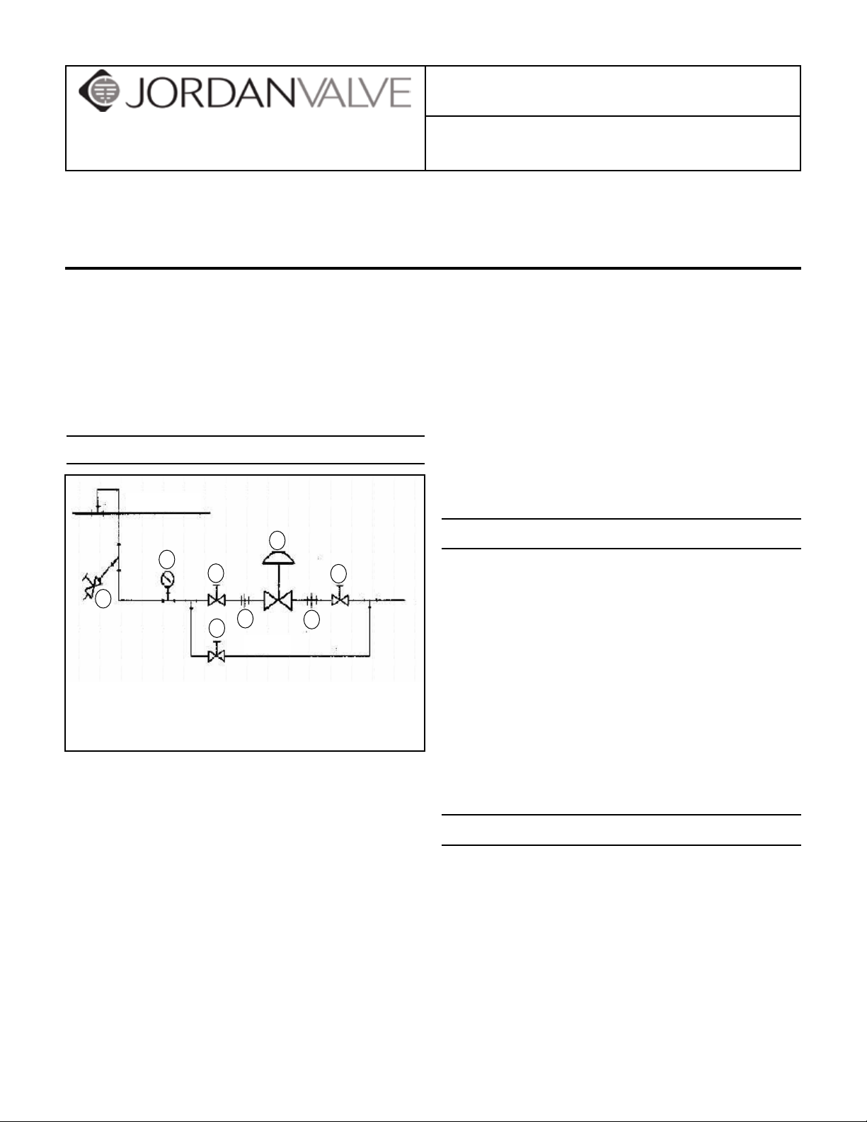
Installation
For best control, 3’ 0” straight sections of pipe should 7.
be installed on either side of the regulator.
In hot vapor lines, upstream piping near the regula-8.
Main Line
4
5
1
1
tor should be insulated to minimize condensation.
Start-Up Procedure
With the inlet and outlet shutoff valves closed:
3
2
1
Bypass
1. Shutoff Valve
2. Pipe Union
3. Strainer & Drain Valve
4. Pressure Gauge
5. Back Pressure Regulator
2
To protect the regulator from grit, scale, thread chips, 1.
and other foreign matter, all pipe lines and piping
components should be blown out and thoroughly
cleaned before the regulator is installed.
Shutoff valves, pressure gauges, and bypass piping 2.
should be installed as indicated in the diagram to
provide easier adjustment, operation, and testing.
In preparing threaded pipe connections, care should 3.
be exercised to prevent pipe sealing compound
from getting into the pipe lines. Pipe sealing compound should be used sparingly, leaving the two
end threads clean. Jordan uses, and recommends,
thread sealer Teon ribbon.
A line strainer should be installed on the inlet side of 4.
the regulator to protect it from grit, scale and other
foreign matter. A 0.033 perforated screen is usually
suitable. Line strainers are available from Jordan
Throttle the bypass valve so that the pressure to be 1.
controlled is maintained near the set point.
Slowly open the inlet shutoff valve.2.
Open the outlet shutoff valve.3.
Slowly close the bypass valve, but do not close it 4.
fully until you are certain that the regulator has con-
trol of the system.
To change the controlled pressure, turn the adjust-5.
ing screw clockwise to increase pressure, counter-
clockwise to decrease pressure.
Body & end cap should be retightened per torque 6.
procedures after valve reaches operating temp.
Maintenance
Caution: Make certain that there is no pressure in the
valve before loosening any ttings or joints. The following steps are recommended:
Close inlet shutoff valve.1.
Allow pressure to bleed off through downstream 2.
piping. Do not cause a reverse ow through valve
by bleeding pressure from upstream side of valve.
When downstream pressure gauge indicates no 3.
pressure in the line, close the outlet shutoff valve.
Page 2
Valve Seats
A. DISASSEMBLY
The seats of Jordan regulators are precisionlapped. Maintaining such tolerances is of paramount importance for your assurance of excellent control and tight shutoff. Do not use metallic
objects in removing the seats. Care in handling
is imperative.
Close shutoff valve on each side of the regulator.1.
Remove the regulator from line.2.
Secure the inlet body hex in the vise. Remove the 3.
cap bolts and lift cap straight up.
Remove the disc and plate assembly by lifting the 4.
assembly straight up from the valve body. Place the
assembly on the bench with the disc up. Remove
the pressure ring.
SPECIAL NOTE: It is imperative that the disc pin
is not rotated in disassembly, cleaning, or reassembly, since this affects the stroke adjustment
of the valve.
Clean the plate seat with ne emery cloth. Clean the 5.
body and cap cores with good quality solvent.
To clean the disc and plate, remove the guide screws. 6.
Place 4/0 polishing cloth or jeweler’s cloth on a
smooth, at surface, and polish the lapped surfaces
of the disc and plate. If these parts are scarred, do
not attempt to re-lap them, but return them to the
factory for repair or replacement. The pressure ring
may be polished in the same manner.
Once the orices in the plate and disc are prop-5.
erly aligned, place a straight edge across the body
bolt holes on the horizontal center line of the valve
(perpendicular to the valve movement.) Gently rotate the disc and plate assembly until the edges of
the orice slots are parallel to the straight edge and
replace the cap, being careful not to rotate the disc
and plate assembly.
Replace the cap and cap bolts, and tighten uniform-6.
ly, being careful not to torque excessively. See back
page for recommended torque values.
Diaphragm Replacement
A. DISASSEMBLY
In removing the diaphragm, you must rst remove 1.
the valve disc and valve plate. This is outlined under
VALVE SEATS.
Remove the compression of the adjusting spring by 2.
rotating the adjusting screw counterclockwise.
Remove the spring housing bolts and spring hous-3.
ing. Remove adjusting spring and spring seat.
Hold the disc pin with an open end wrench and 4.
remove the diaphragm assembly by rotating counterclockwise. The diaphragm assembly consists of
the upper diaphragm plate, diaphragm, and lower
diaphragm plate.
If the diaphragm must be replaced, secure the upper 5.
diaphragm plate in the vise. A face spanner wrench
should be used to remove the lower diaphragm
plate from the assembly. If a face spanner wrench
is not available, use a punch and hammer, but make
certain to remove all burrs prior to reassembling.
B. REASSEMBLY
Place disc on the plate and replace the guide 1.
screws. Tighten the guide screws but do not allow
the screws to bind the disc against the plate.
Replace the pressure ring and the disc/plate assem-2.
bly. Make sure that the disc pin engages the disc
and that the plate seats solidly against the plate seat
in the body.
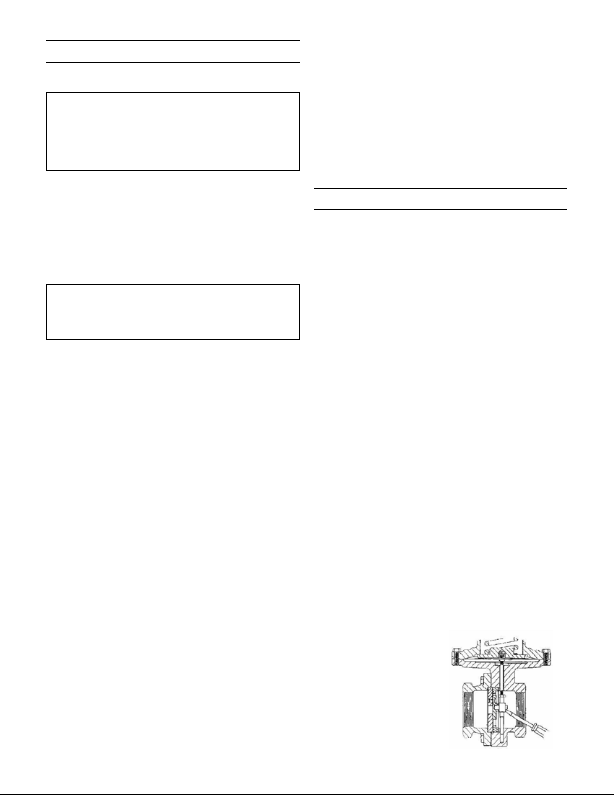
Check the orice alignment of the disc and plate 3.
by releasing the compression of the range spring
and then stroking the valve fully upwards. (To stroke
valve upwards, pry the disc pin upwards with a
screwdriver through the inlet of the valve -- see gure on next page.) In this position, the orices of
the disc and plate must be fully open and in perfect
alignment. If the orices are not aligned, the disc
pin has probably been rotated. Remove the disc and
plate assembly and rotate the disc pin to raise it or
lower it for proper alignment.
If further adjustment of the disc pin does not pro-4.
vide perfect alignment, proceed to VALVE STROKE
ADJUSTMENT.
B. ASSEMBLY AND STROKE ADJUSTMENT
The valve stroke adjustment is determined by how 1.
far the diaphragm assembly is screwed onto the
stem. Hold the disc pin with an open end wrench
and screw the diaphragm assembly onto the valve
stem all the way, and back off two turns initially.
To check the stroke adjustment, put the pressure 2.
ring, valve disc, and valve plate in position in the
valve body, using the same precautions outlined under VALVE SEATS.
Secure the spring housing to the valve body with 3.
two spring housing bolts and tighten.
Using a small screw-4.
driver through the
upstream opening of
the valve body, stroke
the valve against the
upper travel stop of
the spring housing.
The orices should
be aligned in the full
open position.
-2-
Page 3

If the orices are not aligned in the open position, 5.
remove the spring housing and rotate the diaphragm
assembly counterclockwise to lower the disc, and
clockwise to raise the disc.
A further check on the stroke adjustment can be 6.
made by checking the orices in the closed position.
This is a “normally closed” valve, and there should
be a 1/32” overlap when the diaphragm assembly is
down against the valve body.
Remove the valve plate and the valve disc to elimi-7.
nate the possibility of damage during the topworks
reassembly.
Reassemble the adjusting spring and spring seat.8.
Before replacing the spring housing, make certain 9.
that the diaphragm is centered in the body recess.
This recess aligns the spring housing and diaphragm.
In replacing the spring housing, make certain that it 10.
seats properly in the valve body recess.
Replace the spring housing bolts and tighten only n-11.
ger tight. Thread the adjusting screw into the spring
housing until the seats are in their fully closed position. Tighten the spring housing bolts to the torque
values shown on the last page of this document.
Replace the pressure ring, disc, plate, and cap. 12.
See last page of this document for recommended
torque.
Disc Pin and Stem
Valve disc may not be moving freely; inspect and
clean.
Moving parts may be binding; inspect and realign or
replace if necessary.
If Valve Will Not Operate:
Diaphragm may be ruptured and require replace-
ment.
Adjusting spring may be broken and require re-
placement.
Spring may be set improperly and require resetting.
Torque Values
Torque for Valve Cap to Valve Body Bolts
Cast Iron or Bronze 140 in/lbs
Ductile Iron, Carbon Steel or
Stainless Steel
Torque for Spring Housing Bolts
170 in/lbs
5
3
2
4
1
6
7
2
6
200 in/lbs
3
5
1
8
4
Remove the valve disc and valve plate as explained 1.
under VALVE SEATS.
Remove the diaphragm and topworks as described 2.
under DIAPHRAGM REPLACEMENT.
Hold the disc pin with an open end wrench and loos-3.
en the locknut. Now the stem may be unscrewed
from the disc pin and removed.
To reassemble, rst insert the disc pin into the valve 4.
body; followed by the stem and locknut. Screw the
stem into the disc pin about 1/4” or midway on the
stem threads and lock the locknut against the disc
pin.
To reassemble the diaphragm and topworks and 5.
valve seats, refer to the reassembly instructions
under VALVE SEATS and DIAPHRAGM REPLACEMENT.
Troubleshooting
If You Experience Erratic Control:
Oversizing causes cycling and hunting, and reduces
the rangeability of the valve. Make certain that your
sizing is correct.
Excessive foreign matter may be on seats; clean
seats.
Valve stroke may be out of adjustment; readjust and
tighten locknuts securely.
6 bolts
(or multiples)
8 bolts
(or multiples)
Ordering Spare Parts
Use only genuine Jordan Valve parts to keep your valve
in good working order. So we can supply the parts, which
were designed for your valve, we must know exactly which
product you are using. The only guarantee to getting the
correct replacement parts is to provide your Jordan Representative with the valve serial number. This number is
located on the valve identication tag. If the serial number
is not available, the parts needed for your valve might be
determined using the following information: Model number, Valve Body size, Plug Material and Seat Size, Spring
Range or Set Point, Trim Material, Part Name - Number
and Quantity (see parts list chart).
Note: Without a valve serial number, any parts ordered
incorrectly are subject to a minimum 25% restock charge
when returned.
-3-
Page 4

Illustration and Parts List
15
11
10
19
20
Item Description Qty.
21
17
1 Body 1
2 Cap 1
3 Cap Bolt 8
4* Disc Pin 1
14
16
5* Stem 1
6* Locknut 1
7* Plate 1
8* Disc 1
1213
9* Pressure Ring 1
10* Guide Screws 2
11 Lower Diaphragm Plate 1
12* Diaphragm 1
13 Upper Diaphragm Plate 1
14 Spring Housing 1
3
5
15 Spring Housing Bolt 12
16 Range Spring A.R.
1
9
17 Spring Seat 1
19 Adjusting Screw 1
20 Jam Nut 1
6
8
4
21 Name Plate 1
* Recommended Spare Parts
7
2
Bulletin IM-MK501/502-0510
3170 Wasson Road • Cincinnati, OH 45209 USA
Phone 513-533-5600 • Fax 513-871-0105
info@richardsind.com • www.jordanvalve.com
 Loading...