

Page 1
I & M Mark 44
3170 Wasson Road • Cincinnati, OH 45209 USA
Phone 513-533-5600 • Fax 513-871-0105
info@richardsind.com • www.jordanvalve.com
Warning: Jordan Valve Regulators and Control Valves must only be used, installed and repaired in accordance with
these Installation & Maintenance Instructions. Observe all applicable public and company codes and regulations. In the
event of leakage or other malfunction, call a qualied service person; continued operation may cause system failure or
a general hazard. Before servicing any valve, disconnect, shut off, or bypass all pressurized uid. Before disassembling
a valve, be sure to release all spring tension.
Please read these instructions carefully!
Your Jordan Valve product will provide you with long, trouble-free service if it is correctly installed and maintained.
Spending a few minutes now reading these instructions
can save hours of trouble and downtime later. When making repairs, use only genuine Jordan Valve parts, available
for immediate shipment from the factory.
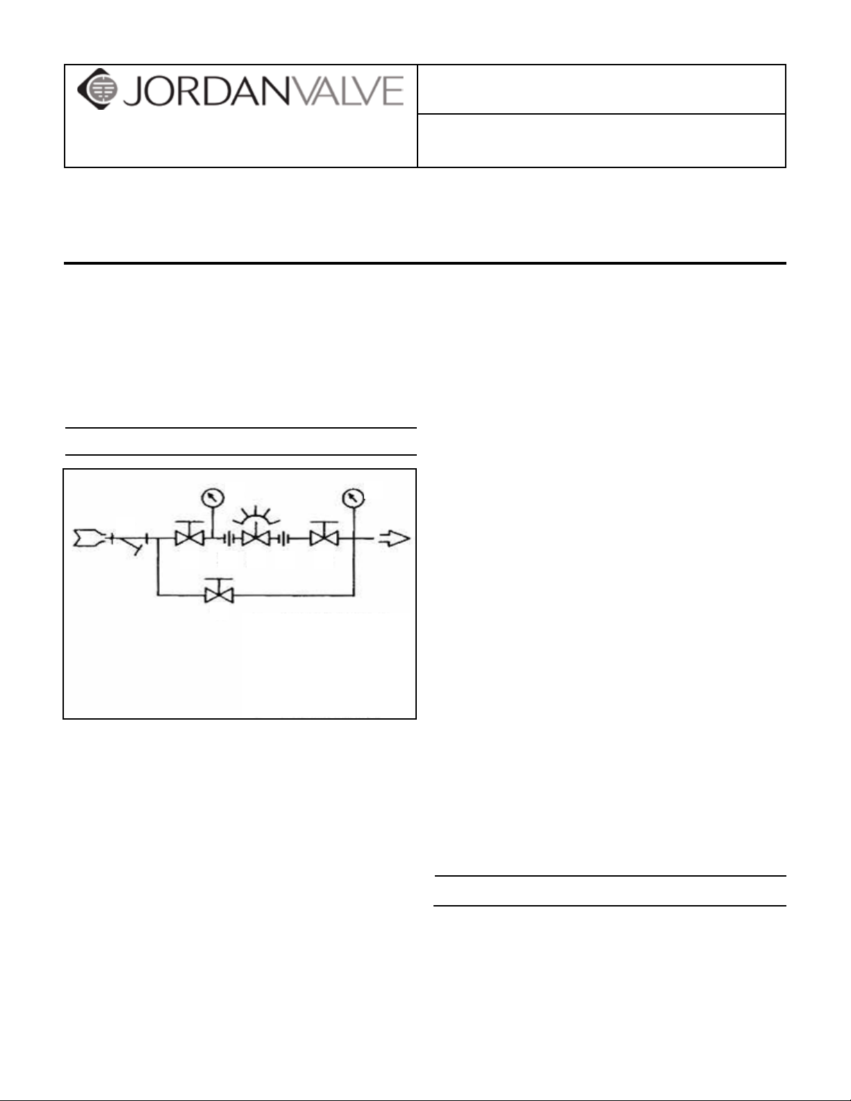
Installation
4
3
5
21
1
1. Shut-Off Valve
2. Pipe Union
3. Strainer
4. Pressure Gauge
5. Jordan MK44
To protect the valve from grit, scale, thread chips 1.
and other foreign matter, all pipe lines and piping
should be blown out and thoroughly cleaned before
the valve is installed.
Shut-off valves, pressure gauges and bypass piping 2.
should be installed as indicated in the diagram to
provide easier adjustment, operation, and testing.
In preparing threaded pipe connections, care 3.
should be exercised to prevent pipe sealing compound from getting into the pipe lines. Pipe sealing
compound should be used sparingly leaving the two
end threads clean. Jordan uses, and recommends,
Teon tape.
A line strainer should be installed on the inlet side of 4.
the regulator to protect it from grit, scale and other
foreign matter. A 0.033 perforated screen is usually
suitable. Line strainers are available for immediate
shipment from Jordan Valve.
12
4
Installation & Maintenance Instructions for
Mark 44 Adjustable Cam Valve
The ow arrow on the valve body must be pointed in 5.
the direction of the ow. The valve may be installed
in any position. The motor arm may be located on
either side of the body. Refer to the “Maintenance”
portion for correct bolt torques.
The motor arm position may be adjusted in 30° in-6.
crements relative to the rocker. Adjust to suit by removing the slotted nut (30) and washer (25). Then
separate the motor arm from the pins in the rocker
(23) and reposition it on the pins to suit. Replace the
parts in reverse order and tighten the nut as tight as
possible, without binding it to the shaft.
Operate the valve within its rated pressure and tem-7.
perature limits, which are on the valve nameplate,
along with materials of construction.
The rotation of the valve may be clockwise or coun-8.
terclockwise to open. This is controlled by the adjustment of the nineteen (19) set screws (24) on the
top of the rocker. The screws must be adjusted in
progressive steps to cause the rotation of the rocker
to stroke the valve. If too large a difference in adjustment between successive screws is attempted
the valve may be difcult or impossible to stroke. It
is not necessary to utilize the full valve stroke. The
adjustability feature allows customizing of the valve
operating characteristic to suit your needs.
The motor arm must be connected to the mecha-9.
nism that will drive the valve. The motor arm travel is
limited to 72° by two set screws (32) threaded into
the angle bracket (7). Be sure that your mechanism
is adjusted so that it does not try to drive the valve
past the stops and cause damage.
The Jordan MK44 valve is not a tight shut-off device. 10.
Other valve means must be provided to insure ow
shutoff.
Trouble Shooting
If the operate lever is difcult to operate:
Slotted nut (30) adjusted too tight. Readjust.
Set screws (24) are improperly adjusted. Adjust for
smooth operation. Do not attempt to make large
changes between adjacent screws.
Defective bearing (13). Replace.
Stem (4) binding in bonnet or seat. Inspect, repair,
Page 2
or replace.
Stem O-Ring Replacement
If there is external leakage:
Stem or bonnet o-ring (9) or (5) defective. Replace.
Maintenance
Routine maintenance should be expected due to normal wear and tear, damage from external sources or debris. The regulator components, especially the moving
and sealing parts, should be inspected periodically and
replaced as necessary. Frequency of inspection/replacement depends upon severity of conditions, but may also
be required by local/state/federal law or industry standards.
Warning: Be sure that there is no pressure in the
valve before loosening any ttings or joints. The
following steps are recommended.
Close inlet shut-off valve and by-pass valve.1.
Allow pressure to bleed off through the downstream 2.
piping.
When pressure gauge indicates that there is no pres-3.
sure in the valve, it may be serviced or removed.
Refer to the drawing for proper orientation of parts and
nomenclature.
Body/Bonnet O-Ring
Remove all pressure from the line as outlined in 1.
“Warning” above.
Remove the low ow end stop set screw (32) and 2.
rotate the rocker (23) to disengage the stroke stop
bearing (13).
Remove the four (4) cap screws (8) and lift the bon-3.
net (6) off of the body (1).
Remove the o-ring and clean the mating surfaces on 4.
the body and bonnet. Inspect these surfaces for any
scratches or defects that could cause seal leakage.
Lubricate the new o-ring with DOW CORNING #4 or 5.
any other lubricant that is suitable for use with the
o-ring material and your product at your operating
temperature.
It is strongly recommended that the stem o-ring (9) 6.
also be replaced if the valve has been disassembled.
If you are going to replace it, proceed to section B,
step 4, otherwise go on to step 7 below.
Remove the seat from the body and place it over the 7.
end of the stem. Hold the bonnet upright and take
the body and place it over the bonnet and install the
bonnet into the body. Continue the reassembly of
the valve in the reverse order that you disassembled
it and then torque the cap screws according to the
“Torque Procedure” at the end of this manual.
Remove all pressure from the line as outlined in 1.
“Warning” under the Maintenance Section.
Remove the low ow end stop set screw (32) and 2.
rotate the rocker (23) to disengage the stroke stop
bearing (13).
Remove the four (4) cap screws (8) and lift the bon-3.
net (6) off of the body (1).
Using a blunt pin punch, drive out the roll pin (15) 4.
and thread the stroke stop (12) off of the stem (4).
Push the threaded end of the stem into the bonnet 5.
and remove the stem from the cage end of the bonnet. (The cage end is the portion of the bonnet that
is normally in the body).
Remove the o-ring, and clean the stem and the bore 6.
in the bonnet where the o-ring operates. Inspect
the bore for any scratches that might damage the
o-ring.
Lubricate the new o-ring with DOW CORNING #4 or 7.
any other lubricant that is suitable for use with the
o-ring material and your product at your operating
temperature.
Install the o-ring onto the stem from the threaded 8.
end so that the stem ow prole does not cut the
o-ring.
Carefully reinstall the stem back into the bonnet 9.
from the cage end.
Remove the seat from the body and place it over the 10.
end of the stem. Hold the bonnet upright and take
the body and place it over the bonnet and install the
bonnet into the body. Continue the reassembly of
the valve in the reverse order that you disassembled
it and then torque the cap screws according to the
Torque Procedure Section.
Seat or Seal Replacement
If the seat or stem is to be replaced it is strongly rec-1.
ommended that the body/bonnet o-ring and stem
o-ring be replaced also. Therefore follow step A to
replace both o-rings.
While the stem is out of the bonnet, remove the re-2.
taining ring and install it onto the new stem. Otherwise follow the steps in A.
Bearing (Stroke Stop) Replacement
Remove all pressure from the line as outlined in 1.
“Warning” under the Maintenance Section.
Remove the low ow end stop set screw (32) and 2.
rotate the rocker (23) to disengage the stroke stop
bearing (13).
Using a blunt pin punch, drive the roll pin (15) out of 3.
the bearing (13).
Replace the bearing and reassemble in reverse or-4.
der.
-2-
Page 3

Rocker Plates, Etc.
Ordering Spare Parts
Remove all pressure from the line as outlined in 1.
“Warning” under the Maintenance Section.
Remove the low ow end stop set screw (32) and 2.
rotate the rocker (23) to disengage the stroke stop
bearing (13).
Remove the cotter pin (31), slotted nut (30), and 3.
washer (25). Remove the rocker from the support
stud (26).
The sub-assembly containing the rocker plates, and 4.
support straps (16) & (20) can now be removed from
the rocker and the necessary parts replaced.
Reassemble in reverse order.5.
Bearing (Rocker) Replacement
Remove all pressure from the line as outlined in 1.
“Warning” under the Maintenance Section.
Remove the low ow end stop set screw (32) and 2.
rotate the rocker (23) to disengage the stroke stop
bearing (13).
Remove the cotter pin (31), slotted nut (30), and 3.
washer (25) and remove the rocker from the support stud (26).
Press the bearing out of the rocker. A .75” diameter 4.
shaft will be helpful.
Press the new bearing into the rocker and then reas-5.
semble in reverse order.
Use only genuine Jordan Valve parts to keep your valve
in good working order. So we can supply the parts, which
were designed for your valve, we must know exactly which
product you are using. The only guarantee to getting the
correct replacement parts is to provide your Jordan Representative with the valve serial number. This number is
located on the valve identication tag. If the serial number
is not available, the parts needed for your valve might be
determined using the following information: Model number, Valve Body size, Plug Material and Seat Size, Spring
Range or Set Point, Trim Material, Part Name - Number
and Quantity (see parts list chart).
Note: Without a valve serial number, any parts ordered
incorrectly are subject to a minimum 25% restock charge
when returned.
Torque Procedure
Caution: Do not over-tighten cap screws.
Install all cap screws hand tight.1.
Tighten in the order of the pattern shown below to 2.
75-100 in/lbs., (6-8 ft./lbs.) then repeat to 140 in/
lbs. (12 ft/lbs.).
-3-
Page 4

Illustration and Parts List
24
13
23
12
10
30
7
4
3
2
28
11
14
Item Description Qty. Material
1 Body 1 Bronze
15
2 Seat 1 Brass
3 Retaining Ring 1 Stainless Steel
9
4 Stem / Plug 1 Stainless Steel
5 O-Ring 1 Viton
5
6 Bonnet 1 Brass
7 Angle 1 Steel
8
31
8 Cap Screws 4 Alloy Steel
9 O-Ring (Stem) 1 Viton
6
26
10 Spring 1 Steel
11 Guide Pin 1 Steel
27
25
29
12 Stroke Stop 1 Steel (KI Plated)
13 Ball Bearing 1 Steel
14 Roll Pin (Bearing) 1 410 SST
15 Roll Pin (Stem) 1 410 SST
1
16 Lower Support Strap 1 Steel
17 Rocker Plates 20 Steel
18 End Plates 2 Steel
19 Wire 8” Music Wire
22
20
18
19
17
20 Upper Support Strap 1 Steel
21 Drive Screws 8 Aluminum
22 Guide Rods 2 Steel
23 Rocker 1 Cast Iron
24 Set Screws 19 Alloy Steel
21
16
25 Washer 2 Steel
26 Support Stud 1 Steel
27 Flanged Bearing 1 Oilite Bronze
28 Motor Arm 1 Steel
29 Dowell Pins 2 Steel
30 Slotted Nut 1 Steel
32
31 Cotter Pin 1 Steel
32 Stop Screws 2 Alloy Steel
Bulletin IM-MK44-0410
3170 Wasson Road • Cincinnati, OH 45209 USA
Phone 513-533-5600 • Fax 513-871-0105
info@richardsind.com • www.jordanvalve.com
 Loading...