

Page 1

I & M Mark 4150 and 4160 Series
3170 Wasson Road • Cincinnati, OH 45209
Phone 513.533.5600 • Fax 513.871.0105 (f)
info@richardsind.com • www.jordanvalve.com
Warning: Jordan Valve Control Valves must only be used, installed and repaired in accordance with these Installation & Maintenance Instructions. Observe all applicable public and company codes and regulations. In the event
of leakage or other malfunction, call a qualified service person; continued operation may cause system failure or
a general hazard. Before servicing any valve, disconnect, shut off, or bypass all pressurized fluid. Before disassembling a valve, be sure to release all spring tension.
IntroductIon
The Mark 4150 and 4160 Series pressure controllers
are designed to provide years of reliable and accurate
service.
These instructions cover maintenance, adjustment,
and changes in mode of control.
Installation & Maintenance Instructions for the
Mark 4150 and 4160 Series Pressure Controllers
If the body is flanged, the bolts should be tightened up
evenly to reduce risk of damage to the valve body and
the flange.
A good quality thread lubricating compound should be
used on all male connections if the body has screwed
connections.
Control Line Connectors
These instructions are intended for the controllers
in general. Any instructions that apply to specific
controllers will be indicated by model number in the
instruction.
Model numbers are stamped on the nameplate located inside the cover of the controller (Key 29, Figure 4).
The connections should be made in an area of the
pipeline that is free of bends and elbows. Piping
connections should be made with 1/4” or 3/8” pipe or
tubing.
Tap the pipeline as close to the valve body as possible
allowing for these limiting factors.
Controllers
Inspect the controllers for shipping damage and foreign debris when uncrating.
Valve
Ensure the pipeline is free of welding slag, chips and
other debris by blowing out the line prior to installation.
It is recommended that a strainer be installed up
stream of the valve to protect the valve from foreign
debris in the line. Jordan Valve recommends a standard three-valve maintenance bypass be installed.
This allows isolation of the control valve without shutting down the pipeline system.
The valve should be positioned on the line so the flow
direction indicator corresponds to the direction of the
flow of the pipeline.
1. The tap area should be an area that is free
from abnormal velocities.
2. The ideal distance away from the body should
be 10 x the pipeline diameter.
The control pressure line is run from the tapped hole in
the side or the back of the case to the main pipeline.
Install a lock shield needle valve in the control line to
slow down the controlled pressure or to dampen out
any pulsations. While the control valve is operational,
the needle valve must never be entirely closed.
An air vent is provided on all controllers and works well
when air is used as the operating medium. When gas
is used the vent can be removed, this allows for an additional 1/4” NPT connection for gas to be piped away.
Page 2
Mark 4150 and 4160 SerieS PreSSure ControllerS
Operation
Although the output for these controllers are set prior
to shipping, upon arrival the following items should be
checked.
Bellofram Mark 50 Filter Regulator
Bellofram Mark 50 Filter Regulator is a self-contained
filter regulator designed to deliver air or gas to the
pilot at a constant pressure. The Bellofram Mark 50 is
designed to handle inlet pressures up to 250 psi. The
Series 4150/4160 delivers an outlet pressure of 3 - 15
psi when the regulator is set to 20 and it will deliver 6-30
psi output when the regulator is set to 35 psi.
The filter component ensures that operation is clean and
dry.
The relief valve is geared to open when the pressure is
reduced to 1 psi above the regulator set point.
Releasing the lock nut and adjusting the adjusting screw
located on the top of the regulator can reduce pressure
setting for the regulator.
Proportional Controllers
Most of the proportional controls will be used in applications that require a band set to approximately 15%. The
following steps are used to test this setting.
1. The air supply should be connected to Bello-
fram Mark 50 filter regulator.
2. Zero the pressure setting dial.
3. Set the proportional band adjustment to 15%
4. There should be no pressure sent to the mea
suring element.
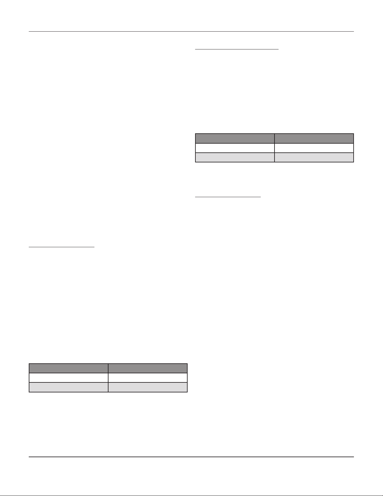
5. For direct or reverse acting controllers the
range and output should be set as follows.
Range Output
3-15 psi 8-10 psi
6-30 psi 16-20 psi
Proportional-Reset Controllers
1. The reset dial should be set to maximum.
2. The air supply should be connected to Bello-
fram Mark 50 filter regulator.
3. Zero the pressure setting dial and proportioned
setting dial.
4. There should be no pressure sent to the mea-
suring element.
5. For direct or reverse acting controllers the
range and output should be as follows.
Range Output
3-15 psi 8-10 psi
6-30 psi 16-20 psi
Start Up
Proportional Controllers
1. The air supply should be connected to Bellofram
Mark 50 filter regulator.
2. Connect the control pressure line and open the
lock shield needle valve.
3. Ensure all piping and connections are free from
leaks.
4. Set the pressure to the desired control point.
5. Proportional band should be set at 15% of the
bandwidth.
6. Open the manual control valves that are up
stream and downstream, at the same time close
the by-pass valves.
7. Set the controller near the desired control point.
When it reaches that point, begin to broaden the
proportional band. Broaden the band as little
as possible. The narrowest band that
will not result in cycling provides
the best control. This band adjustment
will affect the zero. Re-zero the unit.
8. Test the bandwidth by changing the pressure
setting adjustment for a moment. If this
causes cycling, then broaden the proportional
band and test again. This procedure is
to be repeated until stability is reached.
-2-
Page 3
Mark 4150 and 4160 SerieS PreSSure ControllerS
Proportional-Reset Controllers
1. The air supply should be connected to Bellofram
Mark 50 filter regulator.
2. Connect the control pressure line and open the
lock shield needle valve.
3. Ensure all piping and connections are free from
leaks.
4. Set pressure to the desired control point.
5. Proportional band should be set at 100% of
bandwidth.
6. Maximize the setting on the reset dial.
7. Open the manual control valves that are up
stream and downstream, at the same time close
by-pass valves.
8. Set the controller near the desired control point.
When it reaches that point, begin to narrow
the proportional band until a cycling condition
exists. Broaden the band slightly until a stable
condition is reached. There is no need
to reset the zero in controllers that have reset.
9. Try to obtain the fastest reset time without intro
ducing cycling control carefully by adjusting the
reset rate.
10. Test the bandwidth and the reset rate by chang-
ing the pressure setting adjustment for
a moment. If this causes cycling, then broaden
the proportional band and test again. This
procedure is to be repeated until stability is
reached.
Example: with the proportional band set @ 1 (10%),
using a Bourdon tube of 0-1000 psi that is set @ 500 psi
on the pressure dial. The full travel of the valve would
occur between 450 psi (3 psi output) and 550 psi (15 psi
output) to try to maintain the set point.
Using this theory, an input pressure of 500 would give
you an output pressure of 9 psi. The greater the proportional band setting is the slower the reaction.
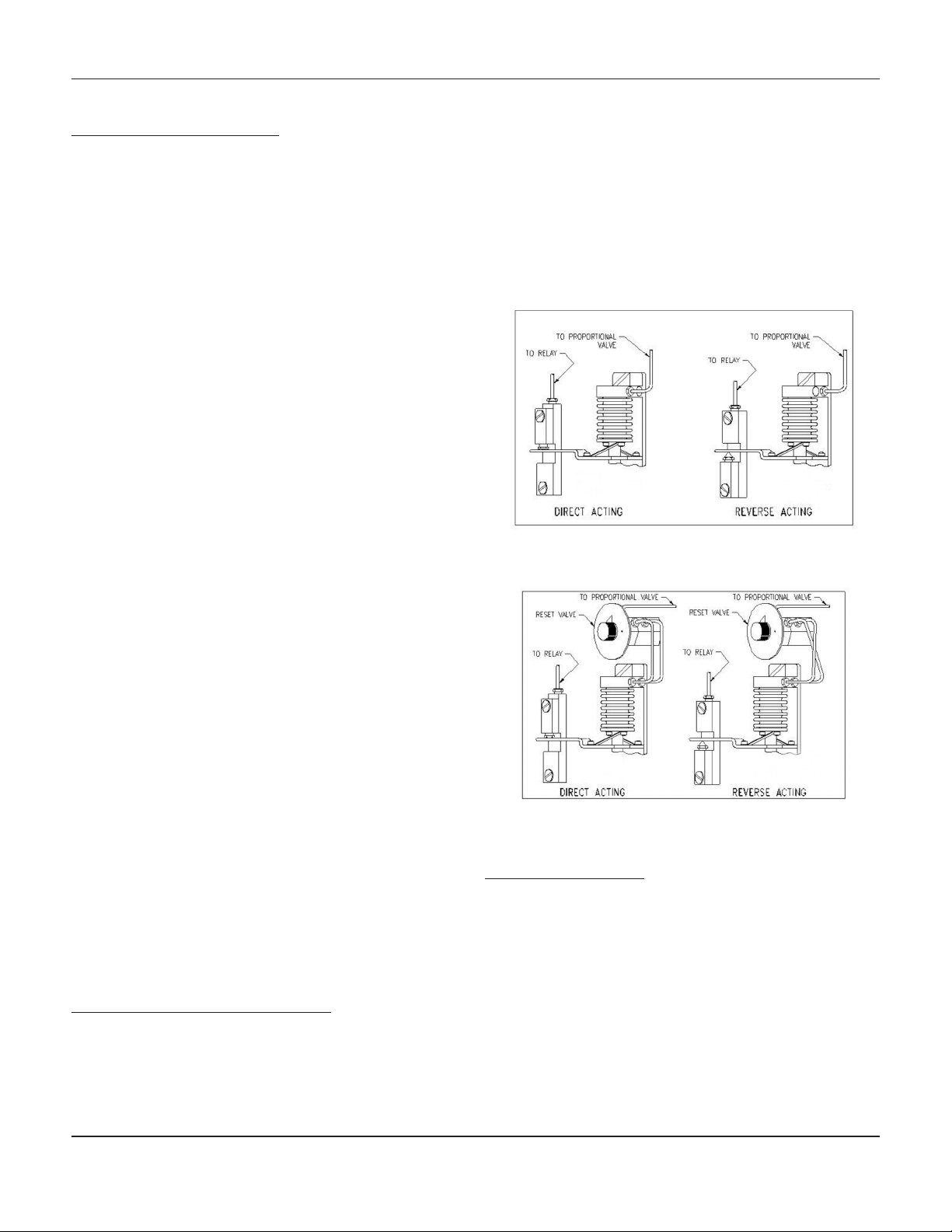
Figure 1: Pressure Connections for
Proportional Controller
The goal for the controller setting is to have the narrowest proportional band and the fastest reset rate that will
not cause cycling.
Changing Controller Action
One advantage of the Mark 4150/4160 is the ease at
which you can change from one mode of control to another. There is a connection for both direct and reverse
action in all modes of control. There is also a screw (key
5, figure 6) provided to plug the hole opposite of the
nozzle. It will be necessary to follow INITIAL SETTINGS
after any change in mode of control.
Adjustments
Proportional Band Width Adjustments
The proportional band width adjustment determines the
change in control pressure required to cause the control
valve to travel full open or full closed.
Figure 2: Pressure Connections for
Proportional-Reset Controller
Reset Rate Adjustment
By definition the reset rate is the number of minutes that
it takes to adjust the controller to adjust the output pressure up or down by the same amount of proportional
change output caused by the process change.
The reset rate is calibrated in minute per repeat.
-3-
Page 4
Mark 4150 and 4160 SerieS PreSSure ControllerS
Pressure Setting Adjustment
The Mark 4150 and 4160 come with calibrated set point
adjustment. The dial is calibrated for pressure ratings
of the measurement element. If start up instructions are
followed, the pressure setting dial is correct for any settings on proportional-reset controllers.
Mark 4150 Pressure Controller
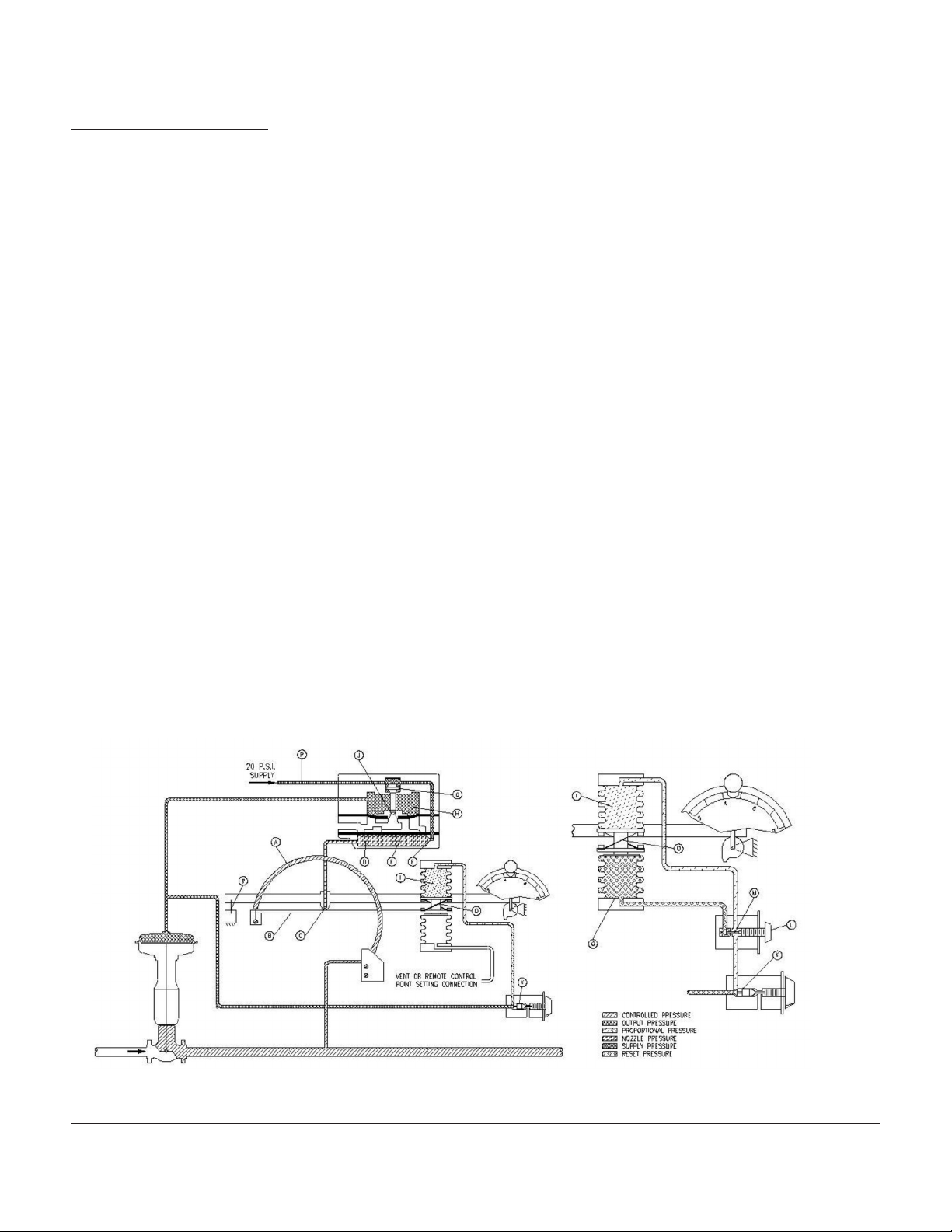
The theory of operation can be broken down into steps.
Refer to the schematic diagram figure 3.
I. The pressure first enters the Bourdon tube. As
the pressure increases the Bourdon tube
straightens causing the beam (B) attached to
the end of the Bourdon tube to move closer to
nozzle (C).
2. Closing the nozzle (C) will cause a build up of
pressure in chamber (D) from the constant air or
gas supply through the orifice (E).
3. The resulting pressure built up in chamber (D)
cause the diaphragm (F) to push up and
open valve (G).
4. An open Valve (G) will cause the constant air or
gas supply to flow into chamber (H).
5. The build up of pressure in chamber (H) causes
diaphragm (F) to be pushed back to its original
position and therefore closes valve (G).
6. The increase in pressure in chamber (H) sends
the supply pressure to flow to the diaphragm
of the control valve causing the control valve to
start to close.
7. At the same time, the pressure flows through the
three-way valve (K) causing an increase in pres
sure in bellows (I).
8. The increase in the pressure bellows (I) cause
the beam (B) to move away from nozzle (C). As
a result there will no longer be a build up of
pressure in (D). The control valve is now at the
desired pressure setting.
If there is a decrease in control pressure the above mentioned steps will proceed in reverse. The control pressure will bleed out through the exhaust vent (J).
Please note that the changes in pressure are continuous
in nature. The process has been explained in steps for
ease of explanation.
As seen in the figure 3, schematic illustration of Mark
4150, the output pressure from relay chamber (H) goes
to both the proportional band adjustment relay three-way
valve (K) and the control valve diaphragm. The amount
of feedback to the proportional bellows (I) can be adjusted by adjusting the orifice. If valve (K) is fully open,
then the total of the diaphragm pressure is sent to the
bellows chamber (I).
This causes the beam (B) to move away from nozzle (C)
allowing the pressure to be released from chamber (D).
The result of this is 100% proportional band based on
the rating of the Bourdon tube. Closing the three-way
valve (K) will result in a lowering of proportional band response. The proportional band would be approximately
3% when fully closed.
Figure 3: Schematic Illustration of
Mark 4150 Proportional Controller
-4-
Schematic Illustration of Mark 4150
Proportional-Reset Controller
Page 5

Mark 4150 and 4160 SerieS PreSSure ControllerS
Mark 4160 Pressure Controller
The operation of Mark 4160 - proportional-reset controller, is the same as the Mark 4150 with the addition of a
reset rate adjustment (L). Follow steps 1-6 from operation of the 4150 then proceed with the following:
1. In step No. 7, for the Mark 4160 the pressure will
flow through the three-way valve (K), to reset
valve (M) where a portion of pressure
will be diverted to the bellows (O).
2. The pressure will be built up in bellows (O)
pushing beam (B) to nozzle (C) and therefore
increased pressure to valve and to bellows (I).
This process will continue until control pressure
is equal to the set point.
3. The proportional bandwidth determines how
much the pressure will deviate from the
set point. The reset determines the amount of
time the deviation is away from the set point.
MaIntenance
The Mark 4150/4160 Series Bourdon Tubes can be
replaced. They may be replaced due to changes in
pressure regulations or for maintenance.
Replacing Bourdon Tube
(Refer to Figure 6)
1. Detach the connecting link and bearing (Key 37)
from the beam.
2. Unscrew the two fixing screws (Key 8) holding
the tube. Detach tube from the sub-assembly.
3. Replace the Bourdon tube by removing the con-
necting link and bearing from the exist
ing tube. Attach the connecting link and
bearing on the new Bourdon tube.
4. Zero the pressure dial.
5. Install the Bourdon tube in the sub-assembly.
Reconnect the connecting link and bearing to
the beam.
6. Ensure that the tube is in a horizontal position
and that there is tension in the connect
ing link. The tension can be adjusted by bend-
ing the cross springs (Key 28).
7. Adjust and calibrate for start-up.
Two steps should be carried out in regular scheduled
maintenance. A cleaner button allows you to clean the
passages in the relay orifice. This button should be
pushed regularly. The second step is using the drain
cock that is located on the underside of the drip well in
the Mark 50 filter. This drip well, should be allowed to
bleed off to atmosphere to prevent moisture from contaminating the controller.
trouble ShootIng
1. The control valve continually cycling or hunting.
1.1. The constant cycling of a controller can
occur if the reset rate is set too
fast or the band setting is set too narrow.
1.2. Ensure that the controller valve plug is
not sticking.
1.3. A control valve always operating near its
seat will indicate an oversized control
valve.
2. Incomplete Pressure Change on the Diaphragm.
2.1. Ensure an accurate reading is being
displayed from the diaphragm pressure
gauge.
2.2. Verify that lines and connections are free
from leaks.
Replacing Bellows
(Refer to Figure 6)
1. Detach sub-assembly from controller.
2. Remove the connecting link and bearing (Key
37) from the beam.
3. Remove the bellows unit from the frame (Key 16)
4. Install the bellows in the control assembly. Begin
by ensuring that the beam is horizontal and with
the pressure setting dial at zero.
Then attach the connecting link and the bearing
link to bellows and beam. Ensure that there is
tension on the connecting link. Tension
can be added by bending the cross springs
(Key 28).
5. Adjust and calibrate for start up.
Calibration of Controllers
1. Move the calibration adjuster (Key 30, Figure 6)
to the right or the left.
2. Repeat the nozzle adjustment and step 5 for
proportional controller or step 6 for proportional-
reset controller.
3. To release the calibration adjuster, loosen the
two screws, above and below the beam,
to the left of the nozzle.
-5-
Page 6

Mark 4150 and 4160 SerieS PreSSure ControllerS
Calibrate Zero on Proportional Controllers
1. Depending on the controller type the supply
pressure will be 20 or 35 psi. Attach a suitable
pressure gauge to the output pressure.
2. Connect the pressure source to the pressure
block and set the proportional bandwidth to 15%
(1.5).
3. Zero the pressure setting dial.
4. Raise or lower the nozzle (Key 34, Figure 6)
to get the desired setting of zero as per chart
below. Nylon insert will hold the nozzle in place.
5. Allow maximum pressure to the measuring ele-
ment. Set the pressure dial to maximum. Output
pressure should comply with the zero setting
column in the following table, if not go to
Note 1.
Control
Action
Direct 3-15 psi 20 psi 8-10 psi
Direct 6-30 psi 35 psi 16-20 psi
Reverse 15-3 psi 20 psi 8-10 psi
Reverse 30-6 psi 35 psi 16-20 psi
Output
Range
Supply
Pressure
Zero
Setting
Note 1 - These steps are to be used if the zero setting
pressure or output range is not obtained when maximum
pressure is applied to the measuring element.
1. Move the calibration adjuster (Key 30, Figure 6)
to the right or the left.
2. Repeat the nozzle adjustment and Step 5 for
proportional controller, or Step 6 for proportional reset controller.
3. To release the calibration adjuster, loosen two
screws, above and below the beam, to the left of
the nozzle.
Control
Action
Direct 3-15 psi 20 psi 8-10 psi
Direct 6-30 psi 35 psi 16-20 psi
Reverse 15-3 psi 20 psi 8-10 psi
Reverse 30-6 psi 35 psi 16-20 psi
Output
Range
Supply
Pressure
Zero
Setting
Calibrate Zero on Proportional- Reset
Controllers
1. Depending on the controller type the supply
pressure will be 20 or 35 psi. Attach a suitable
pressure gauge to the output pressure.
2. Connect the pressure source to pressure block
and set the proportional bandwidth to zero.
3. Set the reset dial to .005 minutes per repeat.
4. Zero the pressure setting dial.
5. Raise or lower the nozzle (Key 34, Figure 6) to
get the desired setting of zero as per
chart below. Nylon insert will hold the nozzle in
place.
6. Allowing maximum pressure to the measuring
element. Set the pressure dial to maximum. Out-
put pressure should comply with the zero setting
column in the following table, if not go to Note 1.
Changing of Controller Output
Controllers having an output range of 3-15 psi, can be
converted to having an output range of 6-30 psi. This
can be done by changing the two color coded control
bellows. The green bellows is for 3-15 range, and yellow
bellows for 6-30 psi range.
When the pressure range is changed, it is necessary to
change the pressure gauges. This can be completed
by unscrewing the old pressure gauges from their boss
and screwing in the new gauges.
-6-
Page 7

aSSeMbly
Mark 4150 and 4160 SerieS PreSSure ControllerS
Figure 4: Mark 4150 Proportional Pressure Controller with
Bourdon Tube Measuring Element
PartS reference
Figure 5: Partial view of Mark 4160
Pressure Controller Showing the Reset
Valve and the Arrangement of Tubing
-7-
Page 8

Mark 4150 and 4160 SerieS PreSSure ControllerS
Controller Main Assembly (Refer to Figures 4 and 5)
Key
No.
1 1H2889 Spring Washer Steel Cd. Pl
2 1H2891 Groove Pin Aluminum
3 1H2886 Cover Latch Steel Cd. Pl
4
5*
6 367X3 Proportional Band Adj.
7 1H2890 Groove Pin Aluminum
8 1C8937 Screen and Elbow Assy Sub-Assy
9* 1C3286 Cont. Pres. Block
10*
11* 0T0191 Glass Gasket, 2 Req’d Neoprene
12 1A4658 Retaining Ring, 2 Req’d Galv, Steel
13 1A5120 Screw, 8 Req’d Steel Cd. Pl
14* 0T0192 Gauge Glass, 2 Req’d Acrylic
15* 1C3762 O-Ring Buna-N
16 1C2256 Lockwasher, 4 Req’d Steel Cd. Pl
17 1C3333 Screw, 4 Req’d Steel Cd. Pl
18 1H2698 Cont. Pres. Block Steel
19 1H3435 Supply Pres. Gauge
20 1H2759 Relay Tubing Assy Copper
21 536X47 Pilot Relay
Part
No.
1H2712 Output Pres. Gauge 30
psi.
1H3048 Output Pres. Gauge
60 psi
1H2753 Compensator Tubing
Assy
1H6864 Compensator Tubing
Assy
1H2966 Reset Tubing Assy Copper
1H6866 Reset Tubing Assy 304 SST
Assy
Gasket
1H2887 Relay Base Gasket Neoprene
1N8737 Relay Base Gasket Hi-
Temp
1H2895 Cont Pres. Block 316 SST
0-30 psi
1H3436 Supply Pres. Gauge
0-60 psi
1H6861 Relay Tubing Assy 304 SST
536X84 Pilot Relay Hi-Temp
Part
Description
Material
Sub-Assy
Sub-Assy
Copper
304 SST
Sub-Assy
Neoprene
Si Rubber
Cd. Pl.
Sub-Assy
Sub-Assy
Key
No.
22 3H2885 Relay Base Zinc
23 1H5269 Screw, 17 Req’d Steel Cd. Pl
24 4H2684 Cover Aluminum
25* 1J24075 Cover Gasket Sponge
26 4H2699 Case Aluminum
27*
28 1C9419 Screw, 2 Req’d Steel Cd. Pl
29 1H2702 Instruction Plate Aluminum/
30 1H2888 Roll Pin, 2 Req’d Steel Cd. Pl
31*
32
33 1A3321 Screw, 6 Req’d Steel Cd Pl
34 536X61 Reset Valve
35*
36*
37 1H5271 Screw, 2 Req’d Steel Cd. Pl
38 1H5270 Screw, 4160 Steel Cd. Pl
39
* Recommended Spare Parts
Part
No.
1C8974 Relay Gasket Neoprene
1N8738 Relay Gasket, Hi-Temp Silicone
1H3013 Cont. Tubing Assy,
4150, 4160
1H4528 Cont. Tubing Assy. Copper
1H3011 Cont. Tubing Assy,
4150, 4160
1H4526 Cont. Tubing Assy. 304 SST
ML536X Cont. Sub-Assy. 4150,
4160
ML536XH Cont. Sub-Assy.
Hi-Temp, 4150, 4160
536X15 Reset Valve, Hi-Temp
1H2755 Compensator Tubing
Assy.
1H6870 Compensator Tubing
Assy.
1H2757 Conpensator Tubing
Assy.
1H6870 Conpensator Tubing
Assy.
1A7675 Pipe Plug Steel
1A7675 Pipe Plug 316 SST
Part
Description
Material
Rubber
Rubber
SST
Copper
304 SST
Sub-Assy.
Sub-Assy.
Copper
304 SST
Copper
304 SST
-8-
Page 9

Mark 4150 and 4160 SerieS PreSSure ControllerS
PartS reference
Figure 6: Controller Sub-Assembly for Bourdon
Tube Controllers Mark 4150 and 4160
Controller Sub Assembly (Refer to Figure 6)
Key
No.
1 1C8969 Screw, 4 Req’d Steel Cd. Pl
2 1B2751 Screw Steel Cd. Pl
3 1C8990 Screw, 4 Req’d Steel Cd. Pl
4 1A5733 Screw, 8 Req’d Steel Cd. Pl
5* 1H2674 Screw Steel Cd. Pl
6* 1H2673 Screw Steel Cd. Pl
7 1H2676 Screw, 2 Req’d Steel Cd. Pl
8 1H2677 Screw, 2 Req’d Steel Cd. Pl
9* 1H2678 Screw, 2 Req’d Steel Cd. Pl
10* 1B2776 Screw, 2 Req’d Steel Cd. Pl
11* 1A3319 Screw, 2 Req’d Steel Cd. Pl
12 1E8730 Washer, 2 Req’d Steel Cd. Pl
13 1H2671 Washer, 2 Req’d Steel Cd. Pl
14* 1H2672 Washer, 2 Req’d Acrylic
15*
16 1H2653 Bellows Frame Aluminum
17
Part
No.
1H2655 Bellows Assy. 3-15 psi,
2 Req’d
1H2680 Bellows Assy. 6-30 psi,
2 Req’d
1H2654 Bellows Frame Gasket Neoprene
1N8735 Bellows Frame Gasket,
Hi-Temp
Part
Description
Material
Si Rubber
Key
No.
18 1D3976 Bellows Screw, 2 Req’d 18-8 SST
19*
20 1H2658 Bellows Stud 18-8 SST
21* 1E2226 O-Ring Buna-N
22 1H2650 Bourdon Tube Mounting
23 2H2651 Mounting Plate Steel
24 536X4 Pressure Adj. Assy.
25 1H2652 Adj. Spacer 2 Req’d Steel
26 1J4234 Rotary Shaft Spring 302 SS
27 1H2659 Spacer Zinc
28 1H2660 Cross Spring, 2 Req’d 304 SS
29 1H2661 Pressure Set Arm Steel
30 2H2662 Calibration Adj. Zinc
31 1U6392 Reversing Block Assy.
32* 1H2664 O-Ring, 3 Req’d Viton
33 16A0976 Nylon Insert Nylon
* Recommended Spare Part
Part
No.
1D3970 Bellows Gasket, 2 Req’d Neoprene
1N8736 Bellows Frame Gasket,
2 Req’d
1N8387 O-Ring, Hi Temp Viton
Bracket
536X8 Zero Adj. Assy.
Part
Description
Material
Si Rubber
Aluminum
-9-
Page 10

Mark 4150 and 4160 SerieS PreSSure ControllerS
Controller Sub Assembly Continued,
Key
No.
34* 1U6391 Nozzle 316 SS
35 1H2668 Beam Steel
36* 1H2669 Flapper Spring Steel
37 1L3796 Connecting Link 316 SS
38 1C8977 Flexure Strip Base Steel, Cd Pl
39 1C8978 Flexure Base Spring Steel
40 1C8975 Flexure Strip Nut, 2 Req’d Steel, Cd Pl
41*
Part
No.
1R8729 Bourdon Tube, 0-30 psi
1R8730 Bourdon Tube, 0-60 psi
1R8731 Bourdon Tube, 0-100 psi
1R8732 Bourdon Tube, 0-200 psi
1R8733 Bourdon Tube, 0-300 psi
1R8734 Bourdon Tube, 0-600 psi
1R8735 Bourdon Tube, 0-1000 psi
1R8736 Bourdon Tube, 0-1500 psi
1R8737 Bourdon Tube, 0-3000 psi
Part
Description
Material
316 SS
42
1R8738 Bourdon Tube, 0-5000 psi
2H2883 Bourdon Tube, 0-8000 psi
2H2884 Bourdon Tube, 0-10000 psi
2H6785 Bourdon Tube, 0-15000 psi
1H3044 Press. Adj. Dial, 0-30 psi
1H3034 Press. Adj. Dial, 0-60 psi
1H3035 Press. Adj. Dial, 0-100 psi
1J5237 Press. Adj. Dial, 0-200 psi
1H3036 Press. Adj. Dial, 0-300 psi
1H3037 Press. Adj. Dial, 0-600 psi
1H3038 Press. Adj. Dial, 0-1000 psi
1H3039 Press. Adj. Dial, 0-1500 psi
1H3040 Press. Adj. Dial, 0-3000 psi
1H3041 Press. Adj. Dial. 0-5000 psi
1H3042 Press. Adj. Dial. 0-8000 psi
1H3043 Press. Adj. Dial. 0-10000 psi
Aluminum
1H3043 Press. Adj. Dial. 0-15000 psi
* Recommended Spare Part
-10-
Page 11

Mark 4150 and 4160 SerieS PreSSure ControllerS
Pilot Relay Assembly
Key
No.
1 1A3319 Screw, 4 Req’d Steel
2 1H2697 Spring Plate Steel
3*
4 0X0836 Valve Plug Spring Inconel
5* 1C8961 Relay Spring Inconel
6* 0Y0617 Valve Plug 316 SS
7 1C9370 Dia. Assy. Temp To 150°F Sub Assy.
8 1L5556 Top Dia., Temp 150°F Buna-N
9* 1C8969 Screw Temp to 150°F 6 Req’d Steel
10* 1D6875 O-Ring Syn. Rubber
11* 1H8266 Restriction Plug Orifice Assy. Sub Assy.
12 1E2303 Core & Wire Assy. Sub Assy.
13 2H2693 Relay Body Zinc
Part
No.
1H2696 Spring Plate Gasket,
Part
Description
Material
Neoprene
Temp. To 150°F
1K7000 Spring Plate Gasket,
Sil. Rubber
Temp. To 150°F-250°F
0Y0617B Brass
1K6996 Dia. Assy. Temp 150°-250°F
1A3294 Screw 150°F-250°F 6 Req’d
MK4150and4160IM/0214/2K
14* 2K4404 Spacer Ring Zinc
15* 1C9369 Diaphragm Case Assy Sub Assy.
1K7001 Bottom Gasket (Not Shown)
16
Temp. 150°F-250°F Sil. Rubber
Figure 7: Exploded View of Pilot Relay
used in Mark 4150 and
4160 Controllers
1K7002 Top Gasket, Temp 150°-250°F
17 1P8261 Washer, 6 Req’d (Not Shown) Steel
* Recommended Spare Part
Supply Pressure Data
Normal Operating
Output Signal Range
Supply
Pressure (*)
Psig Bar Psig Bar Psig Bar Min
3 to 15 or
0 & 20 (on-off)
6 to 30 or
0 & 30 (on-off)
0.2 to 1.0 or
0 & 20 (on-off)
0.4 to 2.0 or
0 & 2.4 (on-off)
20 1.4 50 3.4 4.2 (0.12) 27 (0.76)
35 2.4 50 3.4 7 (0.20) 42 (1.2)
* Stability and control may be compromised if pressure is exceeded.
A Proportional Band setting of 0-10
B Proportional Band setting of 5
Maximum Allowable
Supply Pressure to
Prevent Internal
Damage
Steady State Air Consumption
SCFH of Air at 60°F and 14.7PSIA
(Normal M3/Hr of Air at 0°C and
1.01325 Bar)
A
Max
B
Jordan Valve, a division of Richards Industries
3170 Wasson Road • Cincinnati, OH 45209
513.533.5600 • 800.543.7311 • 513.871.0105 (f)
info@richardsind.com • www.jordanvalve.com
 Loading...