

Jordan Valve Mark 39, Mark 39MX Installation & Maintenance Instructions Manual
I&M 39/39MX
3170 Wasson Road • Cincinnati, OH 45209 USA
Phone 513-533-5600 • Fax 513-871-0105
E-Mail: info@richardsind.com • www.jordanvalve.com
Installation & Maintenance Instructions for
Mark 39 Electric Motor Actuated 3 Way Valve
Warning: Jordan V alv e Control Valves must only be used, installed, and repaired in accordance with these Installation &
Maintenance Instructions. Observe all applicable public and company codes and regulations. In the event of leakage or
other malfunction, call a qualified service person; continued operation may cause system failure or a general hazard.
Before servicing any valve, disconnect, shut off, or bypass all pressurized fluid. Before disassembling a valve, be sure to
release all spring tension.
Please read these instructions carefully!
Your Jordan Valve product will provide you with long, troublefree service if it is correctly installed and maintained. Spending a few minutes now reading these instructions can save
hours of trouble and downtime later. When making repairs,
use only genuine Jordan Valve parts, available for immediate
shipment from the factory.
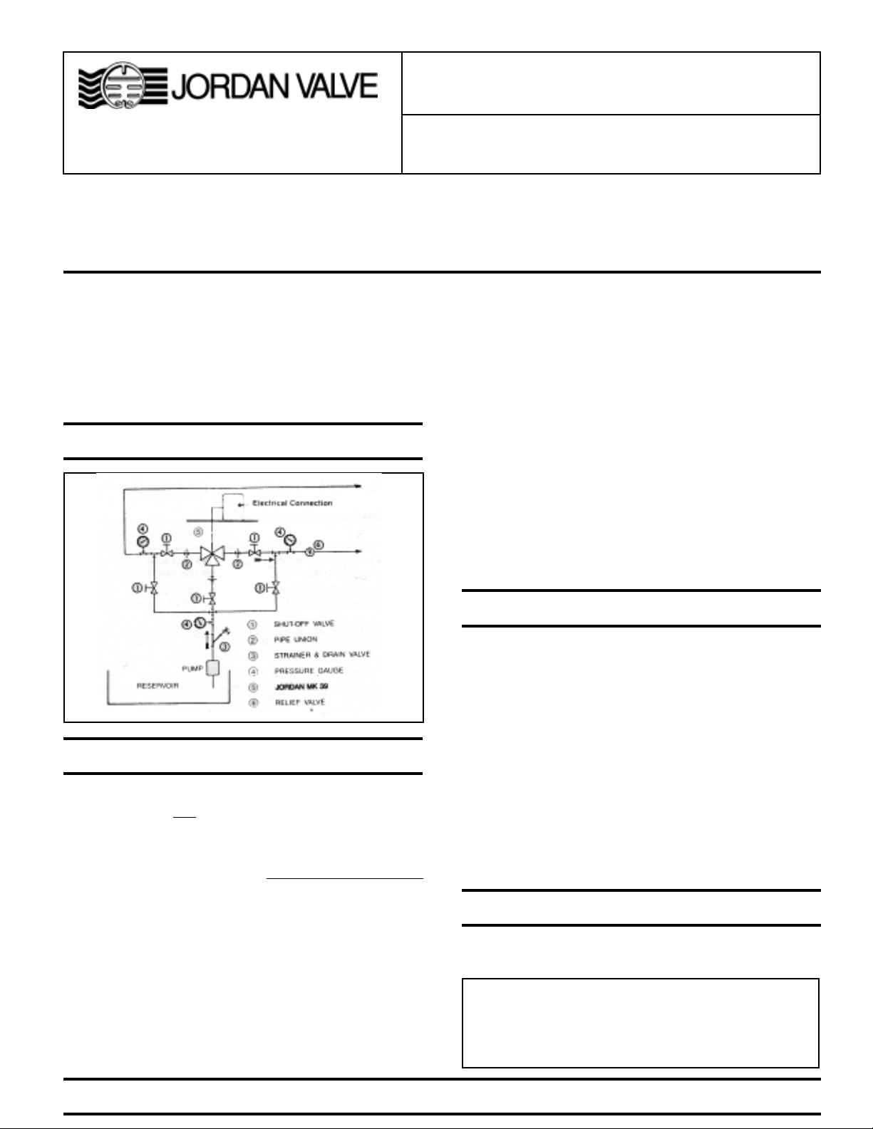
Ideal Installation Schematic
6. The flow arrow on the valve body must be pointed in the
direction of flow. Ideally, the valve should be installed in the
highest horizontal line of piping to provide drainage for
inlet and outlet piping, to prevent water hammer, and to
obtain faster response.
7. If possible, install a relief valve downstream from the valve.
Set at 15 psi above the control point of the valve.
8. In hot vapor lines, upstream and downstream piping near
the valve should be insulated to minimize condensation.
9. In gas service, if the control pressure (downstream) is 25%
of the inlet pressure or less, expand the outlet piping at
least one pipe size. A standard tapered expander connected
to the outlet of the valve is recommended.
10. Where surges are severe, a piping accumulator is recommended.
11. On steam control applications, install a steam trap with sufficient capacity to drain the coil or condenser. Be sure to
have a good fall to the trap, and no backpressure. Best
control is maintained if the coil or condenser is kept dry.
Preferred Installation
1. To protect the valve from grit, scale, thread chips and other
foreign matter,
be blown out and thoroughly cleaned before the installation process begins.
2. Shutoff valves, pressure gauges and by-pass piping should
be installed as indicated in the
to provide easier adjustment, operation, and testing.
3. A line strainer should be installed on the inlet side of the
valve to protect it from grit, scale and other foreign matter. A
.033 perforated screen is usually suitable for this purpose.
Line strainers are available from Jordan Valve.
4. For best control, 3’-0” straight sections of pipe should be
installed on either side of the valve.
5. In preparing threaded pipe connections, care should be
exercised to prevent pipe-sealing compound from getting
into the pipelines. Pipe-sealing compound should be used
sparingly, leaving the two end threads clean. Jordan uses,
and recommends, thread sealer Teflon ribbon
ALL pipelines and piping components should
Ideal Installation Schematic
Trouble Shooting
Trouble Possible Cause & Cure
Erratic Control
Will Not Operate
Oversizing causes cycling and hunting
and reduces the rangeability of the valve.
Make certain that your sizing is correct.
Steam traps downstream may need
attention.
Excessive foreign matter on seats. Clean
them.
Valve stroke out of adjustment. Check and
readjust if necessary.
Valve disc may not be moving freely.
Electrical power off or loose connection.
Defective control device.
Defective motor.
Wiring
See the motor manufacturer’s literature, supplied with the
valve, for wiring connections and instructions.
Caution: Disconnect electrical power supply before wiring
motor into circuit to avoid electrical shock or possible
damage to equipment. Always disconnect power supply
before attempting any wiring changes.
PRO TECT V ALVES WITH LINE STRAINERS
Start-Up
1. Fully open the outlet shutoff valve.
2. Slowly open the inlet shutoff valve.
3. Do not fully open the inlet shutoff valve until you are sure
that the controller and control valve have control of the
system.
Valve Maintenance
Caution: Make certain that there is no pressure in the valve
before loosening any fittings or joints. The following steps
are recommended:
1. Close the inlet shutoff valve.
2. Allow pressure to bleed off through downstream piping.
Do not attempt to reverse the valve by bleeding pressure
from the upstream side of the valve.
3. When the pressure gauges indicate that all pressure has
been removed from the system, close the outlet shutoff valve,
and the valve may be serviced.
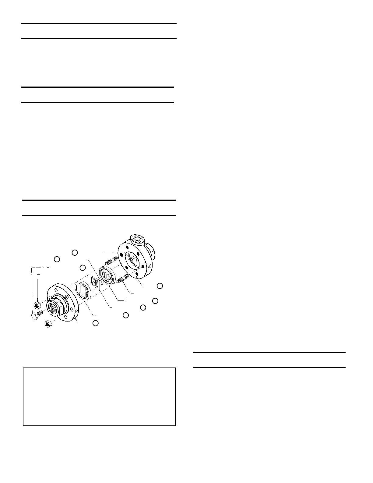
Note: refer to the drawing at the end of this document for
description and proper orientation of parts.
two nuts. Lift the cap straight up.
3. Before removing, check the disc for a stamped arrow. This
arrow points to the “<”on the body.
. (NOTE: certain discs that can be rotated 180° without
affecting the stroke might not have an arrow.)
4. Remove the disc guide (18) by lifting straight up. Also lift
straight up on the disc. Place the disc on the bench,
lapped surface facing up. Protect the lapped surfaces on
both sides of the disc guide.
5. Invert the body and lightly tap on the exterior to remove the
plate. Let the plate drop out into your hand, and place it on
the bench with the lapped surface facing up.
6. Clean all of the parts, body and cap with solvent. Place a
piece of 4/0 polishing cloth or jewelers cloth on a smooth,
flat surface, and polish the lapped seating surfaces of the
disc, plate, and disc guide using a figure “8” motion. If the
parts are scarred, do not attempt to relap them, but return
them to the factory for repair or replacement. Often parts
can be repaired at a minimal cost if the parts are not scarred
too deeply.
7. The vertical sections of the disc guide serve as guides for
the disc while stroking. A 0.005 feeler gauge should be
used to check for clearance between this surface and the
side of the disc. If the clearance is less, clean the guide
surfaces in the disc guide with a fine file.
B. REASSEMBLY
Valve Seats
14
Index Pin
Disc Pin
20
Cap
Valve Disc
Disc Guide
19
Studs (2)
Valve Plate
17
18
Body
12
16
21
Cap Screws
Hex Nuts (2)
A. DISASSEMBLY
The sliding gate seats of Jordan V alves are lapped
to light band flatness. Maintaining such tolerances
is of paramount importance for your assurance
of excellent control and tight shutoff. Do Not use
metallic objects in removing the seats. Care in
handling is imperative.
1. Follow the Maintenance Procedure and remove the valve
from line.
2. Note the scribes “<” on the side of the valve body and cap.
Secure the body flats in a vise. Remove the cap bolts and
1. Place the plate in the body, lapped surface facing the cap.
The index pin hole should be on the same side of the body
as the “<” on the body . Align the disc pin so that it is centered
in the body bore and that it protrudes through the center
slot in the valve plate (this should be the longer of the two
extensions if the disc pin is cast).
2. Place the disc on the valve plate, engaging the disc pin.
The arrow on the disc should point to the index pinhole.
Insert the index pin in the hole.
3. Place the disc guide onto the valve plate, engaging the
index pin. Rotate the assembly slightly until the slot
openings in the disc are parallel to the openings in the
plate and perpendicular to the stem. Stroking the valve will
aide in this alignment.
4. Align the “>” on the cap with the “<” on the body, and place
the cap over the two studs in the body.
5. Install the nuts and cap bolts. Tighten uniformly. See back
page for torque requirements and tightening procedures.
Repeat disassembly and reassembly per “A” and “B”
above for the second set of seats
Stem, Disc & Pin Replacement
1. Remove the disc and plate, following the procedure
outlined under VALVE SEATS.
2. Loosen the stem connector nut and bolt and remove
connector.
3. Back out the four allen head yoke screws, which will allow
the body to be separated from the yoke.
4. Remove the packing flange nuts and the packing flange.
5. Loosen the stem locknut and rotate the disc-pin counterclockwise, pulling the valve stem upward while doing so.
6. When pulling the stem completely out of the body you will
remove most of the packing assembly also. The remaining
parts of the packing assembly can “fished” out with a small
screwdriver.
 Loading...