

Page 1
I & M Mark 37 MV1005 / MV1010
3170 Wasson Road • Cincinnati, OH 45209 USA
Phone 513-533-5600 • Fax 513-871-0105
info@richardsind.com • www.jordanvalve.com
Installation & Maintenance Instructions for Mark 37
Electric Control Valve with MV1005/MV1010 Motors
Warning: Jordan Valve Electric Motor Control Valves must only be used, installed and repaired in accordance with
these Installation & Maintenance Instructions. Observe all applicable public and company codes and regulations. In
the event of leakage or other malfunction, call a qualied service person; continued operation may cause system
failure or a general hazard. Before servicing any valve, disconnect, shut off, or bypass all pressurized uid. Before
disassembling a valve, be sure to release all spring tension.
Please read these instructions carefully!
should be exercised to prevent pipe-sealing
compound from getting into the pipelines. Pipe-
Your Jordan Valve product will provide you with long,
trouble-free service if it is correctly installed and maintained. Spending a few minutes now reading these instructions can save hours of trouble and downtime later.
When making repairs, use only genuine Jordan Valve
parts, available for immediate shipment from the factory.
sealing compound should be used sparingly,
leaving the two end threads clean. Jordan uses,
and recommends, thread sealer Teon ribbon.
Install the valve in the highest horizontal line of 5.
piping to provide drainage for inlet and outlet piping, to prevent water hammer and to obtain faster
response.
The ow arrow on the regulator body must be 6.
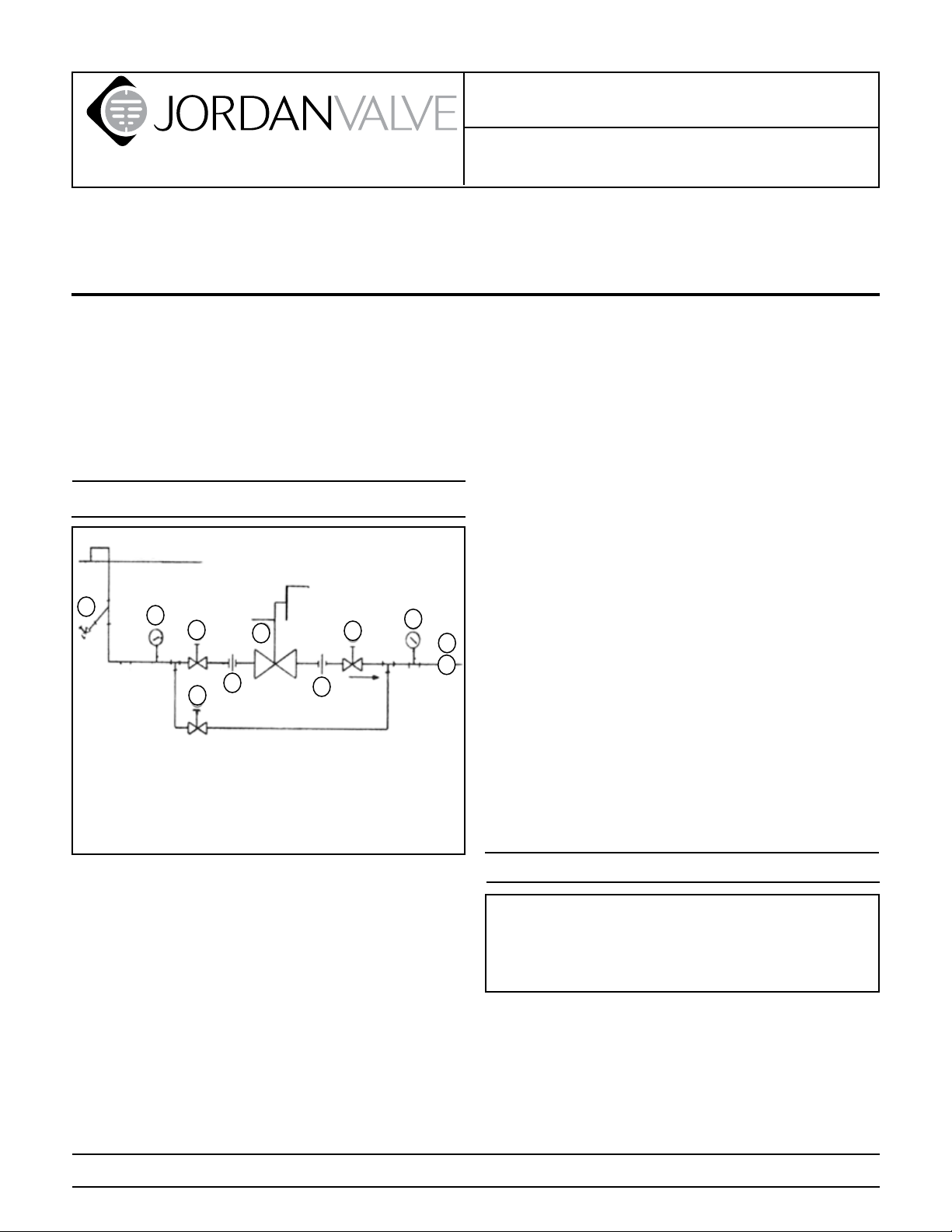
Ideal Installation
pointed in the direction of the ow. The valve may
be installed in any direction, but damage to the
Main Line
seating surfaces may occur if installed in a vertical
line with the ow upwards.
Electrical Connection
3
4
1
1
5
2
By-Pass Line
1
2
4
6
R
To minimize condensation in hot vapor lines and to 7.
protect the motor from excessive heat, piping near
the valve should be insulated.
If possible, install a relief valve downstream from 8.
the regulator. Set at 15 psi above the control point
of the valve.
Expand the outlet piping at least one pipe size if 9.
the downstream pressure is 25% of the inlet pressure or less. A standard tapered expander connect-
1. Shut off Valve
2. Pipe Union
3. Strainer and Drain Valve
4. Pressure Gauge
5. Motor Valve
6. Relief Valve
ed to the outlet of the valve is recommended.
Where surges are severe, a piping accumulator is 10.
recommended.
For best control, 3’ 0” straight sections of pipe 11.
should be installed on either side of the valve.
To protect the valve from grit, scale, thread chips 1.
and other foreign matter, ALL pipelines and piping
components should be blown out and thoroughly
cleaned before the installation process begins.
Shutoff valves, pressure gauges and by-pass piping 2.
should be installed as indicated in the Ideal Installation Schematic to provide easier adjustment, operation, and testing.
A line strainer should be installed on the inlet side 3.
of the regulator to protect it from grit, scale and
other foreign matter. A 0.033 perforated screen is
usually suitable for this purpose. Line strainers are
available from Jordan Valve.
In preparing threaded pipe connections, care 4.
PROTECT VALVES WITH LINE STRAINERS
Wiring
Caution: Disconnect electrical power supply before wiring motor into circuit to avoid electrical
shock or possible damage to equipment. Always
disconnect power supply before attempting any
wiring changes.
Make all wiring connections in accordance with local
regulations and national codes. Use No. 18 wire or larger
for all connections to the motor. No. 14 wire should be
used on runs over 500 feet long. When wiring in conduit
with other wires, motor actuator wires must have insulation equal to the other conductors in the conduit run. All
splices are to be made in junction boxes using approved
Page 2
solderless connectors or by soldering and then taping
the connections. For specic wiring instructions based
on your control range and command signal, see Supplemental Motor Literature supplied with your valve upon
shipment.
Start-Up
A. DISASSEMBLY
The sliding gate seats of Jordan Valves are
precision lapped. Maintaining such tolerances is
of paramount importance for your assurance of
excellent control and tight shutoff. DO NOT use
metallic objects in removing the seats. Care in
handling is imperative.
Be sure that the action of the control valve and of 1.
the controller are such as to give the desired results.
With the inlet, outlet, and bypass shutoff valves 2.
closed, and no pressure in the downstream line,
fully open the outlet shutoff valve. Slowly open the
inlet valve just enough to start ow through the
control valve. Increase ow gradually by slowly
opening the inlet shutoff valve. Do not fully open
the inlet valve until you are sure that the controller
and control valve have control of the system. Usually the handwheel on the inlet valve will turn freely
when this point is reached.
To shut off the line uid, close the inlet shutoff 3.
valve rst, then the outlet shutoff valve.
Maintenance
Caution: Make certain that there is no pressure in the
valve before loosening any ttings or joints. The following steps are recommended:
Close the inlet shutoff valve.1.
Allow pressure to bleed off through downstream 2.
piping. Do not attempt to reverse the valve by
bleeding pressure from the upstream side of the
valve.
When the pressure gauges indicate that all pres-3.
sure has been removed from the system, close the
outlet shutoff valve, and the valve may be serviced.
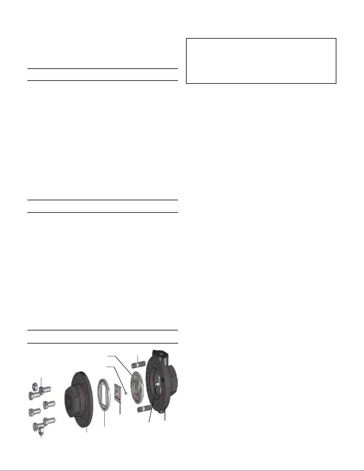
Note: refer to the drawing at the end of this document for description and proper orientation of parts.
Valve Seats
Valve Plate
Index Pin
Cap Screws
Valve Disc
Disc Guide
Cap
Hex Nuts (2)
Studs (2)
Disc Pin
Body
Close the shutoff valve on each side of the control 1.
valve, and remove the valve from the line.
Note the scribes “<” on the side of the valve body 2.
and cap. Secure the body ats in a vise. Remove
the cap bolts and two nuts, and lift the cap straight
up.
Before removing, check the valve disc for a 3.
stamped arrow. This arrow points to the “<“ on the
body. (Certain disc that can be rotated 180° without affecting valve stroke may not have an arrow.)
Remove the disc guide and the valve disc. Place
the valve disc on the bench with lapped surface
facing up. Protect the lapped surfaces on both
sides of the disc guide.
Clean all the parts, body, and cap with solvent. 4.
Place a piece of 4/0 polishing cloth or jewelers
cloth on a smooth, at surface such as surface
plate, and polish the lapped seating surfaces of the
disc, plate and disc guide using a “gure 8” motion.
If the parts are scarred, do not attempt to re-lap
them, but return them to the factory for repair or
replacement. If the seats are not scarred deeply,
they can be repaired at a nominal cost.
The vertical sections of the disc guide serve as 5.
guides for the valve disc while stroking. A 0.005
feeler gauge should be used to check for clearance
between this surface and the side of the valve disc.
If the clearance is less, clean the guide surfaces in
the disc guide with a ne le.
B. REASSEMBLY
Place the plate in the body, lapped surface facing 1.
the cap. The index pin hole should be on the same
side of the body as the “<” on the body. Align the
disc pin so that it is centered in the body bore and
that it protrudes through the center slot in the valve
plate (this should be the longer of the two extensions if the disc pin is cast).
Place the valve disc on the valve plate, engaging 2.
the disc pin. The arrow on the disc should point to
the index pinhole. Insert the index pin in the hole.
Place the disc guide onto the valve plate, engaging 3.
the index pin. Rotate the assembly slightly until the
slot openings in the disc are parallel to the openings in the plate and perpendicular to the stem.
Stroking the valve will aide in this alignment.
Align the “>” on the cap with the “<” on the body, 4.
and place the cap over the two studs in the body.
-2-
Page 3

Install the nuts and cap bolts. Tighten uniformly. 5.
See back page for torque requirements and tightening procedures.
Stem, Disc & Pin Replacement
Remove the valve disc and valve plate, following 1.
the procedure outlined under VALVE SEATS.
Remove motor following procedure outlined under 2.
MOTOR REPLACEMENT.
Loosen the lock nut and rotate the disc pin 3.
counterclockwise, pulling the valve stem upward
while doing so. Do not remove the valve stem
completely, but raise it sufciently so that the
disc pin can be removed by pulling up and out. (If
replacing stem, remove packing rst).
Reassemble the disc pin by threading it onto the 4.
stem until approximately half the thread length is
engaged in the disc pin.
Replace the motor assembly.5.
Adjust the seats per SEAT ADJUSTMENT section.6.
Packing
Remove the valve disc and plate following the pro-1.
cedure outlined under VALVE SEATS.
Remove motor following procedure outlined under 2.
MOTOR REPLACEMENT.
Remove yoke by removing the set screws. 3.
Remove both packing ange nuts.4.
Remove packing ange, packing follower, and 5.
packing.
Remove packing retainer and packing spring.6.
Clean packing bore with solvent and blow out thor-7.
oughly.
Assemble in reverse order and tighten packing nut 8.
so that the packing follower bottoms out on top of
the valve body.
Engage valve stem and actuator stem with connec-9.
tor. Stroke adjustment is required as shown in SEAT
ADJUSTMENT.
Remove the valve from the line.3.
Loosen stem connector lock nut.4.
Loosen motor lock nut.5.
Unscrew motor from yoke.6.
Remove the valve seats (see VALVE SEATS section) 7.
to prevent damage to the seats while replacing
motor.
Adjust seats per SEAT ADJUSTMENT section.8.
Seat Adjustment
Remove the seats per VALVE SEAT section and 1.
loosen the lock nut.
Rotate disc pin until it disengages from stem. 2.
For Direct Acting Valves (increase in signal closes 3.
seats): set command signal to minimum setting to
position motor at full up and limit switch tripped.
For Reverse Acting Valves (increase in signal opens
seats): set command signal to maximum setting to
position motor at full down and limit switch tripped.
Rotate disc pin onto stem until pin is at approxi-4.
mate center position in body bore.
Replace the plate in the body seat recess with the 5.
index pin hole on the same side as the scribed
line on the body and with the disc pin protruding
through the center slot in the plate.
Place the valve disc on the plate, engaging the disc 6.
pin, and with the arrow stamped on the disc pointing to the scribed line on the body.
With stem connector nuts locked again the stem 7.
connector, rotate stem connector until plate and
disc slots are in perfect alignment.
Remove the seats and tighten the lock nut. Replace 8.
the seats.
Cycle the motor to closed position and back to 9.
open position. Recheck seat alignment and make
further adjustments as required.
After seats are properly aligned, replace disc guide 10.
and cap per VALVE SEATS section. Check to make
sure all bolts are tight.
Place valve back in service.11.
Motor Replacement
Should a replacement motor be required, only a replacement motor from Jordan Valve can be used because they are factory set for the proper valve stroke.
The stroke is not eld-adjustable.
Disconnect electrical power to valve, and relieve 1.
pressure in the valve. Caution: electric power must
be disconnected before wiring motor into circuit to
avoid electrical shock or possible damage to equipment. Always disconnect power supply to motor
before attempting any wiring changes.
Remove the motor cover, mark the wires, and dis-2.
connect wires from the motor.
Trouble Shooting
If You Experience Erratic Control:
Oversizing causes cycling and hunting, and reduc-
es the rangeability of the valve. Make certain that
your sizing is correct.
Steam traps downstream may require maintenance.
Safety valve may be defective and need repair.
There may be excessive foreign matter on the
seats, and seats should be removed and cleaned.
Valve stroke may need readjustment.
Valve disc may not be moving freely. Check disc
guide clearance and correct if needed.
-3-
Page 4

If Valve Will Not Operate:
Electrical power may be off or there may be a loose
connection.
There could be a defective control device.
The motor actuator may be defective and require
replacement.
Ordering Spare Parts
Use only genuine Jordan Valve parts to keep your valve
in good working order. So that we can supply the parts,
which were designed for your valve, we must know exactly which product you are using. The only guarantee to
getting the correct replacement parts is to provide your
Jordan Representative with the valve serial number. This
number is located on the valve identication tag. If the
serial number is not available, the parts needed for your
valve might be determined using the following information: Model Number, Valve Body Size, Seat Material and
Cv Rating, Spring Range and Set Point, Trim Material, Part
Name - Number and Quantity.
NOTE: Any parts ordered without a valve serial number
that are found to be incorrect are subject to up to a minimum 25% restock charge when returned.
Torque Values (in. - lbs.)
5
3
2
1
4
6
6 bolts
(or multiples)
Valve Size
Valve Body Material
CI or BRZ DI, CS, SS
1/4” & 3/8” 70 150
1/2” - 2” 140 200
3
7
5
2
1
6
8
4
8 bolts
(or multiples)
-4-
Page 5

20
24
23
22
21
14
16
19
10
5
Illustration and Parts List
Item Description
*10 Lock Nut
*13 Packing Set
18
17
15
13
12
11
9
1 Body
2 Cap
3 Cap Bolt
*4 Plate
*5 Disc
*6 Disc Guide
*7 Index Pin (not shown)
*8 Disc Pin
*9 Stem
11 Packing Spring
12 Packing Retainer
14 Packing Follower
15 Packing Flange
16 Yoke
17 Packing Nut
18 Packing Stud
19 Set Screw
20 Motor
21 Nut
22 Stem Connector
23 Nut
24 Motor Nut
* Recommended Spare Parts
2
6
3
Bulletin IM-MK37-0909
8
4
1
3170 Wasson Road • Cincinnati, OH 45209 USA
Phone 513-533-5600 • Fax 513-871-0105
info@richardsind.com • www.jordanvalve.com
 Loading...