

Page 1
I & M Mark 25
3170 Wasson Road • Cincinnati, OH 45209 USA
Phone 513-533-5600 • Fax 513-871-0105
info@richardsind.com • www.jordanvalve.com
Warning: Jordan Valve Temperature Controllers must only be used, installed and repaired in accordance with these
Installation & Maintenance Instructions. Observe all applicable public and company codes and regulations. In the event
of leakage or other malfunction, call a qualified service person; continued operation may cause system failure or a
general hazard. Before servicing any valve, disconnect, shut off, or bypass all pressurized fluid. Before disassembling a
valve, be sure to release all spring tension.
Please read these instructions carefully!
Your Jordan Valve product will provide you with long, trouble-free service if it is correctly installed and maintained.
Spending a few minutes now reading these instructions
can save hours of trouble and downtime later. When making repairs, use only genuine Jordan Valve parts, available
for immediate shipment from the factory.
Installation & Maintenance Instructions for
Mark 25 TempilotTM Temperature Controller
ing the response time. Turning the screw counterclockwise decreases the sensitivity by increasing the flow and
reducing the response time.
Sensitivity
The sensitivity of the Tempilot controller is adjusted by
turning the restriction screw. (The restriction screw is
factory set for air operation.) For water operation, the restriction screw should be opened a minimum of 1/2 turn
and recalibrated. Restriction screw must NEVER be fully
closed. Make adjustments slowly, allowing about two minutes after each adjustment for the controller to balance.
NOTE: If sensitivity is changed, controller must be recalibrated.
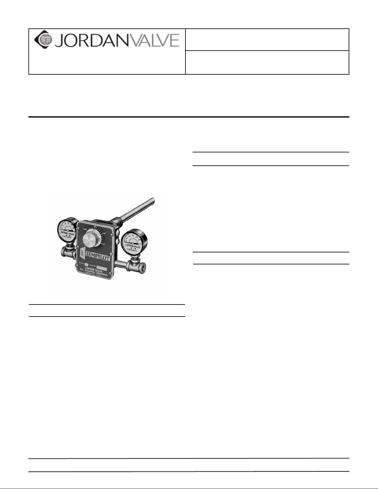
Operation
A temperature change in the medium being controlled
creates a change in length of the sensitive tube (1). An
increase in temperature lengthens the sensitive tube (1)
and moves the Invar rod (2) away from the lever (3). The
lever (4), which pivots at Point A, is moved to close the
exhaust valve (4) by spring (5). This permits the supply (air
or water) (S) to increase the pressure in the control line
(R) and close the normally open valve. A decrease in temperature shortens the sensitive tube (1) and moves the
Invar rod against the lever (3). The lever (3) moves against
the pressure spring (5), to open the exhaust valve (4). This
exhausts the pressure in the control line and opens the
valve.
The sensitivity adjustment screw (6) regulates the rate
of flow of the supply air (or water) to the controller to a
change in temperature. Turning the screw clockwise increases the sensitivity by reducing the flow and increas-
Installation
The Jordan Tempilot requires a clean, reliable supply of
compressed air or cold water at 15 - 25 pounds pressure.
Other fluids may be used, such as gas, oil, etc., providing
provision is made for safe disposal.
AIR OPERATION — The Tempilot should normally be installed in the horizontal position; however, other positions
may be used if the supply and control connections are
parallel with the ground and calibration is checked after
installation.
WATER OPERATION — The Tempilot must be installed in
the horizontal position with the drain connection at the
bottom. Drain piping should be 3/8” minimum for positive draining at all times.
1. Select the sensitive element location with care to assure satisfactory results. Bulb must project entirely
into the water or air being controlled.
2. Flush or blow out all lines before making final connections. Put supply pressure through all control
lines and check for leaks.
3. Always locate the Tempilot as close to the control
valve as possible. Piping between the Tempilot and
the control valve should be 1/8” brass pipe or 1/4”
PROTECT VALVES WITH LINE STRAINERS
Page 2
O.D. copper tubing.
4. The difference in height between the Tempilot and
the control valve should be kept to a minimum.
When the regulator is below the control valve, the
elevation cannot exceed 10’ with a 15 psi supply
pressure. If the Tempilot is above the control valve,
adjust springs on the valve to compensate for the
static head pressure.
Positions “B” and “D” (dotted)
show pivot point (B) and spring
location (D) for reverse acting
regulator.
A
B
3
C
D
2
Valve
(Normally
Open)
1
2. Install Lever (6). Tighten the Lever Pivot Screws (21)
as required. The Lever must be in the exact center
of the body and must move freely but without side
play. (For Water only — seal Lever Pivot Screws with
Loctite Grade E.)
3. Install Screws (22).
4. Install parts (8) and (9). (Note relationship for Direct
and Reverse Acting.)
5. Back up Adjustment Screw (5) until Collar (19) touches the Pivots on Lever (6).
6. Install Cover Assembly (2).
7. Install Adjustment Knob (3). The notch on Knob (3)
should be opposite the dial marking corresponding to the room temperature. Tighten the Knob Set
Screw very firmly.
8. Turn the Adjustment Knob to the desired control
temperature for an approximate calibration.
9. Recalibrate as required after the controller is installed
and connected to the supply and control lines.
5
6
R
4
S
Figure 1
Calibration
1. To calibrate the Tempilot, turn the adjusting knob
until a 7-1/2” psi control pressure shows on the
gauge.
2. Read the temperature at the bulb with an accurate
thermometer.
3. Loosen the set screw in the adjusting knob and turn
the adjusting knob to indicate the temperature at
the bulb.
4. Tighten the set screw.
5. Now set the Tempilot for the desired temperature for
your process.
Both Air and Water Controller
A. Disassembly (Refer to Figure 4 on page 3)
1. Remove Knob (3) after loosening its Set Screw.
2. Remove Cover Assembly (2).
3. Remove Lever Spring Retainer (8) and Lever Spring
(9).
4. Back up one Lever Pivot (21) and remove Lever (6).
5. Unscrew Sensitive Tube Assembly (20) from Body
(1).
Lever Spring
Retainer
Direct Acting spring
in front of lever. For
Figure 2
Reverse Acting, place
spring behind lever.
Please note Figure 2. This figure shows how the lever
spring and the lever spring retainer should be assembled
in front of the lever for direct acting regulators. Also note
that the lever pivots and the lever pivot set screws are assembled in the top two pivots for a direct acting Tempilot
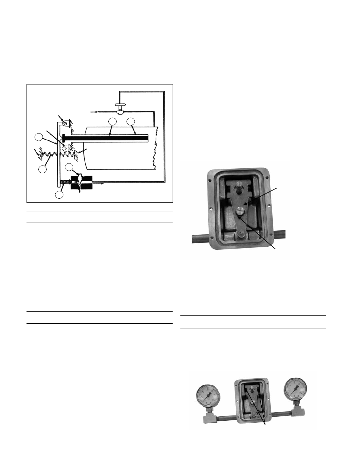
Reversing Tempilot Action
Please note Figure 3. Since this is a reverse acting Tempilot, the lever spring retainer is in front of the lever, and
the lever spring is behind the lever. Also, the lever pivots
and the lever pivot set screws are in the lower two pivot
points.
Figure 3
B. Assembly
1. Install new Sensitive Tube Assembly (20) to body
(1).
Set Screws (Reverse Acting)
-2-
Page 3

Air Service Only:
1. Turn the Adjusting knob clockwise to remove tension.
2. Remove the adjusting knob set screw and remove
the adjusting knob (3).
3. Remove the cover screws (10) and the cover (2).
4. Remove the lever spring retainer (8) and lever spring
(9).
5. Relocate the lever pivot (21) to change the pivot
point.
6. Turn lever pivots in to be snug without binding.
7. Replace the lever spring retainer and lever spring to
obtain the desired action.
8. Replace the cover and the adjusting knob.
9. Recalibrate.
Figure 4
Direct Acting Pivot
AA
22
Reverse
Acting
Pivot
1/8” NPT Return
1/4” NPT Return
Ordering Spare Parts
Use only genuine Jordan Valve parts to keep your valve
in good working order. So we can supply the parts, which
were designed for your valve, we must know exactly which
product you are using. The only guarantee to getting the
correct replacement parts is to provide your Jordan Representative with the valve serial number. This number is
located on the valve identification tag. If the serial number
is not available, the parts needed for your valve might be
determined using the following information: Model number, Valve Body size, Plug Material and Seat Size, Spring
Range or Set Point, Trim Material, Part Name - Number
and Quantity (see parts list chart).
1/8” NPT Return
21
Section “A-A”
Air Operated
Note: Without a valve serial number, any parts ordered
incorrectly are subject to a minimum 25% restock charge
when returned.
-3-
Page 4

Illustration and Parts List
10
1
2
5
7
3
4
6
8
9
11
2-1/4”
13 15 16
12
1-19/32”
19
18
17
20
8
9
Reverse Acting
Spring Location
Water Operated
11-15/16”
30
18
17
Item Description Qty. Item Description Qty.
1 Body 1 13* Valve 1
2 Cover Plate 1 15 Valve Spring 1
3 Adjusting Knob 1 16* Valve Seat 1
4 Quad Ring 1 17 Restriction Screw 1
6 Lever 1 18* O-Ring 1
7 Set Screw 1 19 Thrust Collar 1
8 Spring Retainer Screw 1 20 Sensitive Tube Assembly 1
9 Lever Spring 1 21 Lever Pivot 2
10 Cover Screw 6 30* Insert 1
11 O-Ring 1 31 Sealing Screw 4
12* Retaining Ring 1 32* Gasket 4
* Recommended Spare Parts
Note: Accessory parts included with controller:
Pipe Nipple, QTY 2
1/8” Brass Tee, QTY 2
0-30 psi Gauge, QTY 2
Optional thermowell available is SST or Copper
Bulletin IM-MK25-1111
3170 Wasson Road • Cincinnati, OH 45209 USA
Phone 513-533-5600 • Fax 513-871-0105
info@richardsind.com • www.jordanvalve.com
 Loading...