

Page 1
I & M Mark 17X Series
3170 Wasson Road • Cincinnati, OH 45209
Phone 513.533.5600 • Fax 513.871.0105 (f)
info@richardsind.com • www.jordanvalve.com
Warning: Jordan Valve Control Valves must only be used, installed and repaired in accordance with these Installation & Maintenance Instructions. Observe all applicable public and company codes and regulations. In the event
of leakage or other malfunction, call a qualified service person; continued operation may cause system failure or
a general hazard. Before servicing any valve, disconnect, shut off, or bypass all pressurized fluid. Before disassembling a valve, be sure to release all spring tension.
InstallatIon- lInear
Note: Prior to installing positioner, ensure all safety
precautions have been taken.
- All input or supply pressure to valve,
actuator and or other related devices must
be shut off
- Use proper lock out procedures
- A bypass valve or other supportive equip ment may be used to avoid entire system
“shut down”
- Ensure any remaining actuator pressure
has been fully relieved
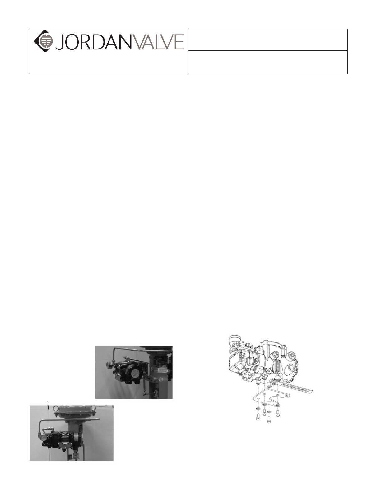
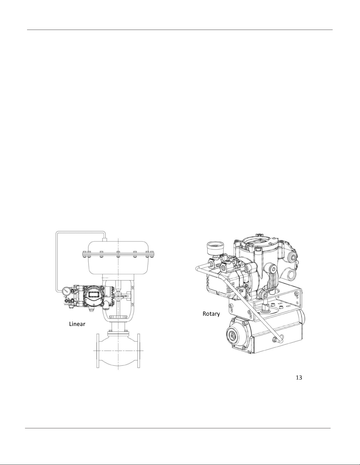
Mark 17X Linear Installation
The Mark 17X Linear Smart Positioner should be installed on linear motion valves such as a globe or gate
style valve which uses linear motion spring type or
piston actuators. Prior to installation, have the following
items available:
- Mark 17X Positioner
- Feedback Lever and Lever Spring
- Flange Nut (bottom side of 3400L)
- Qty. 4, Hex Head Bolts (M8x1.25P)
- Qty. 4, M8 Flat Washers
- Mounting Kit
- Bracket
Installation & Maintenance Instructions for the
Mark 17X Series Smart Positioner
*A proper mounting bracket must be used in order
to adapt the Mark 17X positioner to the actuator yoke. Contact a Jordan Valve representative
should a bracket be required for a Jordan Valve
Actuator.
If having a bracket made to best suit the application, consider the following:
- The positioner feedback lever must be
parallel to the ground at 50% of the valve
stroke.
- The feedback lever connection with the
pin of the actuator clamp should
be installed in such a way that the valve
stroke length coincides with the corre-
sponding figure in “mm” marked on the
feedback lever. Improper setting may
cause poor linearity, and may create
unnecessary hunting during the
operation.
1. Assemble the mounting bracket to the
backside of the positioner using 4, M8 X
1.25 bolts and lock washers.
Page 2
Mark 17X SerieS FlaMeprooF SMart poSitionerS
Linear Installation, Continued
2. Attach the positioner and mounting bracket to
the actuator yoke – DO NOT FULLY TIGHTEN
FASTENERS COMPLETELY
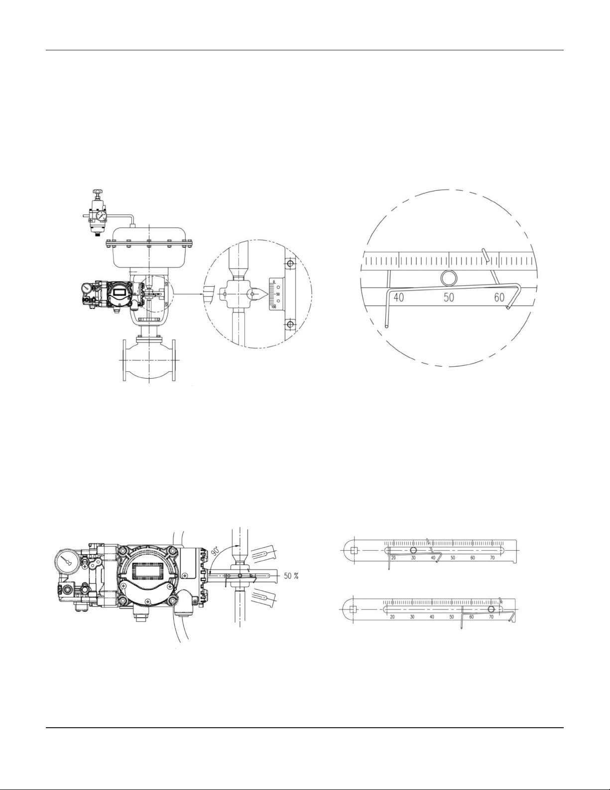
3. Connect the positioner feedback lever to the
actuator clamp. The gap on the feedback lever
is 6.5mm. The connection pins
outer diameter should be less than 6.3 mm.
4. Temporarily connect supply pressure to the
actuator. Supply enough pressure to to the
actuator in order to position the actuator clamp
at 50% of the total valve stroke.
5. Insert a connection pin into the feedback lever.
The pin should be inserted when the actuator
clamp is at 50% of the total valve stroke.
Feedback lever, connection pin, and spring connections detail
6. Ensure feedback lever is parallel to the ground
at 50% of the valve stroke. Make adjustments to
the bracket or feedback link bar as required.
Improper installation may cause poor
linearity and may create unnecessary hunting
during the operation.
7. Check the valve stroke. The stroke marks are
indicated on the feedback lever of the
Mark 17X positioner. Position the
connection pin at the number on the feedback
lever which corresponds to the desired valve
stroke. Adjustments may be made by moving
the bracket, the connection pin, or both.
Pin insertion when valve stroke is
30mm (up) and 70mm (bottom)
-2-
Page 3
Mark 17X SerieS FlaMeprooF SMart poSitionerS
Linear Installation, Continued
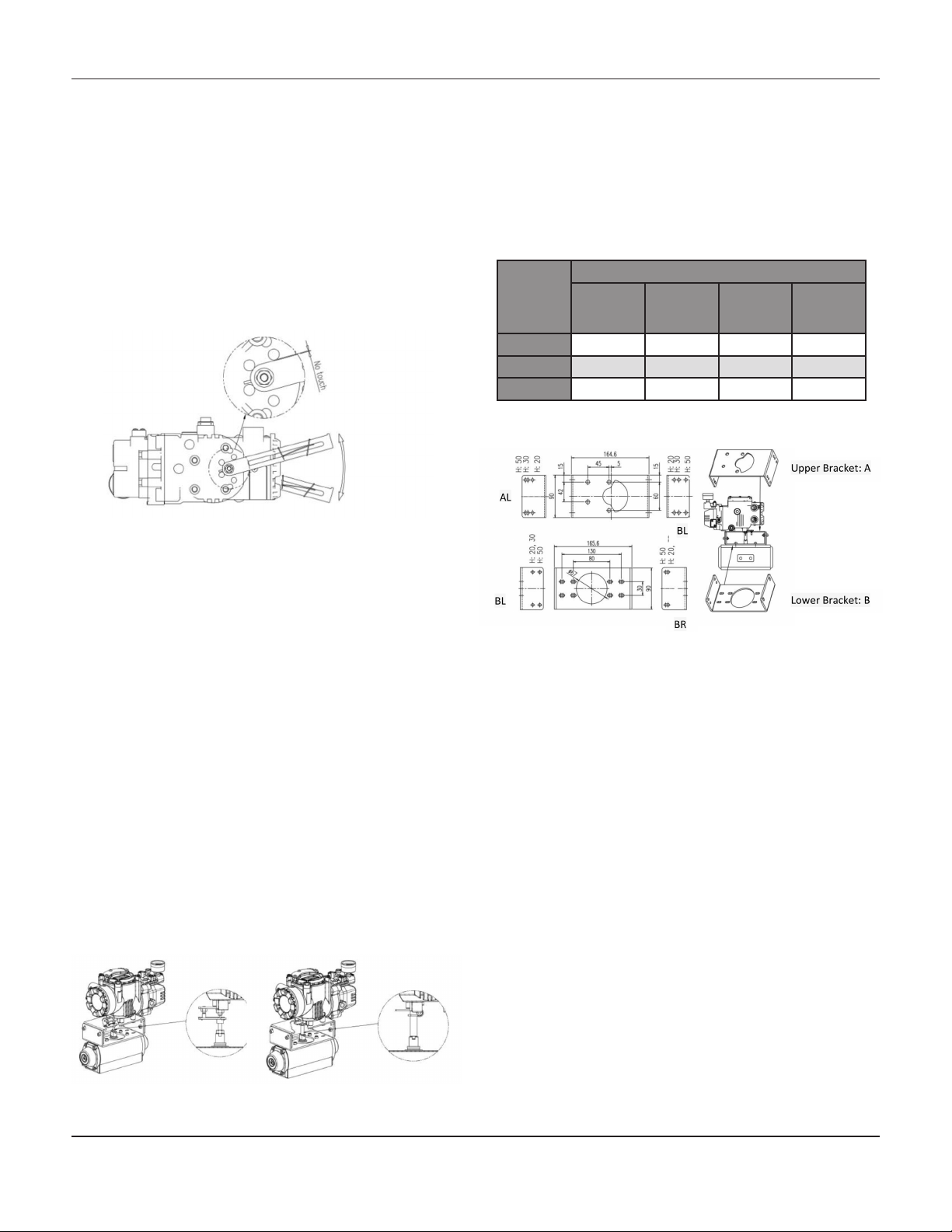
8. After installing the positioner, operate the
valve from 0% to 100% stroke by using direct
air to the actuator (manual position). At both
0% and 100% the feedback lever should not
touch the lever stopper, which is located on the
back of the positioner. Should the feedback
lever touch the stopper, adjustments may be
required to install the positioner further away
from the actuator yoke.
Bracket Information:
The supplied standard bracket contains two components. The bracket may be used for both fork
lever type and NAMUR lever type configurations.
The bracket is designed to fit on the actuator with a
20mm stem height (H). Should the stem height be
30mm or 50mm, the bracket must be adjusted as
required.
Actuator
Stem
Height
(H)
20 mm H: 20 H: 20, 30 H: 20 H: 20, 30
30 mm H: 30 H: 20, 30 H: 30 H: 20, 30
50 mm H: 50 H: 50 H:50 H: 50
A-L B-L A-R B-R
Bolt Hole Markings
9. After installation and adjustment have been
made, complete by tightening the bolts on the
bracket, feedback lever, and the
connection pin.
InstallatIon- rotary
Mark 17X Rotary Installation
The Mark 17X Rotary Smart Positioner should be installed on rotary motion valves, such as ball or butterfly
type valves which use a rack and pinion, scotch yoke,
or other type of actuator which uses 90 degree rotation.
Prior to installation have the following items available:
- Mark 17X Positioner
- Fork Lever and Lever Spring
- Standard rotary bracket (supplied)
- Qty. 4, Hex Head Bolts (M8x1.25P)
- Qty. 4, M8 Flat Washers
1. Check actuator stem height and adjust as
required.
2. Attach the bracket to the actuator. Use lock
washers to prevent the bolts from loosening from
vibrations.
3. Set the rotation position of the actuator stem to
0%. For single acting actuators, with
no supply pressure to the actuator, the stem will
be at 0%. For double acting actuators,
check the actuator stem rotation
direction – clockwise or counter clockwise- by
supplying pressure to the actuator.
-3-
Page 4
Mark 17X SerieS FlaMeprooF SMart poSitionerS
Rotary Installation, Continued
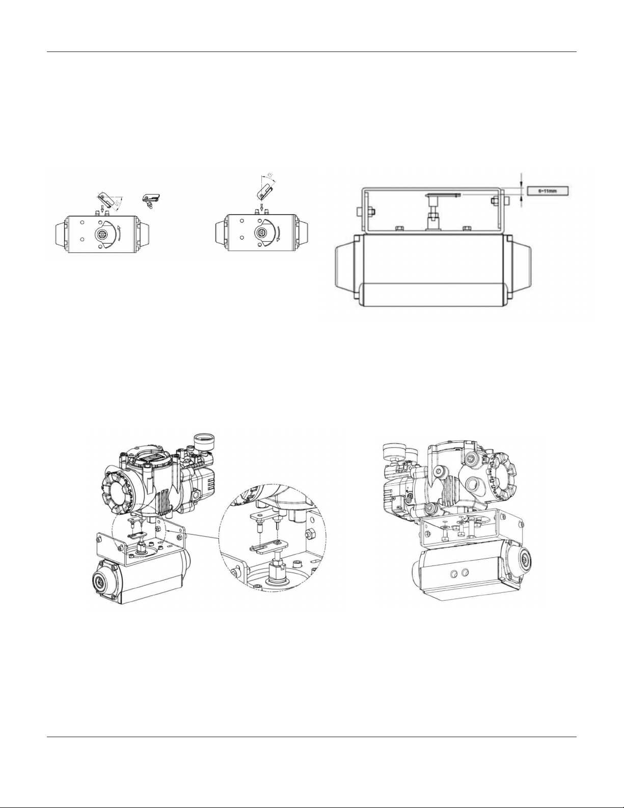
4. Install the fork lever after setting the actuators
stem at 0%. Check the actuator stem rotation
direction, clockwise or counter clock
wise. Install the fork lever at 45 degrees in
relation to the linear shaft. For NAMUR mount
installation, this angle does not apply.
Counter Clockwise and Clockwise rotation
6. Attach the positioner to the bracket. Fix the clamping pin on the main shafts center of the positioner, and
insert the connection pin into the fork lever slot. This will lock the fork lever spring. Ensure proper alignment
of the positioners main shaft centered to the actuator stem. Poor alignment may decrease the positioners
durability due to unnecessary forces on the main shaft.
5. After setting the fork lever position, assemble
the lock nuts which are located on the bottom
of the fork lever. Ensure the set height of the
upper fork lever is between 6mm to 11mm from
the top of the mounting bracket.
-4-
Page 5
Mark 17X SerieS FlaMeprooF SMart poSitionerS
Rotary Installation, Continued
7. Tighten the positioner and the bracket using the hex head bolts and plate washers, after checking for
proper alignment and position of the Mark 17X positioner.
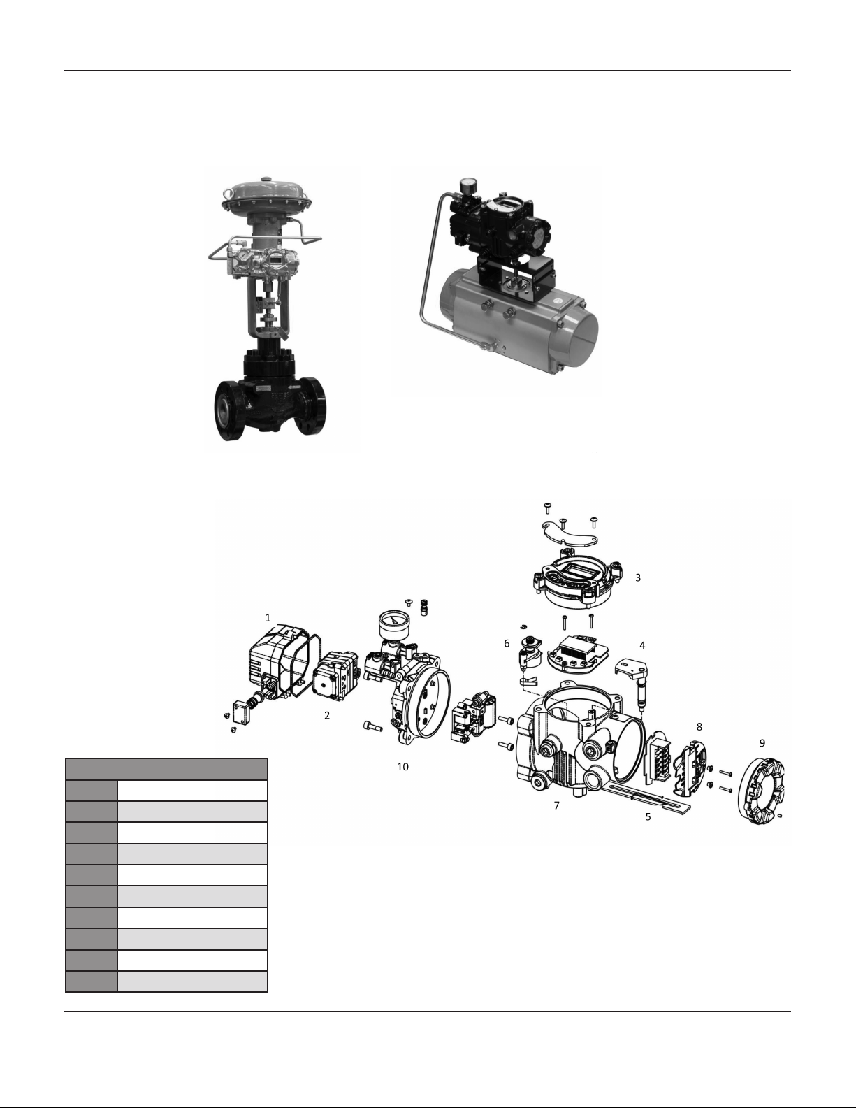
Mark 17X asseMbly
Mark 17X Assembly
1 Pilot Cover
2 Pilot Unit
3 Main Cover
4 Main PCB
5 Feedback Lever
6 Potentiometer
7 Main Body
8 Terminal PCB
9 Terminal Cover
10 Manifold
-5-
Page 6
Mark 17X SerieS FlaMeprooF SMart poSitionerS
ConneCtIons
Supply:
Supply pressure should be clean, dry air. Avoid moisture, oil and dust. It is recommended that a filter regulator be
used as part of a complete installation to ensure proper operation and durability.
Supply Pressure Conditions:
- Dry air of at least 10oC lower than ambient temperature.
- The Mark 17X internal filter is capable of 5 micron or larger, always use a filer regulator to ensure clean air
is being supplied to the positioner.
- Avoid oil.
- Supply pressure range is 20psig – 100psig.
- Set air filter regulator pressure level 10% higher than actuators spring range pressure.
- Comply with ANSI/ISA-57.3 1975(R1981) or ISA S7.3-1975(R1981)
Piping Conditions:
- Ensure all piping is clean and free of obstructions.
- Do not use piping that is squeezed or restricted, or shows any type of damage.
- Minimum piping inside diameter should be at least 6mm (.25”) to maintain proper flow rate.
- Avoid excessively long runs of piping. Flow rates may be affected due to friction inside the piping.
Connection: Single Acting Actuator,
Single acting type positioner is set to the OUT1 port. Supply pressure port rom the actuator should be connected to
the OUT1 port when using single acting type, spring return actuation.
-6-
Page 7
Mark 17X SerieS FlaMeprooF SMart poSitionerS
ConneCtIons, ContInued
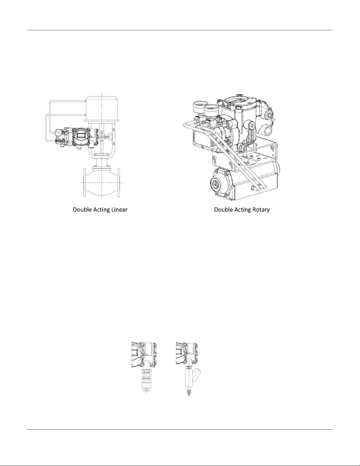
Connection: Double Acting Actuator,
Double acting type positioner is set to use the OUT1 and OUT2 ports. As the input signal increases the supply pressure will be supplied through the OUT1 port.
Power Connections:
Ensure safety codes applicable to the location are adhered to as required.
- When installing in hazardous locations, proper conduit tubing or pressure proof packing union must be
used. The compound charging box should be flameproof type and completely sealed.
- Standard conduit entry tap is PF (G) 1/2"
- Before connection the terminal, ensure proper safety precautions have been taken, and all power is com
pletely shut off. Do not open the cover while power to the positioner is live.
- Positioners with PTM option must be supplied with 10~28V DC separately. For L/S option, separate 12-24V
DC must be supplied. Do not exceed 30V DC if both options are being utilized.
- Ensure proper grounding of the positioner.
- Ensure proper wiring is utilized in accordance to local codes and installation application. It is recommended
that shielded wiring be used to protect from electro-magnetic field and noise. Do not install the cable near
high noise environments, such as high capacity transformer or motor.
-7-
Page 8
Mark 17X SerieS FlaMeprooF SMart poSitionerS
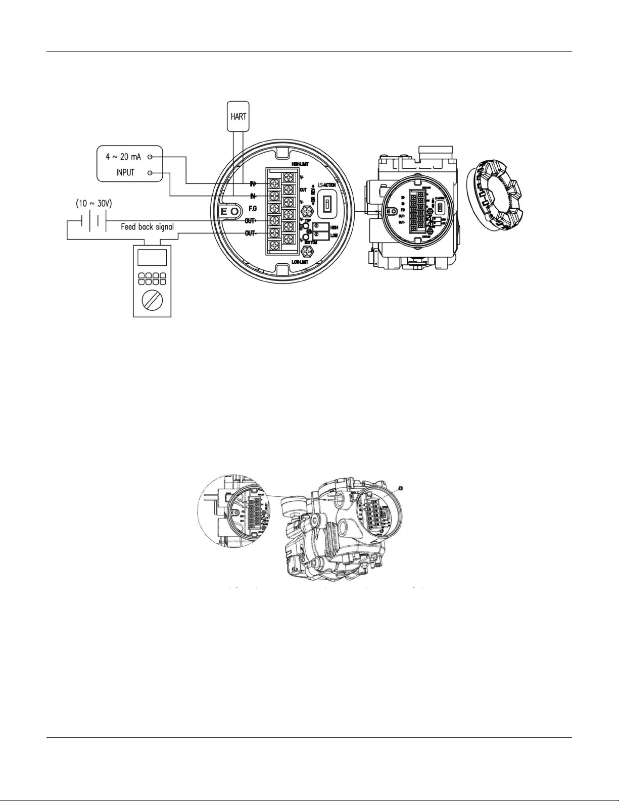
terMInal overvIew and ConneCtIons
Positioner Terminal:
IN + : Input Signal (positive)
IN - : Input Signal (negative)
OUT + : Feedback Signal (positive)
OUT - : Feedback Signal (negative)
Input Signal Terminal:
1. Open terminal cover by removing set screw using a 3mm hex key
2. There are two conduit entries on the bottom side of the positioner to allow for cable entry best suited to the
application.
3. Locate the correct terminal for the input signal on the bottom of the positioner. Insert the terminal wiring
through the conduit entry and properly secure them to the IN+ (positive) and IN– (negative) terminals on the
plate. Tighten fasteners to 1.5Nm (13 in lbs).
4. Close the terminal cover, and tighten the set screw stopper.
Top Right 3 Terminals : Limit Switch 0%
Bottom Right 3 Terminals : Limit Switch 100%
-8-
Page 9
Mark 17X SerieS FlaMeprooF SMart poSitionerS
terMInal overvIew and ConneCtIons, ContInued
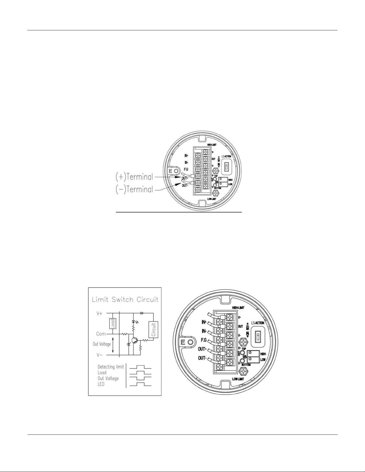
Feedback Signal Terminal:
1. Open terminal cover by removing set screw using a 3mm hex key
2. There are two conduit entries on the bottom side of the positioner to allow for cable entry best suited to the
application.
3. Locate the correct terminal for the input signal on the bottom of the positioner. Insert the terminal wiring
through the conduit entry and properly secure them to the OUT+ (positive) and OUT– (negative) terminals
on the plate. Tighten fasteners to 1.5Nm (13 in lbs).
4. Close the terminal cover, and tighten the set screw stopper.
Limit Switch Terminals:
1. With the cover off, locate the limit switch terminals.
2. Connect to the proper terminals accordingly, paying attention to both correct polarity as well as top three
right for Limit Switch 0% , and bottom three right for Limit Switch 100%.
3. Make connections and fasten terminal screws to 1.5 Nm (13 in lbs)
4. Close terminal cover and tighten the set screw stopper.
-9-
Page 10

Mark 17X SerieS FlaMeprooF SMart poSitionerS
terMInal overvIew and ConneCtIons, ContInued
Ground:
1. Prior to operating the positioner, please ensure that it has been properly grounded.
2. Open terminal cover and locate the ground terminal. Resistance should be less than 100ohm.
3. When using the external ground, use a Phillips head screwdriver to remove the ground screw. Insert the
outside ground bolts and spring washer into the ring type terminal of the ground cable and tighten
accordingly.
4. When using the internal ground, remove the terminal cover, locate the grounding screw marked E, and make
connections as required.
-10-
Page 11

Mark 17X SerieS FlaMeprooF SMart poSitionerS
adjustMents
Limit Switch Adjustments
1. HIGH variable resistor adjusts the sensing point of the valve end point. For Direct Acting, it will sense 4mA
point, and for Reverse Acting, 20mA of the input signal will be the sensing point. Red LED will be lit upon
sensing.
2. LOW variable resistor adjusts the sensing point of the valves zero point. For Direct Acting, it will send 20mA
point, and for Reverse Acting, 4mA of the input signal will be the sensing point. Red LED will be lit upon
sensing.
3. If V+ and COM terminals are connected, electric current may be used on limit switch for an alarm or light
indicator as required.
4. If V- and COM terminals are connected, electric voltage may be used on limit switch to receive a signal from
a computer.
5. LS-ACTION, switch to change between Direct (DR), Reverse (REV) action.
6. By adjusting the variable resistor, the limit switch operating range may be set. Turn Clockwise to widen
the range, and Counter Clockwise to shorten the range. As the range adjusts, the red LED will light
to indicate the completion of adjustments.
Variable Orice Adjustments
Hunting may occur when the actuator volume is too small. In order to prevent hunting, orifice adjustments may be
made. By adjusting the orifice, the flow rate of the supply pressure may be adjusted. Use a flathead screwdriver to
make adjustments as required.
-11-
Page 12

Mark 17X SerieS FlaMeprooF SMart poSitionerS
operatIon
The following process will operate the valve and actuator. Prior to proceeding with any AUTO Calibration
please isolate the valve and actuator from the system.
Button Description:
Behind the access panel on the front of the positioner, there are 4 buttons. Simply back off the three Phillips head
screws slightly and rotate the cover upwards to gain access.
Run Mode (RUN):
Once power is turned on to the positioner, RUN mode will be displayed within 6 seconds on the LCD screen. RUN
indicated the positioner will adjust the valve stoke according to the input signal. There are 6 modes within RUN
cycle.
1. RUN PV : Process Value – valve stroke %
2. RUN SV % : Set Value – input signal 0-100%
3. RUN SV mA : Set Value – input signal 4~20mA
4. RUN MV : Manipulate Valve – Motor Manipulate Value (digit)
5. RUN Vel : Velocity – Current valve stem velocity (digit)
6. RUN Err : Error – Difference between SV and PV (%)
To cycle display modes, press “ESC” and “+” at the same time. This will cycle display modes in the order indicated
above. Alternatively pressing “ESC” and “-“ will cycle through the above modes in descending order.
Pressing “ESC” at any point will return the Mark 3400 positioner to RUN mode.
-12-
Page 13

Mark 17X SerieS FlaMeprooF SMart poSitionerS
operatIon, ContInued
Auto Calibration:
The Auto Calibration mode (AUTO CAL) will automatically calibrate the positioner. The AUTO CAL process will take
2-3 minutes, depending on the application.
There are three modes of AUTO CAL:
*It is recommended that AUTO2 calibration be performed for initial settings.
Mode Zero Point End Point KP, KI, KD RA, DA
AUTO 1 Yes Yes No No
AUTO 2 Yes Yes Yes Yes
AUTO 3 No No Yes Yes
AUTO1 Calibration Mode:
AUTO1 mode will change zero, and end points. However KP, KI, and KD will not be adjusted. Should the field
user wish to re-calibrate the positioner from the initial settings from the valve manufacturer, it is recommended that
AUTO1 be used.
AUTO2 Calibration Mode:
AUTO2 mode will calibrate all parameters. It is recommended to use AUTO2 mode after initial installation of the
Mark 17X positioner.
-13-
Page 14

Mark 17X SerieS FlaMeprooF SMart poSitionerS
operatIon, ContInued
AUTO3 Calibration Mode:
AUTO3 will only change the valve parameters. Zero and End Point adjustments will not be made.
Manual Mode:
MANUAL mode is used to adjust the valves stems movement manually. In MANUAL mode the positioner will bypass
the supply pressure to the actuator. The valve stems movement in this mode will not affect the positioners save data
values.
PARAM – Parameter Mode:
While AUTOCAL optimizes the actuator values, in some applications where hunting or oscillation occurs it may be
necessary to make additional adjustments in PARAM mode.
Once the parameter values have been adjusted, the new values are saved as soon as they are adjusted. There
is no need to return to RUN mode after changes are made to observe the changes.
-14-
Page 15

Mark 17X SerieS FlaMeprooF SMart poSitionerS
operatIon, ContInued
dEAdZONE – Deadzone mode:
dEAdZONE mode indicates the percentage of error allowance. In cases of high level packing friction, which may
cause hunting, creating Deadzone can stable the valves operation.
P1 Value – (KP1):
P Value indicates the ratio of the compensation signal, based on the percentage of error allowance. As the value
increases, the positioner will find the target value quickly, however it is more likely to create a hunting effect.
-15-
Page 16

Mark 17X SerieS FlaMeprooF SMart poSitionerS
operatIon, ContInued
D1 Value – (Kd1):
D Value indicates the derivative value of the compensation signal, based on the percentage of error allowance. As
the value increases, it is more likely to create a hunting effect. As the value decreases, it may create poor linearity.
P2 (KP2) and D2 (Kd2) Values:
P2 and D2 value principles are the same as P1 and D1, however, these values are only applicable when the input
signal is decreasing.
P_ (KP_) and D_ (Kd_) Values:
P_ and D_ value principles are the same as P and D, however these values are only applicable when the positioners
actual stroke reaches the target stroke per input signal.
PT1 and PT2 Values:
PT value indicates the minimum time duration of internal signal. PT1 is for an increased input signal, and PT2 is for
decreased input signal PT Values.
-16-
Page 17

Mark 17X SerieS FlaMeprooF SMart poSitionerS
operatIon, ContInued
Period T:
Period T indicates the positioners internal control time interval. By default the Mark 17X will check the current position, respective to the current input signal every 100 msec.
Auto DZ (AUTO dZ):
After auto calibration, the positioner will automatically create deadzone. In some cases due to valve packing friction,
it may be necessary to increase the deadzone settings to reduce hunting or oscillation.
-17-
Page 18

Mark 17X SerieS FlaMeprooF SMart poSitionerS
operatIon, ContInued
*Hand Calibration Mode (HAND CAL):
The Mark 17X may be manually calibrated by selecting the Hand Calibration Mode.
Zero Point (PV_ZERO) and End Point (PV_END) Values:
PV_ZERO adjusts the Zero Point of the valve, while PV_END will adjust the end point of the valve.
-18-
Page 19

Mark 17X SerieS FlaMeprooF SMart poSitionerS
operatIon, ContInued
Zero Point (TR_ZERO) and End Point (TR_END) for transmitter:
TR_ZERO will adjust the zero point of the
transmitter (4-20mA feedback), and
TR_END will adjust the end point of the
transmitter (4-20mA feedback).
End Point Ratio for Valve (PE_TRIM):
When reverse acting operation is used, the End Point may be adjusted within 10% of the total valve stroke, without
adjusting the valves zero point.
-19-
Page 20

Mark 17X SerieS FlaMeprooF SMart poSitionerS
operatIon, ContInued
Normal / Reverse Feedback Signal (TR_NORM/REV):
The feedback signal from the positioner may be set as normal or reverse.
Normal/Reverse HART Signal (HT_NORM/REVS):
HART signal from the positioner can be set as normal or reverse.
-20-
Page 21

Mark 17X SerieS FlaMeprooF SMart poSitionerS
operatIon, ContInued
*Valve Mode (VALVE)
Acting Adjustments (ACT):
The positioner may be set as Direct Acting (DA), or Reverse Acting (RA).
Characteristic Adjustments (CHAR):
The valve characteristics may be set on the field requirements. There are 3 selectable valve characteristics – Linear
(LIN), Equal Percentage (EQ), and Quick Opening (QO).
-21-
Page 22

Mark 17X SerieS FlaMeprooF SMart poSitionerS
operatIon, ContInued
User Characteristics (USER SET):
Should the positioner require a specific characteristic, the valve characteristic curve can be made by selecting up to
16 points of the curve.
Tight Shut Open (TSHUT OP):
Tight Shut Open allows the valve to open completely as the input signal reaches 20mA.
-22-
Page 23

Mark 17X SerieS FlaMeprooF SMart poSitionerS
operatIon, ContInued
Tight Shut Close (TSHUT CL):
Tight Shut Close allows the valve to close completely as the input signal reaches 4mA.
Split Range Mode (SPLIT):
The valve may be operated by split range control, 4-12mA or 12-20mA.
Custom Zero Setting Mode (CST ZERO):
Allows the user to set any specific point as a zero position. For example, the zero point may be set at an input signal
of 7mA.
-23-
Page 24

Mark 17X SerieS FlaMeprooF SMart poSitionerS
operatIon, ContInued
Custom End Setting Mode (CST ENd):
The Custom End Setting Mode allows the user to set any specific point as the end position. For example, the end
point may be set at 11mA.
*The difference, between the zero and end points must be greater or equal to 4mA.
Interpolation Mode (ITP OFF/ON):
The positioner can accurately control the valve if the feedback lever angle range is within the designed range. In
some instances, if the angle exceeds the suggested range angle, Interpolation Mode can reduce the error.
-24-
Page 25

Mark 17X SerieS FlaMeprooF SMart poSitionerS
operatIon, ContInued
View Mode (VIEW):
View Mode displays positioner information on the LCD.
Display Description
2600L Positioner Model
VERSION Main Software Version
HART V HART Protocol Version
POL AddR HART Protocol Channel Address
0Y 0d Total usage time duration
FULL_OP Time elapsed for valve to fully open
FULL_CL Time elapsed for valve to fully close
VM NOR Type of valve stroke (in percentage or value)
Erro Error code warning message
ABS Absolute Resistance Value
-25-
Page 26

Mark 17X SerieS FlaMeprooF SMart poSitionerS
error and warnIng Codes
Error code Code Description and Cause Action
MT ERR L - Positioner is improperly installed
- Positioner is not level to the ground at 50% point.
Lever is at lower position than actual 50% point
MT ERR H - Positioner improperly installed
- Positioner is not level to the ground at 50% point.
Lever is at higher position than actual 50% point
CHK AIR Valve does not operate when the positioner receives
“Full Open” signal during Auto Cal
RNG ERR Operating angle is too small due to improper
positioner installation
Error of 10% or more persists for more than 1 minute
C
D
B - Pv Span – Pv Zero range is below 500
F
G - Pv is below 100
H - Pv is over 4000
- No valve movement
- High level of valve friction
- Changes in setting pressure of actuator
I value reaches a maximum or minimum limit
- Changes in valve friction
- Changes in setting pressure of actuator
- The angle of the feedback lever is too small
- Full Open/Close elapsed time is less than one
second
- Actuator size is too small
- The angle of the feedback lever is too large
- The angle if the feedback is too large
- Reinstall the positioner
- Ensure the feedback lever does not
touch the stopper at 0% and 100%
- Reinstall the positioner
- Ensure the feedback lever does not
touch the stopper at 0% and 100%
- Check supply pressure levels
Adjust the mounting bracket so the
positioner can be mounted closer to
the actuator
- Perform BIAS calibration
- Check setting pressure of actuator
- Perform Auto Cal
- Check setting pressure of actuator
- Reinstall the positioner
- Ensure the feedback lever does not
touch the stopper at 0% and 100%
- After reinstallation perform AUTO1
- Use variable orifice
- Use larger actuator
- Reinstall the positioner
- Ensure the feedback lever does not
touch the stopper at 0% and 100%
- After reinstallation perform AUTO1
- Reinstall the positioner
- Ensure the feedback lever does not
touch the stopper at 0% and 100%
- After reinstallation perform AUTO1
-25-
Page 27

MaIn software Map
MK17XIM/0214/2K
Mark 17X SerieS FlaMeprooF SMart poSitionerS
Jordan Valve, a division of Richards Industries
3170 Wasson Road • Cincinnati, OH 45209
513.533.5600 • 800.543.7311 • 513.871.0105 (f)
info@richardsind.com • www.jordanvalve.com
 Loading...