

Page 1
Richards Industries
Basic Siemens PS2 Positioner Functions
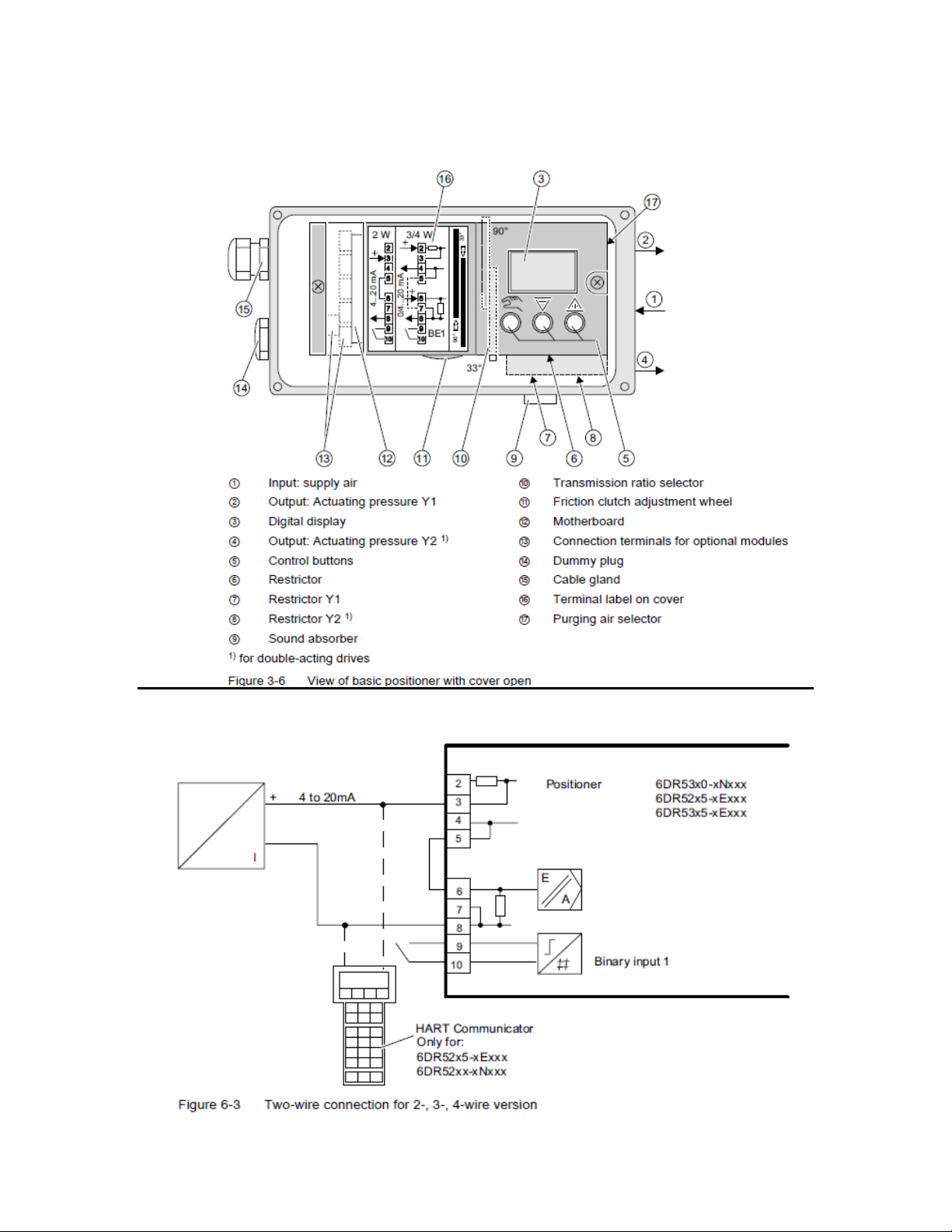
Wiring
1
Page 2
Richards Industries
Supply Pressure – Use clean, dry instrument air for the supply pressure.
• In general, on valves that are normally closed, you need 35-40 psi of supply
pressure to assure full operation.
• For valves that are normally open, 25 psi of supply pressure is generally the
most you would need to fully operate a valve of this action. You can damage
certain models by exceeding this recommendation.
• All Richards Industries linear actuators are rated for a maximum pressure of
50 psi. Please do not exceed this valve.
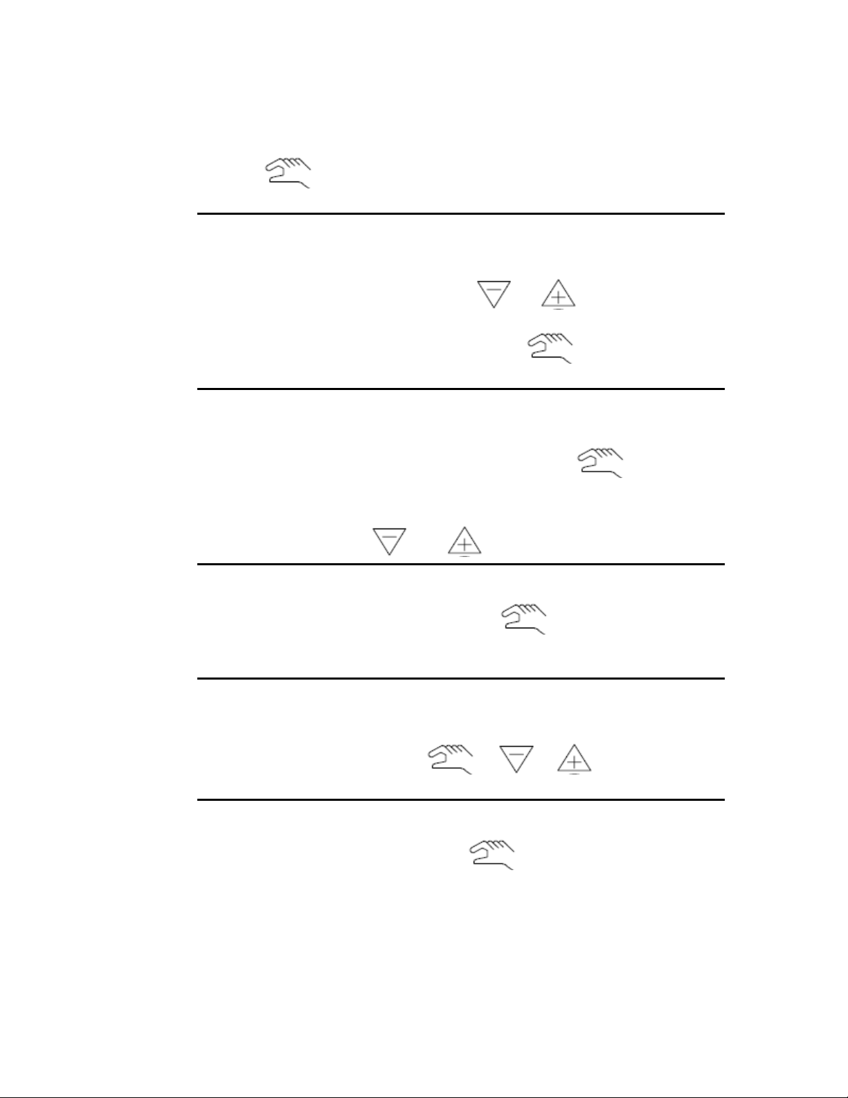
There are three keys on the positioner. Each one is described below:
- Enter Key – This key is used to move between menus and to accept changes to
the menu. It is also used to go between operating, manual, and menu modes.
- This key is used to move down in the sub-menu selections.
- This key is used to go up in the sub-menu selections.
2
Page 3
Richards Industries
Operation
• Going to Menu Mode from Automatic or Manual Mode
a. Press for 5 seconds and the menu mode will display.
• Changing a menu item
a. Once you are at a menu item, use the or keys to select the
sub-menu value you desire.
b. Once the proper value is displayed, press the key to enter and store
this value and move to the next menu item.
• Going back to Manual mode
a. Once you are finished optimizing the menu and the positioner has been re-
initialized, you exit the menu setting by pressing the key for 5
seconds.
b. The display will change and you will be in manual operation. At this
point you can use the or keys to move the valve trim.
• Going to Automatic Mode
a. From the manual mode, simply press the key momentarily to get
into automatic mode. Positioner will now respond to signal changes from
the system.
• Diagnostics
a. All diagnostic information can be accessed through the pushbuttons.
Simply press all three buttons + + at the same time
for 2 seconds to get into diagnostics.
• Exiting Diagnostics
a. To exit diagnostics, simply press the for 2 seconds to get back to
the last mode you were in.
3
Page 4

Richards Industries
Siemens PS2 Positioner Menu Effects
1. YFCT – Actuator Type
a. Turn – Only for ¼ turn valves
b. Way – Best setting for linear actuators.
c. LWay – This will also work for linear actuators, but is not as accurate as
Way.
2. YAGL – Angle Setting
a. 33º - This is used for any stroke of less than 20mm.
b. 90º - This is used for any stroke of 20mm or greater.
c. NOTE!!! Ratio selector bar must match programmed setting.
3. YWAY – Stroke Range (Optional)
a. This menu allows you to designate the stroke length. Years of experience
show that by specifically setting a distance here, you can introduce errors
into the initialization routine. It is always best to leave this setting on
OFF.
4. INITA – Automatic Initialization
a. By pressing the ‘+’ key for 5 seconds, you can start the automatic
initialization. This is the best way to initialize the positioner. Make sure
before running this that you have changed all desired menu options.
5. INITM – Manual Initialization
a. This is used for valves without hard stroke stops. At this point none of our
products fall into this category. This feature should not be used.
6. SCUR – Range Designation
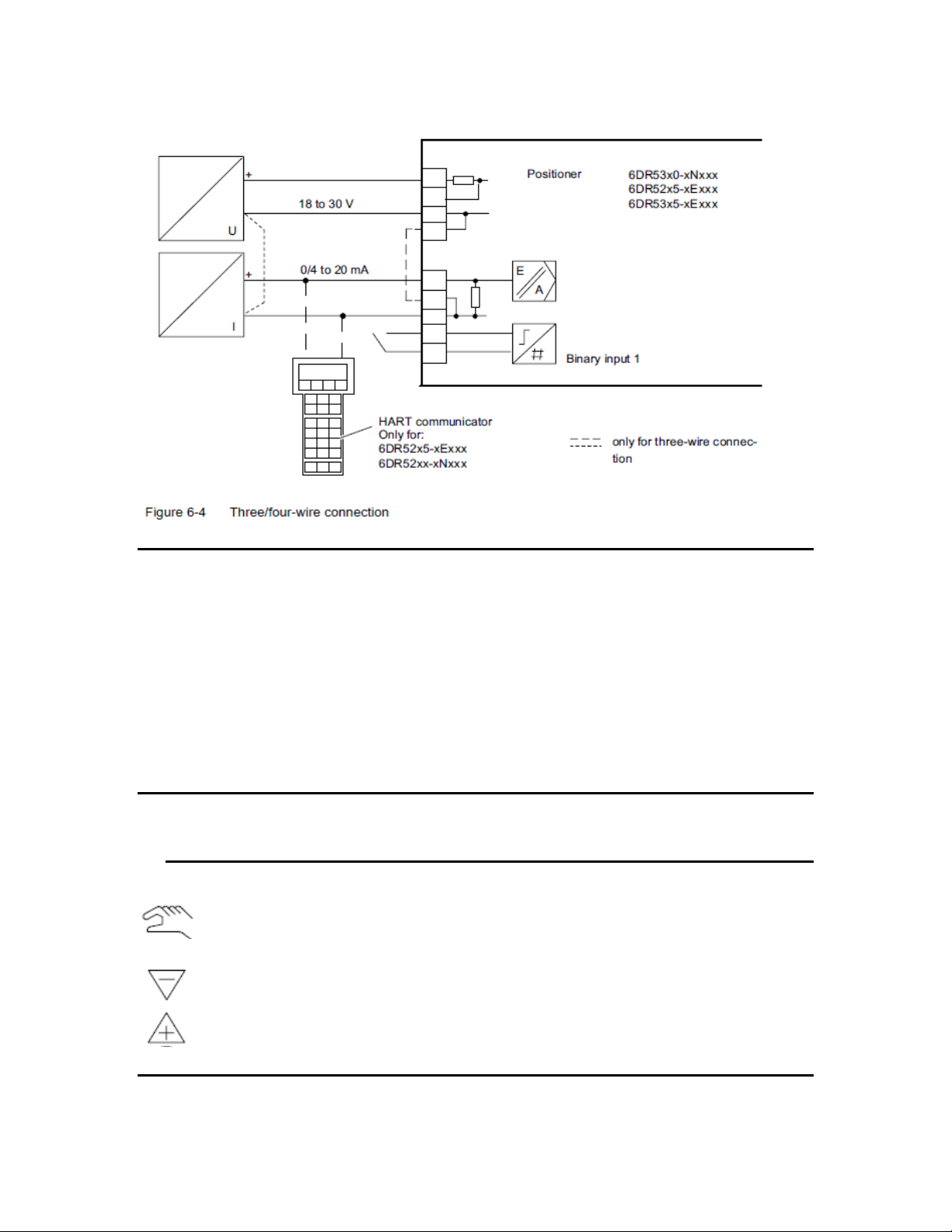
a. 0 mA – Use this setting for systems that run on 4 wire and have a 0-20 mA
output from the system. Note – If using this setting you must have a
power supply wired to the positioner. Otherwise the positioner will turn
off at any signal less than 3.8 mA.
b. 4 mA – This is the standard setting and the one that should be used for all
of our products. This allows for two wire power and a 4-20 mA signal.
7. SDIR – Setpoint Direction (Action)
a. This should be set per the customer requirements. This option changes the
way the valve responds to a signal change.
8. SPRA – Start of Split Range
a. This setting is used to signify the starting point of a split range valve. If
this were the second stage (12-20 mA), you would set this at 50% to start
moving at 12 mA of signal.
9. SPRE – End of Split Range
a. This setting is used to signify the end of the split range signal. If this were
the first stage (4-12 mA), you would set this at 50% to signify that the
range would go from 4 mA to 12 mA.
10. TSUP – Ramp Up
a. This setting is used to slow down the valve response. This setting can
dramatically decrease the speed at which the positioner moves the valve
trim. This setting is very powerful. It allows you to go from 0.0 to 400 in
seconds. This setting controls the up stroke speed.
11. TSDO – Ramp Down
4
Page 5

Richards Industries
a. This is the same as #10. This is used to slow down the downward stroke.
12. SFCT – Characteristic
a. Lin – The linear default yields a rough linear response to a change in
signal. In general, this setting will keep the trim slightly above an ideal
position. This works fine for general applications, but in critical
applications, it is better to use the freely settable characteristic based on
linear.
b. EP – This yields an equal percentage characteristic when set. Rarely used
and has three options.
c. N-EP – This yields an inverse equal percentage, or results in a quick
opening type of response. Never used and also has three options.
d. Free – This setting yields the most accurate response from the positioner.
Set it for a true linear (default values) to get the best linear response, or
slightly modify the first 4-5 points to get enhanced low flow performance.
13. through 33 – Freely Settable Points
a. These points are used to give a unique characteristic to the positioner.
Each point is programmed at 5% signal increments. You enter in the % of
stroke associated with each point. Default settings are true linear.
34. DEBA – Deadband
a. This setting is used to help keep the positioner very accurate. Default is
Automatic. In automatic the deadband actually varies as the valve
operates.
b. Using the numerical input values, the best value for this feature is 0.2. At
0.1 the positioner can be slightly unstable. This value should not be used.
Running with a fixed deadband results in better and more predictable
performance.
35. YA – Stroke Limit
a. This setting is used to bypass a portion of the stroke. On a sliding gate
valve with overlap, this can be used to ‘zero out’ the overlap. The YA
setting is manipulated on direct acting sliding gate valve to skip over the
closing band. This is entered as a percentage of stroke.
36. YE – Stroke Limit
a. This setting is used for reverse acting sliding gate valves. You would
enter in the % of stroke taken up by the overlap to fine tune the controlled
span.
37. YNRM – Position Display
a. MPOS – This value will deliver a 0-100% reading based on the hard stops
in the valve. This value is used for all globe style control valves.
b. FLOW – This value is used for sliding gate valves. It linearizes the
position display to read 0-100% from the beginning of the YA setting to
the end of the YE setting. In other words, it only shows a positive valve
position when flow is capable of running through the valve.
38. YDIR – Display Direction
a. This value changes the way the display reads. If the signal is 4-20 mA,
and the valve runs from closed to open, you would want the display to
read the same. If after initialization the positioner reads backwards, this
setting will correct that issue. This only changes the way the display
functions. It does not have any influence over how the positioner reacts.
5
Page 6

Richards Industries
39. YCLS – Tight Closing
a. No – This feature is off.
b. Up – This activates the tight closing in the upwards direction. Activates
by value set in menu item #41.
c. Do – This activates the tight closing feature to respond to the value set in
menu item #40.
d. Up/Do – This activates the tight closing feature in both directions based on
the values entered in #40 & #41.
40. YCDO – Value for Tight Closing Down
a. This parameter is represented as a percent of signal span. Setting this
value tells the positioner at what signal to dump all of the air in the
actuator and activate the tight closing down.
41. YCUP – Value for Tight Closing Up
a. This parameter is represented as a percent of signal span. Setting this
value tells the positioner at what signal to put all of the supply air in the
actuator and activate the tight closing up.
42. through 49 – Alarm and Fault Message Options
a. These are customer set for advanced users. Do not change any of these
settings when basically setting up a positioner. These will be set to
customer preferences.
50. PRST – Preset
a. This function is used to restore the positioner memory to the Siemens
factory default. These settings are not the settings we typically
recommend for our products. Please refer to the positioner programming
guide for proper settings.
b. This function is especially useful if the customer has altered the menu
settings and no one knows what has been changed. Use this to get back to
a known state.
51. XDIAG – Advanced Diagnostics
a. This menu activates a series of additional tests that can be run to optimize
the positioner performance. Modifications of items in this section are not
advised.
6
Page 7

Richards Industries
Instructions for Calibrating Siemens PS2 Positioners
Linear Valves
1. Assemble valve as normal.
2. Securely mount the take off plate and take off arm to the valve stem and secure.
3. Loosely mount the positioner to the bracket.
4. Set the ratio bar on the positioner to the proper setting for the valve stroke.
5. Lock the ratio bar with the small wheel lock located inside of the positioner. This
must be locked in the 33º position if the stroke is less than 20 mm, or 90º for
strokes longer than 20 mm.
6. Apply 35 psi to the supply port on the positioner for reverse acting valves, and 25
psi for direct acting valves.
7. Apply 4.0 mA to the proper terminals.
8. Using the ‘+ / -’ keys, move the valve to the 50% open position.
9. Adjust the position of the positioner so that the take off arm for the positioner is
parallel with the actuator and horizontal to the positioner.
10. Securely lock the positioner and bracket in place with the mounting bolts.
11. Set the friction clutch to read somewhere between 48.0 and 52.0. The closer you
get to 50.0, the more accurate the performance will be.
12. Hold the ‘Hand’ key down for 5 seconds to get into the menu mode.
13. Set the menu items as instructed on the following pages 8-10 to match the type of
valve you have.
14. Once the programming changes are made for the specific valve, run through the
automatic initialization on menu #4. Simply press and hold the ‘+’ key for 5
seconds to start the process.
15. After the initialization completes, lock down the friction clutch to prevent further
adjustment. This is done with a screwdriver in the slot below the thumb wheel.
16. Momentarily press the ‘Hand’ key to get back to the main menu.
17. If any values have changed after locking down the friction clutch, simply re-
initialize the positioner again to make sure the shift is learned by the positioner.
18. Press and hold the hand key for 5 seconds to get out of the menu mode.
19. Press the ‘Hand’ key one more time momentarily to get into Automatic mode.
20. Valve is ready for operation.
7
Page 8

Richards Industries
1)YFCT Way 1)YFCT Way 1)YFCT Way
2)YAGL
**
2)YAGL
**
2)YAGL
**
3)YWAY off 3)YWAY off 3)YWAY off
6)SCUR 4 MA 6)SCUR 4 MA 6)SCUR 4 MA
7)SDIR * 7)SDIR * 7)SDIR *
8)SPRA 0.0 8)SPRA 0.0 8)SPRA 0.0
9)SPRE 100.0 9)SPRE 100.0 9)SPRE 100.0
10)TSUP Auto 10)TSUP Auto 10)TSUP Auto
11)TSDO 0 11)TSDO 0 11)TSDO 0
12)SFCT Free 12)SFCT Free 12)SFCT Free
13)SLO 0.0 13)SLO 0.0 13)SLO 0.0
14)SL1 5.0 14)SL1 5.0 14)SL1 2.5
15)SL2 10.0 15)SL2 10.0 15)SL2 8.3
16)SL3 15.0 16)SL3 15.0 16)SL3 14.2
17)SL4 20.0 17)SL4 20.0 17)SL4 20.0
18)SL5 25.0 18)SL5 25.0 18)SL5 25.0
19)SL6 30.0 19)SL6 30.0 19)SL6 30.0
20)SL7 35.0 20)SL7 35.0 20)SL7 35.0
21)SL8 40.0 21)SL8 40.0 21)SL8 40.0
22)SL9 45.0 22)SL9 45.0 22)SL9 45.0
23)SL10 50.0 23)SL10 50.0 23)SL10 50.0
24)SL11 55.0 24)SL11 55.0 24)SL11 55.0
25)SL12 60.0 25)SL12 60.0 25)SL12 60.0
26)SL13 65.0 26)SL13 65.0 26)SL13 65.0
27)SL14 70.0 27)SL14 70.0 27)SL14 70.0
28)SL15 75.0 28)SL15 75.0 28)SL15 75.0
29)SL16 80.0 29)SL16 80.0 29)SL16 80.0
30)SL17 85.0 30)SL17 85.0 30)SL17 85.0
31)SL18 90.0 31)SL18 90.0 31)SL18 90.0
32)SL19 95.0 32)SL19 95.0 32)SL19 95.0
33)SL20 100.0 33)SL20 100.0 33)SL20 100.0
34)DEBA 0.2 34)DEBA 0.2 34)DEBA 0.2
35)YA 0.0 35)YA 0.0 35)YA 0.0
36)YE 100.0 36)YE 100.0 36)YE 100.0
37)YNRM MPOS 37)YNRM MPOS 37)YNRM MPOS
38)YDIR * 38)YDIR * 38)YDIR *
39)YCLS Do 39)YCLS Do 39)YCLS Do
40)YCDO 0.1 40)YCDO 0.1 40)YCDO 0.1
indicates required change from standard
* Set as needed for proper action and display
** 33º for strokes of 20 mm or less - 90º for strokes of 20 mm or more
Globe Style
Reverse Action
Positioner Settings
Globe Style
(High Turndown Option)
Positioner Settings
Reverse Action
Direct Action
Positioner Settings
8
Page 9

Richards Industries
1)YFCT Way 1)YFCT Way
2)YAGL
33º
2)YAGL
33º
3)YWAY off 3)YWAY off
6)SCUR 4 MA 6)SCUR 4 MA
7)SDIR * 7)SDIR *
8)SPRA 0.0 8)SPRA 0.0
9)SPRE 100.0 9)SPRE 100.0
10)TSUP Auto 10)TSUP Auto
11)TSDO 0 11)TSDO 0
12)SFCT Lin 12)SFCT Lin
34)DEBA 0.2 34)DEBA 0.2
35)YA 0.0 35)YA ***
36)YE *** 36)YE 100.0
37)YNRM FLOW 37)YNRM FLOW
38)YDIR * 38)YDIR *
39)YCLS Up 39)YCLS Do
40)YCDO 0.1 40)YCDO 0.1
indicates required change from standard
*** Per YA/YE tables following
* Set as needed for proper action and display
Positioner Settings
Positioner Settings
Sliding Gate Style
Reverse Action
Direct Action
9
Page 10

Richards Industries
Model Sizes Orifice Width Total Stroke
Stroke in mm
Set YA / YE*
70 1/4" to 3/4" 0.062 0.093 2 33%
70 1" to 1 1/4" 0.093 0.125 3 26%
70 1 1/2" to 2" 0.109 0.143 4 24%
75 1" 0.093 0.125 3 26%
75 1 1/2" 0.186 0.218 6 15%
75 2" to 3" 0.312 0.343 9 9%
75 4" 0.437 0.500 13 13%
75 6" 0.25 0.312 8 20%
701 1/2" to 3/4" 0.125 0.156 4 20%
701/702 1" to 2" 0.186 0.218 6 15%
707 1/2" 0.312 0.343 9 9%
707 3/4" 0.5 0.531 13 6%
707 1" to 2" 0.186 0.218 6 15%
711 2 1/2" to 3" 0.437 0.500 13 13%
711 4" to 6" 0.25 0.312 8 20%
* - Set YA as stated, and subtract YE from 100
Mk. 16IQ Valve Strokes - Sliding Gates
10
 Loading...