

Page 1
I & M Mark 128PQC Series
3170 Wasson Road • Cincinnati, OH 45209
Phone 513.533.5600 • Fax 513.871.0105 (f)
info@richardsind.com • www.jordanvalve.com
Warning: Jordan Valve Control Valves must only be used, installed and repaired in accordance with these Installation & Maintenance Instructions. Observe all applicable public and company codes and regulations. In the event
of leakage or other malfunction, call a qualified service person; continued operation may cause system failure or
a general hazard. Before servicing any valve, disconnect, shut off, or bypass all pressurized fluid. Before disassembling a valve, be sure to release all spring tension.
InstallatIon
Warning:
Service conditions must not exceed the limits shown
on the valve nameplate, or those outlined in this
manual. Consequences could include bursting of
pressure-retaining parts and uncontrolled process
fluid, resulting in personal injury or property damage.
Control valves should also be protected from external
damages.
Prior to installing the Mark 128PQC Series Control
Valve, perform a complete inspection for damage,
and remove any foreign debris. Position the valve for
desired flow direction. If angle flow is required, switch
the pipe plug to left-hand connection. (Figure 2)
Installation & Maintenance Instructions for the
Mark128PQC Series Control Valves
The versatility of this valve allows for installation in any
orientation, with the standard method being with the
actuator above the body. Standard orientation is best
when an angle body or angle configuration has been
specified.
When installing the valve into the line, accepted piping
practices must be used. A three-valve bypass should
be used if continuous operation is required during
inspection or maintenance.
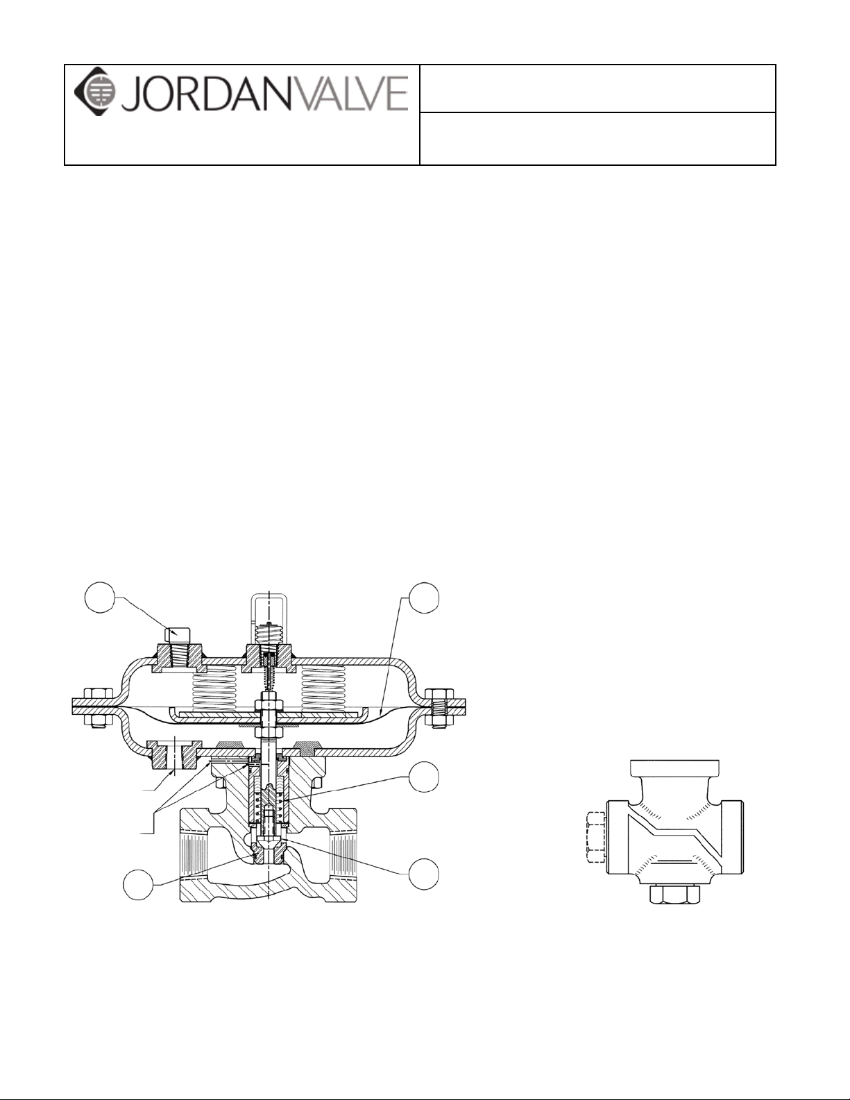
For a fail-close control valve, connect the input signal
line into the 1/4-inch NPT actuator connection (Figure
1) in the lower diaphragm case assembly. The input
signal pressure line should be installed in the upper
diaphragm case assembly of a fail-open control valve.
3
1/4 INCH NPT
PRESSURE
CONNECTION
LEAKOFF
VENTS
23
Mark 128PQC Control Valve with Fail-Close Action
Figure 1: Mark 128PQC Control Valve Typical Constructions
35
21
28
Detail of Mark 128PQC
Exterior
Page 2
Mark 128PQC SerieS Control ValVe
MaIntenance
Warning:
Prior to performing any maintenance, isolate the valve from
the process pressure. Vent control input signal pressure.
Relieve the process pressure and drain process media from
both sides of valve (Figure 5, Key 27). A sudden release
of pressure or fluid can cause personal injury or property
damage.
Scheduled inspections and maintenance are vital to continued operation of all pressure control valves and systems.
Parts are subject to wear and tear, and must be replaced
as necessary, depending on the intensity of service conditions. Unless the valve body requires maintenance or
replacement, it may remain in the pressure system or on the
vessel.
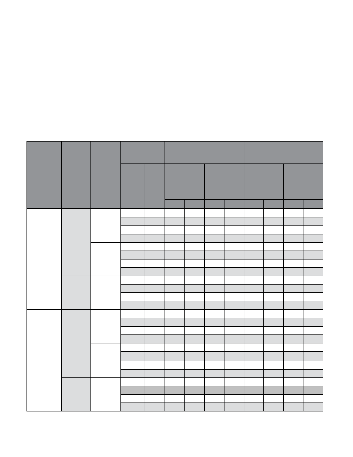
Table 1: Maximum Allowable Shutoff Pressure Drops
Cadmium Coloured Main Spring
At 20 Psig (1.4
bar) Operating
Seating
Metal
(All Types)
Soft
Actuator
Action
Fail Close
Fail
Open
Fail Close
Fail
Open
Flowing
Pressure
Drop
Tends
To:
Open
Valve
Close
Valve
Close
Valve
Open
Valve
Close
Valve
Close
valve
Port Diameter
ln mm
1/4 6.4 1510 104 3370 232 3880 233 3600 248
3/8 9.5 520 36 1340 92 1340 92 3120 215
1/2 12.7 220 15 690 47 700 48 1720 118
3/4 19.1 30 2.1 240 16 240 16 710 49
1/4 6.4 940 65 1860 128 1370 94 2920 201
3/8 9.5 1130 78 2450 169 1540 106 3300 227
1/2 12.7 1330 92 2920 201 1710 118 3600 248
3/4 19.1 2030 140 3600 248 2320 160 3600 248
1/4 6.4 170 12 350 24 --- --- --- ---
3/8 9.5 530 36 610 42 --- --- --- ---
1/2 12.7 540 37 1150 79 --- --- --- ---
3/4 19.1 1400 96 2910 200 --- --- --- ---
1/4 6.4 1000 69 1000 69 1000 69 1000 69
3/8 9.5 710 49 1000 69 1000 69 1000 69
1/2 12.7 400 28 830 57 830 57 1000 69
3/4** 19.1** 160 11 350 24 360 25 790 54
1/4 6.4 940 65 1000 69 1000 69 1000 69
3/8 9.5 1000 69 1000 69 1000 69 1000 69
1/2 12.7 1000 69 1000 69 1000 69 1000 69
3/4** 19.1** 1000 69 1000 69 1000 69 1000 69
1/4 6.4 560 39 660 45 --- --- --- ---
3/8 9.5 480 33 960 66 --- --- --- ---
1/2 12.7 540 37 1000 69 --- --- --- ---
3/4*** 19.1** 1000 69 1000 69 --- --- --- ---
Replacing Packing and Trim
Follow these procedures when replacing the entire packing and trim assembly or individually replacing packing
and trim parts. Unless otherwise indicated, key numbers in this section reference Table 2 for parts listings
for replacement packing and trim assembly, Figure 2 for
packing and trim assembly key numbers and Figure 4
control valve assembly key numbers.
1. Detach the control valve from all pressure, and
release pressure from valve body and actuator.
Ensure the valve is completely closed.
2. Remove the four nuts (Key 32) from the screws
of the lower diaphragm casing. After discon necting the input signal tubing, remove
the actuator from the valve body, along with at tached trim parts.
14A8831X012 Red Main Spring 14A9077X012
At 35 Psig (2.4
Signal
Pressure
(2 Springs
Req’d)
Psi Bar Psi Bar Psi Bar Psi Bar
bar) Operating
Signal
Pressure
(4 Springs
Req’d)
At 20 Psig (1.4
bar) Operating
Signal
Pressure
(2 Springs
Req’d)
At 35 Psig (2.4
bar) Operating
Signal
Pressure
(4 Springs
Req’d)
-2-
Page 3
Mark 128PQC SerieS Control ValVe
Replacing Packing and Trim continued,
3. Accessible areas should be cleaned at this
stage, and all necessary maintenance perf ormed. The actuator and attached trim parts
can be turned over and held by the valve body.
4. To separate trim and access packing parts or
seal O-rings, first loosen and remove the valve
plug (Key 25) and remove the packing box
washer (Key 27).
5. Remove the packing box (Key 28), O-ring
retainer (Key 18), stem O-ring (Key 19) and
diaphragm casing O-ring (Key 31) off the stem.
6. Install replacement parts as necessary.
6.1. If a complete packing and trim assem bly is being installed, remove the as sembly from the tube (Key 37), keepi ng the web sleeve (Key 39) on the
assembly so the parts remain in place.
Roll the sleeve back as necessary dur ing installation.
6.2. Continue pushing the assembly onto
the stem until the valve plug and cage
are pushed away from the packing box
washer or wiper ring. Roll the web
sleeve back into place just past the
packing box.
6.3. If installing nitrile/cotton packing, the
packing rings may be lubricated with
silicon based product.
7. Slide the packing box onto the stem until the
packing box, the O-ring (Key 19) and the O ring retainer (Key 18) and the diaphragm casi ng O-ring (Key 31) are sealed against the dia phragm casing.
7.1. Ensuring proper positioning of the O rings will prevent them from being cut
when other parts are compressed
against them.
7.2. Advance the packing spring washer
(Key 29) , packing spring (Key 21),
second packing spring washer, wiper
ring and packing box washer
(Key 27, if included in the assembly)
down onto the stem.
8. For installation of the packing and trim as
sembly, it is necessary to remove the sleeve,
cage puller (Key 40) and cage (Key 23) from
the valve plug depending on individual valve
configuration.
9. Fix the valve plug onto the stem, rotating the
plug until the shoulder makes snug contact
with the stem. No further tightening is neces sary.
10. To replace the cage or access the cage O-ring
(Key 22), remove the cage from the body (Key
26) using the cage puller or a wire hook. Re placement parts can be installed as necessary.
11. Attach the actuator and trim to the valve body
(Key 26), paying special attention to the cage
O-ring to prevent damage. Thread the four
nuts (Key 32) to the lower diaphragm casing
assembly screws. Nuts must be tightened to
15-foot-pounds (20N•m).
12. Reconnect the input signal tubing to the actua tor connection of the appropriate diaphragm
casing.
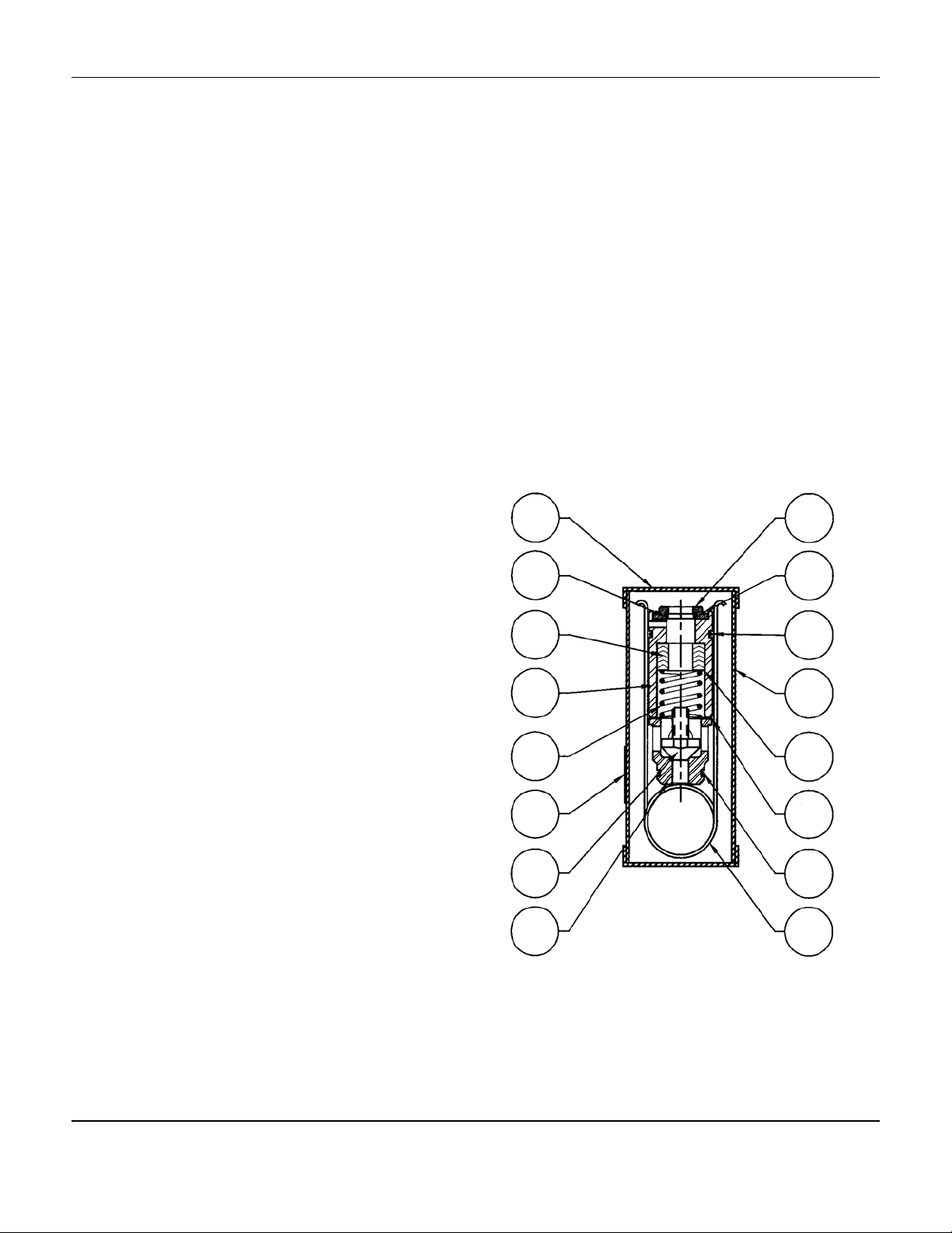
37
19
30
28
21
38
25
23
Figure 2: Replacement Packing and Trim
Assemblies for Metal Seated Constructions
18
31
20
39
29
27
22
40
-3-
Page 4

Mark 128PQC SerieS Control ValVe
Changing Main Spring Range
Unless otherwise indicated, refer to Table 2 for parts
listings for replacement packing and trim assembly,
Figure 2 for packing and trim assembly key numbers
and Figure 4 for control valve assembly key numbers.
1. Isolate off the control valve from all pressure,
and release pressure from valve body and
actuator.
2. Release pressure and drain the process
media from both sides of the valve body. En sure the valve is completely closed.
3. If necessary, disconnect the input signal tub ing; remove the diaphragm casing nuts (Key
15), cap screws (Key 14) and upper dia phragm casing (Key 1).
4. For fail-close action applications, install main
springs (Key 12), using quantities and de scriptions as outlined in Table 2.
Note: It is important to avoid loosening the
stem-nut (Key 15), as this may prevent the
valve from shutting off or from fully opening at
full pressure, and resulting in the need for
complete disassembly of the control valve to
properly install the stem and diaphragm.
5. For fail-open applications, unfasten the lock
nut (Key 16), remove the flat washer (Key
33), diaphragm (Key 35), diaphragm plate
(Key 34), spring plate (Key 2), and main
springs (Key 12).
6. Refer to Table 1 and install main springs as
indicated.
7. Reassemble the removed parts (Keys 2, 34,
35, 33, and 16). The locknut (Key 16) must
be tightened to 12 foot-pounds (16 N•m).
8. Attach the upper diaphragm casing using the
cap screws, and casing nuts, tightening in an
even crisscross pattern to avoid crushing the
diaphragm. Tighten to 15 foot-pounds
(20 N•m).
9. Reconnect the input signal tubing to the
actuator connection of the appropriate dia phragm casing.
Reversing Action or Replacing Actuator Parts
Unless otherwise indicated, refer to Table 2 for parts
listings for replacement packing and trim assembly,
Figure 2 for packing and trim assembly key numbers
and Figure 4 for control valve assembly key numbers.
1. Isolate the control valve from all pressure,
and release pressure from valve body and
actuator and ensure the valve is completely
closed.
2. Remove the input signal tubing, diaphragm
casing nuts (Key 15), cap screws (Key 14)
and upper diaphragm casing (Key 1).
3. Remove the following:
3.1. Main springs (Key 12)
3.2. Stem nut (Key 15)
3.3. Locknut (Key 16) and lock washer
(Key 4)
3.4. Spring plate (Key 2)
3.5. Diaphragm plate (Key 34) and
diaphragm (Key 35)
3.6. Flat washer (Key 33)
4. Unscrew the four nuts (Key 32) from the
screws of the lower diaphragm casing. After
disconnecting the input signal tubing,
remove the actuator from the valve body
along with attached trim parts.
5. Remove the following:
5.1. Valve plug (Key 25)
5.2. Packing box washer (Key 27)
5.3. Slide the packing box (Key 28), O ring retainer (Key 18), stem O-ring
(Key 19) and the diaphragm casing
O-ring (Key 31) off the stem.
6. Replace the valve stem, bottom stem nut or
lock nut (Key 15 or 16) as required.
7. Refer to Figure 3 and ensure that the lower
shoulder of the bottom stem nut (Key 15) (for
fail-open assembly) or locknut (Key 16) (for
fail-close assembly) is the proper distance
from the plug end of the stem.
-4-
Page 5

Mark 128PQC SerieS Control ValVe
Reversing Action or Replacing Actuator Parts
cont’d
8. Perform the following assembly sequenc es as necessary to achieve the required
control valve action:
8.1. Fail–close action: install the follow
ing parts: flat washer (Key 33),
diaphragm (Key 35), diaphragm
plate (Key 34), spring plate (Key
2), lock washer (Key 4) and stem
nut (Key 15). Tighten stem nut
to 12 foot-pounds (16 N•m).
8.2. Fail-open action, install the follow ing parts: lock washer (Key 4),
spring plate, diaphragm
plate, diaphragm, flat washer (Key
33) and locknut (Key 16). Tighten
the lock nut to 12-foot-pounds (16
N•m).
9. With fail-open application, place the main
springs (Key 12) into the lower diaphragm
casing, ensuring that the lower ends of the
springs rest over the weld stud heads of
the lower diaphragm casing.
10. Following steps 6 through 10 of the “Re-
placing Packing and Trim” section, install
packing and trim parts to secure the stem.
11. When reversing action from previous direc tion, move the vent (Key 3) to the 1/4-inch
NPT actuator connection of the lower
diaphragm casing (for fail-open action) or
upper diaphragm casing (for fail-close ac tion).
12. For fail-close application, place the main
springs so that they rest in the spring plate
holes and will not touch the upper dia-
phragm casing vent boss.
13. Mount the upper diaphragm casing, cap-
screws, and casing nuts, tightening in an
even crisscross pattern to avoid crush
ing the diaphragm. Tighten to 15
foot-pounds (20 N•m).
14. Replace the actuator and attached trim
parts into the valve body (Key 26) with nuts
(Key 15) to the lower diaphragm casing
integral assembly screws. Tighten nuts to
15 foot-pounds (20 N•m).
15. Reconnect the input signal tubing to the
actuator connection of the appropriate
diaphragm casing.
Parts orderIng
Mark 128-PQC valves have individual serial numbers,
found on the valve nameplate. Please refer to that
number when ordering parts or contacting your Jordan
Valve Sales Representative. Individual parts numbers
are listed as follows. Please include these numbers
when ordering replacement parts.
-5-
Page 6

Mark 128PQC SerieS Control ValVe
Table 2: Replacement Packing and Trim Assembly Part Numbers
TFE V-Ring Packing, Nitronic 50 SST
Valve Plug and Cage, and Inconel
X750 Packing Spring
Mark 128 PQC
Port Diameter
ln mm
TFE Ring Packing and Heat-Treated
44OC SST Valve Plug and Cage
Mark 128PQC 17-7PH SST
Packing Spring
1/4 6.5 15A2611X012 15A2611X042
3/8 9.5 15A2611X022 15A2611X052
1/2 12.7 15A2611X032 15A2611X062
2
34
4
15
Fail Close Assembly
35
A
Dimension
33
16
33
35
16
A
Dimension
34
2
4
15
Figure 3: Stem and Diaphragm Assembly Dimensions
Fail Open Assembly
Valve
Design
Mark
128PQC
Dimension A
Fail-Open Fail-Close
ln. mm ln. mm
2.72 69.1 2.46 62.5
-6-
Page 7

Mark 128PQC SerieS Control ValVe
7 8
6
5
4
3
2
1
9
10
11
12
14
35
34
33
31
30
29
28
27
26
25
Mark 128PQC Control Valve: Fail-Closed with Cage-Style Metal Seat
and Single TFE-V-Ring Packing
7 8
5
16
33
34
35
1
9
10
11
12
24
23
14
15
16
17
18
19
20
21
22
27
15
2
4
3
Fail-Open Actuator Detail
Figure 4: Typical Mark 128PQC Series Control Valve Assembly
-7-
25
Mark 128PQC Cageless
Soft-Seat Detail
Page 8

Mark 128PQC SerieS Control ValVe
Parts lIst
Key Description Part Number
1 Upper Diaphragm Casing, Steel 24A8816X012
2 Spring Plate, Zinc Plated Steel 14A8819X012
3 Vent Assembly 1C8937000A2
4 Washer, Steel 1A742328992
5 Indicator Bushing, 316 SST 13A2323X012
6 Indicator Cover, Plastic 15A1580X012
7 Travel Indicator Disc Nut, Plastic 1F730506992
8 Machine Screw, SST 14A8818X012
9 Indicator Fitting SST 15A0726X012
10 O-Ring, Nitrile 1H292606992
11 Spring, 302 SST 16A0431X012
12 Main Spring, Cadmium Plated Steel See Table 2
13 Nameplate, Aluminum 24A7156X012
14 Cap Screw, Plated Steel (2 req’d) 1E760324052
15 Hex Nut, Cadmium Plated Steel (17 req’d) 1A346524122
16 Locknut, Plated Steel 15A7591X012
17 Lower Diaphragm Casing, Steel 24A8810X012
18 O-Ring Retainer, Polyethylene Mark 128PQC 14A9053X012
19 O-Ring, Nitrile Mark 128PQC 1P420706992
20 O-Ring, Viton Mark 128PQC 1U841806382
21 Spring Mark 128PQC Inconel X750 15A1809X012
22 O-Ring, Nitrile Mark 128PQC 11A8741X012
316 SST Mark 128PQC
23 Cage
Austenitic SST w/
Tungsten Carbide
Seating Surface
24 Pipe Plug, Steel 1A794728992
Metal Seat
25 Valve Plug
Composition
Seat, Austenitic
SST/polyethylene
Mark 128PQC
Mark 128 PQC
1” Body
Mark 128 PQC
1” Body
1/4” (6.4 mm) 14A8823X022
3/8” (9.5 mm) 14A8805X022
1/2” (12.7 mm) 14A7157X022
1/4” (6.4 mm) 15A6800X012
3/8” (9.5 mm) 15A6801X012
1/4” (6.4 mm)
and 3/8” (9.5
mm) port
1/2” (12.7 mm)
port
1/4” (6.4 mm) through 1/2” (12.7 mm) port 15A3199X012
3/4” port 15A3197X012
316 SST 16A2087X012
Austenitic SST w/
Tungsten Carbide
Seating Surface
316 SST 14A6618X012
15A6804X012
Valve Plug Stem, 316 SST 1” Body, Mark 128PQC 14A8806X012
26 Valve Body, WCB Steel 1” NPT, Mark 128PQC 24A8802X012
27 Packing Box Washer, SST 1/2” (12.7 mm) or smaller port 14A6617X012
3/4” (19.1 mm) port 14A8807X012
28 Packing Box, SST Mark 128PQC 14A8809X012
29 Washer, SST (2 req’d) Mark 128PQC 14A8808X012
-8-
Page 9

MK128PQCIM/0314/2K
Mark 128PQC SerieS Control ValVe
Parts lIst cont.
Key Description Part Number
Complete Set 14A8812X012
30 Packing Set, TFE Mark
128PQC
31 O-Ring, Nitrile 13A1584X012
33 Washer, Cadmium Plated Steel 14A9770X012
34 Diaphragm Plate, Zinc Plated Steel 14A8814X012
35 Diaphragm, Neoprene w/nitrile insert 14A8813X012
37 Paper Tube ---
38 Paper Label ---
39 Protective Sleeve-Web ---
40 Cage Puller 15A2525X012
Keys 5, 7, 8, 9, 10, 11
Complete Assembly 35A1588X0A2
Individual
Parts
Male Adaptor 1J227206242
V-Ring (4 req’d) 1J255206992
Female Adaptor 1J233201012
Wiper Ring 1R2516X0012
Jordan Valve, a division of Richards Industries
3170 Wasson Road • Cincinnati, OH 45209
513.533.5600 • 800.543.7311 • 513.871.0105 (f)
info@richardsind.com • www.jordanvalve.com
 Loading...