

Page 1
I & M 657M Series
3170 Wasson Road • Cincinnati, OH 45209
Phone 513.533.5600 • Fax 513.871.0105 (f)
info@richardsind.com • www.jordanvalve.com
Warning: Jordan Valve Control Valves must only be used, installed and repaired in accordance with these Installation & Maintenance Instructions. Observe all applicable public and company codes and regulations. In the event
of leakage or other malfunction, call a qualified service person; continued operation may cause system failure or
a general hazard. Before servicing any valve, disconnect, shut off, or bypass all pressurized fluid. Before disassembling a valve, be sure to release all spring tension.
IntroductIon
All Jordan Valve equipment, including actuators, are
to be installed and maintained in accordance with
instructions supplied by Jordan Valve. Only qualified
personnel may install and service the actuator, and, if
necessary, contact a gas service person.
InstallatIon
The 657M Diaphragm Actuator is usually delivered
furnished mounted on a Jordan valve body. When
installing the valve body into the pipeline, consult the
instructions for that particular valve body. Should you
have any questions during the installation procedure,
consult your Jordan Valve representative.
The loading pressure is connected to the NPT connection in the top of the diaphragm case (1/4” for sizes 30
through 60, 1/2” size 70). With larger sizes, it may be
beneficial to reduce the connection down to 1/4”. Pipe
or tubing may be used, and should be run to the output pressure connection on the automatic controller.
Avoid transmission lag in the control signal by keeping
the length of pipe or tubing as short as possible. When
long distances are involved, install a valve positioner
on the actuator. If the valve positioner is provided as
part of the original equipment, the loading pressure
connection will be made at the Jordan Valve manufacturing facility.
If the 657M Diaphragm Actuator is shipped alone for
field mounting, it should be mounted onto the valve
body and secured in place with the yoke locknut.
Clamp the actuator stem and valve plug stem together
using the stem connector to provide the proper valve
travel. Refer to the “Assembly Instructions” section of
this manual for complete instructions.
Installation & Maintenance Instructions for the
657M Series Diaphragm Actuator
above for accessibility. Ensure that sufficient room is
provided below should removal of the actuator and
valve plug be necessary.
operatIon and adjustment
Refer to the nameplate on the yoke of the actuator
for details on the specific construction and operating
range. The requirements of your specific application
will dictate the spring and diaphragm used in your
657M Actuator. When in service, the actuator will create
full travel of the valve plug when diaphragm pressure is
applied according to the range indicated on the name
plate. Generally, the diaphragm pressure range is 3 to
15 PSI or 6 to 30 PSI, but other ranges may be used.
Pressure within the valve body creates forces on the
valve plug which directly affect the actual operating
diaphragm pressure range. When pressure conditions
in the valve body are different from those indicated in
the factory settings, the valve may not stroke completely
over the indicated range. To achieve correct travel for
the diaphragm pressure range utilized, a simple spring
adjustment is necessary. Note, however, that the actuator spring has a fixed pressure span and that adjustment of the spring compression simply shifts this span
up or down to make the travel of the valve correspond
with the diaphragm pressure range.
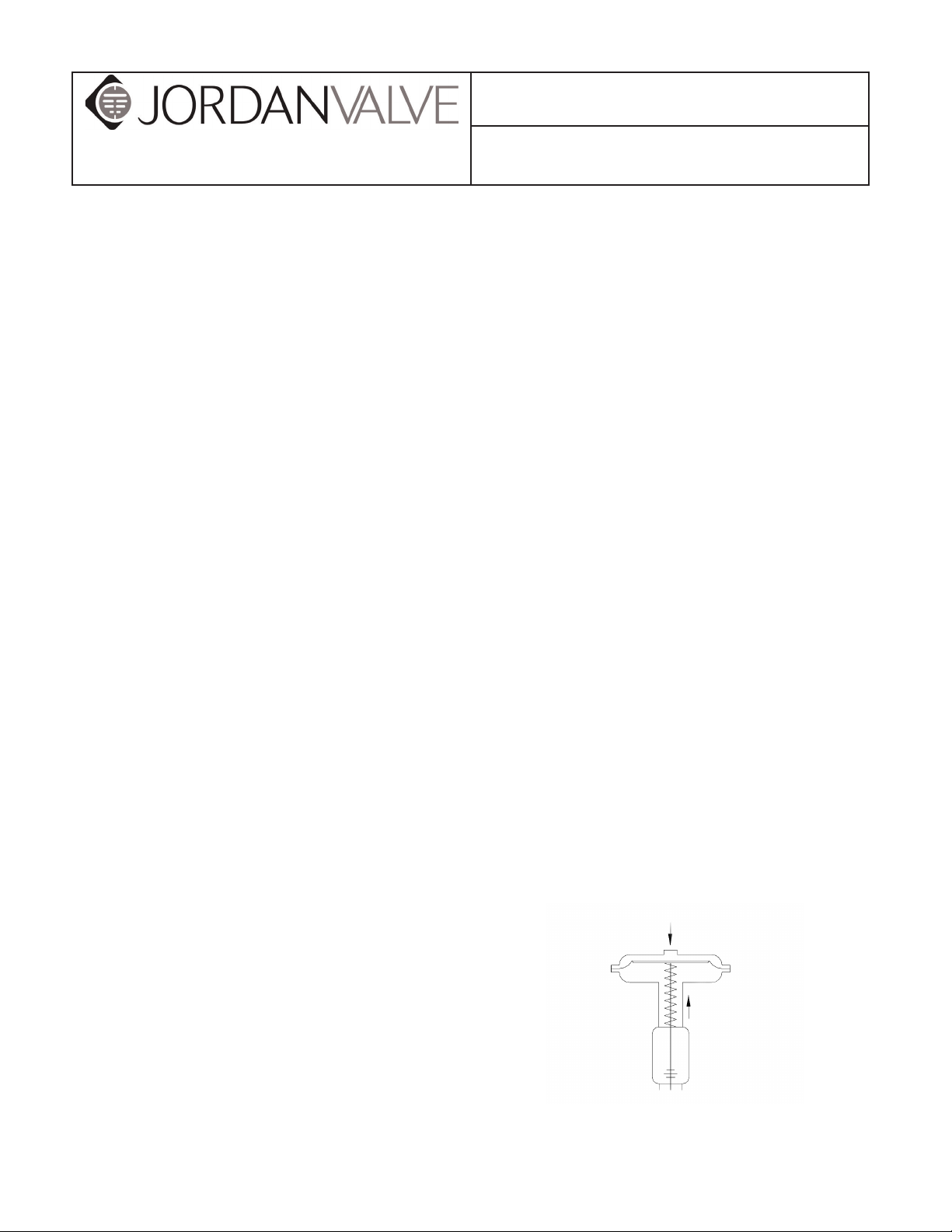
657M Direct Acting Diaphragm Actuator
Air Pushes Down
Spring Lifts
For ease of service, ensure that the control valve is
located for easy access and serviceability with room
Stem moves upward with loss of
operating medium
Figure 1: Schematic of 657M Actuator
Page 2

657M SerieS DiaphragM actuator
Operation and Adjustment Continued,
The Jordan Valve nameplate indicates a “bench set”
pressure range in addition to a standard diaphragm
pressure range. The “bench set” pressure range indicates the range required to completely stroke the valve
with out any pressure in the valve body, for example
as if the valve were being tested on the work bench.
While In service, however, with the specified pressure
drop applied across the valve, it should stroke over the
standard diaphragm pressure range as indicated on the
nameplate.
Once the control valve has been installed and connected to the controller, it should be tested for correct travel,
lack of friction and correct action (air-to-open or air-toclose) to match the controlling instrument. To ensure the
most effective operation, the actuator stem and the valve
plug stem must move freely when responding to the
loading pressure change on the diaphragm.
Disassembly Instructions
Although the following instructions describe how the
657M Diaphragm Actuator can be completely disassembled, when inspection or repairs are required, only
disassemble those parts required to accomplish the job.
Consult Figure 3, and proceed as follows for
disassembly:
1. Bypass the control valve and exhaust any actua tor loading pressure to atmospheric. Discon-
nect the actuator supply line and any
leakoff piping.
2. Relieve all pressure from the spring by threading
the spring adjuster (key 2) out of the yoke.
3. To remove the valve body from the actuator,
separate the stem connector (key 21)
and remove the yoke locknut.
4. Loosen the stem locknuts (keys 13 and 14),
remove the two cap screws and separate the
stem connector.
5. Loosen the diaphragm case cap screws and
nuts (keys 19 and 20) and remove the
upper diaphragm case.
6. Remove the molded diaphragm (key 6).
7. Extract the diaphragm plate and actuator stem
(keys 5 and 3) as an assembly. These parts can
be further separated if required.
8. Remove the actuator spring (key 1) and spring
seat (key 4).
9. If necessary, remove the lower half of the dia-
phragm case (key 8) by loosening the
cap screws.
10. Removing the spring adjuster will complete the
disassembly.
Assembly Instructions
1. The 657M Actuator can be assembled
in the reverse order of the disassembly
instructions. These additional steps below will
assist with proper assembly and continued
operation.
2. Apply lubricant to the threads and spring seat
bearing surface of the spring adjuster (See loca tion marked “LP” on Figure 3).
3. Ensure that the spring seats and the lower seat
align properly and rest against the diaphragm
plate.
4. Use a criss-cross pattern to evenly tighten the
nuts on the casing bolts.
5. If the stem locknuts were removed during disas-
sembly, install them onto the valve plug stem
and place the travel indicator (key 12) with the
cupped side downward.
6. Secure the actuator onto the valve body using
the yoke locknut.
7. Assemble the stem connection as follows
according to the required action:
a. Mounted on Body with “Push Down to
Close” Valve Plug
i. When the body is assembled
and the actuator is mounted,
ensure the valve plug is in the
closed position.
ii. Once the locknuts are secured
onto the stem, set the travel
indicator disc onto the locknuts
with the cupped portion
facing downward.
iii. Raise the valve plug off of the
seat, with the travel specified on
the nameplate, or, pressure the
actuator until the stem
moves down the specified valve
travel.
iv. Install the stem connector by
clamping the actuator
stem to the valve stem.
v. Raise the indicator disc to the
stem connector, using
the locknuts to tighten in
position.
-2-
Page 3
657M SerieS DiaphragM actuator
vi. Ensure that the desired total
travel is available by cycling the
actuator. This will also
demonstrate that the valve
plug seats properly. If
necessary, minor travel
adjustments can be made
by slightly loosening the stem
connecter, tightening the
locknuts and screwing the
stem either into or out of the
stem connecter using a wrench
on the locknuts.
vii. Once the valve travel has been
accomplished, secure
the stem connector, lock
the travel indicator disc
against the connector
using the locknuts, and
adjust the travel indicator scale
(key 16) to show
valve plug position.
viii. Using a gauge, measure the
pressure delivered to
the actuator. Make any
adjustments on the actuator, or
the positioner,
to set the starting point of
valve travel and ensure
full range of travel as desired.
vi. Apply loading pressure to the
diaphragm case and move the
valve plug down off of its seat.
vii. Rotate the valve plug stem into
the stem connector
approximately 1/8”. Slightly
tighten the stem lock
nuts to move the travel indicator
to the proper position.
viii. Check the availability of desired
travel by fully cycling the actua-
tor. The valve plug should seat
before the upper travel stop. If
required, minor adjustments to
total travel can be made
by slightly loosening the
stem connector, tightening the
locknuts and screwing the stem
either into or out
of the stem connector
using a wrench on the locknuts.
Note: When making adjustments to the valve stem,
do not rotate the valve stem more than the 1/8” that it
was screwed into the actuator stem in step “vii”. Over
rotating the valve stem will prevent the valve from
shutting off.
ix. Proceed with steps “vii” and
“viii” as in section “A” above.
b. Mounted on Body with “Push Down to
Open” Valve Plug
i. Attach the locknuts to the stem
and set the travel indicator disc
into position.
ii. Raise the valve plug to the
closed position. On larger body
sizes, a pry bar may be inserted
through the body line flange
opening. If the valve is located
in a pipeline application,
you may remove
the bottom flange and raise the
valve plug from below.
iii. Install the stem connector and
ensure that the actuator
stem threads are fully engaged.
iv. Install the two cap screws in the
stem connector to clamp the
actuator stem to the valve stem.
v. If a pry bar has been used,
remove it now. If the
bottom flange has been
removed, replace it now.
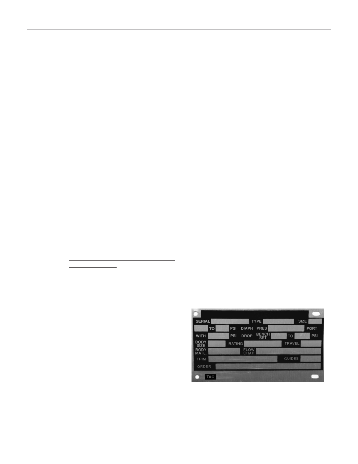
Serial Number
Each 657M Actuator has a serial number, stamped on
the nameplate. When corresponding with your Jordan
Valve representative, always refer to that serial number
when requiring replacement parts or technical information.
Figure 2: Nameplate on 657M Actuator
-3-
Page 4

657M SerieS DiaphragM actuator
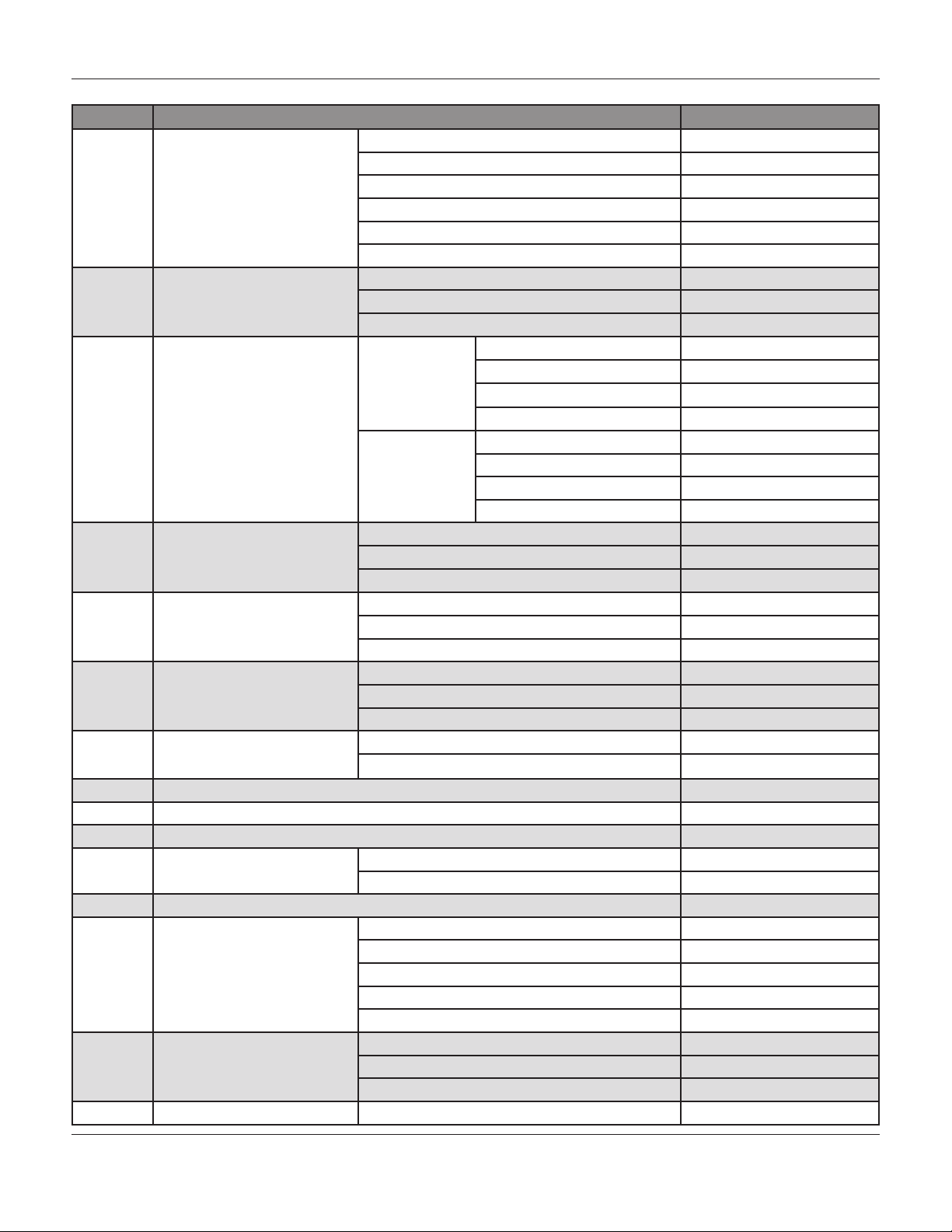
657m actuator parts lIst
The following parts list includes complete part numbers
for components of the 657M Actuator that are generally replaceable in the field, and are most commonly
used. Key numbers correspond to those in Figure 3. If
materials and parts are required, but are not outlined in
this literature, consult your Jordan Valve representative.
Include the serial number of your actuator in all correspondence regarding replacement parts.
657m actuator
Figure 3: 657M Actuator Assembly Drawing
Table 1: Parts Reference
Key Part Name
1 Actuator Spring
2 Spring Adjuster
3 Actuator Stem
4 Spring Seat
5 Diaphragm Plate
6* Diaphragm
7 Upper Diaphragm Case
8 Lower Diaphragm Case
9 Yoke
10 Cap Screw
11 Cap Screw
12 Travel indicator
13 Hex Nut
14 Hex Jam Nut
15 Self-Tapping Screw
16 Travel Indicator Scale
17 Nameplate
18 Drive Screw
19 Cap Screw
20 Hex Nut
21 Stem Connector
22 Twin Speed Nut (not shown)
23 Pipe Bushing (Size 70 only)
(Not shown)
*Recommended Spare Part
-4-
Page 5

657M SerieS DiaphragM actuator
Table 2: Parts List
Key Description Part Number
1 Actuator Spring Consult Jordan Valve
Size 30 1E792924102
2 Spring Adjustor
3 Actuator Stem
Steel, CD PL
4 Lower Spring Seat
5 Diaphragm Plate
Cast Iron
6 Diaphragm Nitrile
7 Upper Diaphragm
Casing Steel
8 Lower Diaphragm
Casing Steel
Sizes 34, 40 1E807324102
Sizes 45, 46, 50, 60 1E832624102
Size 70 1N129724102
Size 30 1E792824102
Size 34 1E872924102
Size 40 1E807124102
Sizes 45, 46 1J332924102
Sizes 50, 60 1E832424102
Size 70 Up to 2” Travel 1N129424102
Over 2” Travel 1N132524102
Size 30, Steel 1U425623122
Sizes 34,40, Steel 1R179923122
Sizes 45, 46, 50, 60, Steel 1R180023122
Size 70, Cast Iron 1N129619052
Size 30 2E880419042
Sizes 34,40 3E880519042
Sizes 45, 50 2E831519042
Sizes 46, 60 2E847519042
Size 70 2N127019042
Size 30 2E791902202
Sizes 34, 40 2E670002202
Sizes 45, 50 2E859502202
Sizes 46, 50 2E859702202
Size 70 2N126902202
Size 30 2E791528992
Sizes 34, 40 2E806028992
Sizes 45, 50 3E830928992
Sizes 46, 50 2E847228992
Size 70 2N126628992
Size 30 2E792225062
Sizes 34, 40 2E806325062
Sizes 45, 50 3E831625062
Sizes 46, 50 2E847425062
Size 70 2N127125062
-5-
Page 6
657M SerieS DiaphragM actuator
Table 2: Parts List, continued
Key Description Part Number
Size 30 3E792619042
Size 34 2E869619042
9 Yoke
Cast Iron
Cap Screw
10
11 Cap Screw
12 Travel Indicator, SST
13 Hex Nut, SST
14 Hex Jam Nut, SST
15 Self-tapping Screw, SST Sizes 30, 34, 45, 46 (2 req’d) 11793238992
16 Travel Indicator Scale, SST See following Table 4
17 Nameplate, SST 12B6508X0A2
18 Drive Screw, SST (4 req’d) 1A368228982
19 Cap Screw,
20 Hex Nut, Standard 3/8” Nut 1” Nut
21 Stem Connector, STL
22 Twin Speed Nut, SST
23 Pipe Bushing, Steel, PL Size 70 1C379026232
Steel, CD PL
Standard 3/8” Bolt
Size 40 3E807019042
Sizes 45, 46 2E903719042
Sizes 50, 60 3E832319042
Size 70 3N127319042
Size 30 1E798032982
Sizes 34, 40 1E760432992
Sizes 45, 46, 50, 60, 70 1E775432982
Size 30 (6 req’d) 1D529824052
Push Down to
Close Valve
Push Down to
Open Valve
Sizes 30, 34 1E793138992
Sizes 40, 45, 46 1E807238992
Sizes 50, 60, 70 1B832838992
Sizes 30, 34 (2 req’d) 1P131224142
Sizes 45, 46 (2 req’d) 1A413224122
Sizes 50, 60, 70 1A375424122
Size 40 1A353724122
Sizes 45, 46 (2 req’d) 1A353724122
Sizes 50, 60, 70 1A351124122
Sizes 50, 60, 70 (2 req’d) 1E831338992
Size 30, 34, 40, 45, 50, 60 1” bolt
Size 70 1-1/4” bolt
Sizes 30, 34 1E7977000A2
Size 40 1F659225142
Sizes 45, 46 1J3330000A2
Sizes 50, 60 1E8337000A2
Size 70 1H8655000A2
Sizes 30, 34 1E793938992
Sizes 40, 45, 46 1E808438992
Sizes 50, 60, 70 1E833538992
Sizes 34, 40 (6 req’d) 1A368424052
Sizes 45, 46, 50, 60 (8 req’d) 1A368424052
Size 70 1N129328992
Size 30 (3 req’d) 1D368424052
Sizes 34, 40 (3 req’d) 1A368424052
Sizes 45, 46, 50, 70 (4 req’d) 1A368424052
Size 70 (9 req’d) 1N129328992
-6-
Page 7

657M SerieS DiaphragM actuator
Table 3: Travel Indicator Scale
Actuator
Size
30, 34 1E793638992
40, 45, 46 1E808138992
50, 60 1E833138992
70 1E833138992
Table 4: Thrust Capabilities by Input Signal Range
Travel
mm Bar N
19
29
38
51 70 0.2-1 7930
Inch Psig Lb
3/4
1-1/8
1-1/2
2 70 3-15 1760
3/4" Travel 1-1/8" Travel 1-1/2" Travel 2" Travel 3" Travel
1E808228992 1E808338992 1R444538982
1E833128992 1E833338992 1E833428992
1E833238992 1E833338992 1E833438992 1N129838992
Pressure Range to
Actuator Size
30 0.2-1 2250
34 0.2-1 3380
40 0.2-1 3380
45 0.2-1 4670
46 0.2-1 6940
50 0.2-1 5140
60 0.2-1 6940
30 3-15 506
34 3-15 759
40 3-15 759
45 3-15 1050
46 3-15 1560
50 3-15 1155
60 3-15 1560
Actuator
Diaphragm
0.4-2 3890
0.4-2 5830
0.4-2 5530
0.4-2 8410
0.4-2 13,190
0.4-2 8410
0.4-2 13,190
0.4-2 18,590
6-30 874
6-30 1311
6-30 1242
6-30 1890
6-30 2964
6-30 1890
6-30 2964
6-30 4180
Thrust Capabilities
657MIM/0214/2K
Part Numbers
Jordan Valve, a division of Richards Industries
3170 Wasson Road • Cincinnati, OH 45209
513.533.5600 • 800.543.7311 • 513.871.0105 (f)
info@richardsind.com • www.jordanvalve.com
 Loading...