


User's Manual
DP100 Series
Receipt Printer

DP100 User’s Manual
- i -
Important Safety Instruction
Be sure to have read the manual carefully before your operation. Neither our Corporation nor its
affiliates shall be liable to the purchaser of this product or third parties for damages, losses, costs,
or expenses incurred by purchaser or third parties as a result of: accident, misuse, or abuse of this
product or unauthorized modifications, repairs, or alterations to this product, or failure to strictly
comply with our Corporation’s operating and maintenance instructions.
z Follow all warnings and instructions in the manual as well as marked on the product.
z Unplug this product from the wall outlet before cleaning. Do not use liquid or aerosol cleaners.
Use a damp cloth for cleaning.
z Do not use this product near water.
z Be sure to set this equipment on a firm, stable, horizontal surface. The product may break or
cause injury if it falls.
z Slots and opening on the cabinet and the back or bottom are provided for ventilation. To
ensure reliable operation of the product and to protect it from overheating, do not block or
cover these openings. The openings should never be blocked by placing the product on a bed,
sofa, rug or other similar surface. This product should not be placed in a built-in installation
unless proper ventilation is provided.
z This product should never be placed near or over a radiator or heat origin, and should avoid
of direct sunshine.
z Do not locate this product where the cord will be walked on. When the cord or the plug is
mangled, please stop using and get a new one replaced. Make sure the old one is far away
from the printer, so it can avoid someone who does not know the inside story getting damage.
z Be sure to use the specified power source. Connection to an improper power source may
cause fire or shock.
z Do not use in locations subject to high humidity or dust levels. Excessive humidity and dust
may cause equipment damage or fire.
z Never push objects of any kind into this product though cabinet slots as they may touch
dangerous voltage dots or short out parts.
z Don’t remove the printer’s out-cover and repair the printer. When needed, call or take it to the
professional.
z If water or other liquid spills into this equipment, unplug the power cord immediately, and then
contact your dealer or a service center for advice.
z To ensure safety, please unplug this product prior to leaving it unused for an extended period.
The wall outlet you plan to connect to should be nearby and unobstructed.
z Unplug this product from the wall outlet and refer servicing to qualified service personnel
under the following conditions:
A. When the power cord or plug is damaged or frayed.
B. If liquid has been spilt into the product.
C. If the product has been exposed to rain or water.
D. If the product does not operate normally when the operating instructions are followed.
Adjust only those controls that are covered by the operating instructions since importer
adjustment of other controls may result in damage and will often require extensive work by
a qualified technician to restore the product to normal operation.
E. If the product has been dropped or the cabinet has been damaged.
F. If the product exhibits a distinct change in performance, it indicates a need for service.
Note: The contents of this manual may be changed without prior notice.
* All parts of the printer can be recycled. When it is abandoned, we can call it back
freely. Please contact us when you abandon it.

DP100 User’s Manual
- ii -
Overview
DP100 is the new-style printer with high quality performance, 24-pin and 40-column for bill
printing.
DP100 is ideal for a wide range bill printing requirements, especially for all kinds of instruments
and the industries of post & telecom, business, transportation and finance.
According to the paper types or different data ports (interface), the series of DP100 is divided
into several different names:
1. Tractor paper model and roll paper model, roll paper model add “F” to distinguish.
2. Parallel interface, serial interface, and USB interface model, serial interface add “S” to
distinguish, and USB interface add “U”.
MODEL DESCRIPTION REMARK
DP100 Tractor Paper\Parallel Interface Model
DP100S Tractor Paper\Serial Interface Model
DP100U Tractor Paper\USB Interface Model
DP100UE Tractor Paper\USB+Ethernet Interface Model
Load paper by the tractor. This
printer model can use the tractor
paper (width: 76~142mm).
DP100F Roll Paper\Parallel Interface Model
DP100FS Roll Paper\Serial Interface Model
DP100FU Roll Paper\USB Interface Model
DP100FUE Roll Paper\USB+Ethernet Interface Model
Load paper by the paper ladle.
This printer model can use the roll
paper (width: 57.5mm, 76mm or
114mm).
3. This series can also be equipped with cash drawer interface.
Note: Please contact your local dealer to replace the interface with payment if you need.
Features
z Use the high quality 24-pin print head, high reliability, and long life.
z Include GB18030 national standard Chinese character set,and support four bytes
Chinese character printing out.
z With cash drawer interface, support two cashboxes, especially for market charge system.
z With Black Mark Function.
z Multi-emulation: EPSON ESC/PK2, ESC/POS, STAR 320.
z Build-in the bar code generator, supports EAN 8/13, NW7, Code 39, Industrial 2 of 5,
Interleaved 2 of 5, Matrix 2 of 5, Code 128B/C.
z With pin-broken compensation function
z With pin- exchange printing function

DP100 User’s Manual
- iii -
Contents
Important Safety I
nstruction............................................................................................................ i
Overview .......................................................................................................................................... ii
Chapter 1 Inst
allation...................................................................................................................... 1
1.1 Unpacking................................................................................................................................ 1
1.2 Unpacking the Protective Materials.......................................................................................... 1
1.3 Identifying Main Par
ts of the Printer......................................................................................... 2
1.4 Installing the Ribbo
n Cartridge................................................................................................. 2
1.5 Installing and Uninstalling the
Top Cover ................................................................................. 4
1.5.1 Installing the Top Cover..................................................................................................... 4
1.5.2 Uninstalling t
he Top Cover................................................................................................. 4
1.6 Connecting the Computer or Ot
her Equipment ........................................................................ 4
1.6.1 Connecting the Cas
h Drawer Cable.................................................................................. 4
1.6.2 Connecting the Parallel Interface Cable
............................................................................ 5
1.6.3 Connecting the USB Interface Cable
................................................................................. 5
1.6.4 Connecting the Serial Interface Cable
............................................................................... 5
1.6.5 Connecting the Ethernet Interfa
ce Cable........................................................................... 6
1.7 Connecting the Power Source ................................................................................................. 6
1.8 Installing t
he Driver .................................................................................................................. 7
1.9 Network settings ...................................................................................................................... 9
1.9.1 Connecting Printer
............................................................................................................. 9
1.9.2 Setting IP Address............................................................................................................. 9
1.9.3 Installing Print
er Network Driver...................................................................................... 12
Chapter 2 Control
Panel ............................................................................................................... 19
2.1 Control Panel ......................................................................................................................... 19
2.1.1 Function Keys.................................................................................................................. 19
2.1.2 Shortcut Keys..................................................................................................................19
2.1.3 Indicator LED .................................................................................................................. 20
2.1.4 Set the Print Speed, the Top of
Form and the Tear-off Position....................................... 21
2.2 To Print the Current
Setting Report ........................................................................................ 21
2.3 To Enter the Setup Menu Sys
tem and Change the Settings .................................................. 23
2.4 Description of Options ........................................................................................................... 24
2.5 Online-aptitude Para
meter Settings....................................................................................... 25
2.6 Using the Self Test Functions ................................................................................................ 26
Chapter 3 Loadi
ng Paper.............................................................................................................. 29
3.1 Paper Thickness Adjustment.................................................................................................. 29
3.2 Top of Form Adjustment Mode ............................................................................................... 29
3.3 Loading the T
ractor Paper ..................................................................................................... 29
3.4 Loading the Roll Paper
.......................................................................................................... 31
Appendix A Maintenance and T
roubleshooting.......................................................................... 33
A.1 Maintenance.......................................................................................................................... 33
A.2 Error LED on the Co
ntrol Panel............................................................................................. 33

DP100 User’s Manual
- iv -
A.3 Troubleshooting..................................................................................................................... 34
Appendix B Speci
fications ........................................................................................................... 36
B.1 Basic Specification ................................................................................................................ 36
B.2 Printable A
rea........................................................................................................................ 38
Appendix C Command Code
Summary ....................................................................................... 39
C.1 Introduction ........................................................................................................................... 39
C.2 ESC/PK2 Command Codes
................................................................................................... 39
C.3 ESC/POS Command
Codes.................................................................................................. 41
C.4 STAR320 Command Codes
.................................................................................................. 42
C.5 ESC/PK2 Commands Desc
ription ......................................................................................... 42
Printer Operating Commands
................................................................................................... 43
Paper Input Comman
ds............................................................................................................ 43
Data Control Commands.......................................................................................................... 44
Page Mode Setting Commands
................................................................................................ 44
Line Spacing Command
s ......................................................................................................... 45
Orientation Setting Commands
................................................................................................ 46
Print Position Command
s......................................................................................................... 47
Font Enhancement Commands
................................................................................................ 48
Print Effect Comman
ds............................................................................................................. 50
Character Commands
.............................................................................................................. 52
Graphic Mode Printing Comman
ds........................................................................................... 52
Chinese Character P
rinting Commands ................................................................................... 53
C.6 ESC/POS Commands Desc
ription ........................................................................................ 58
C.7 Parts of STAR320 Compatible Commands D
escription......................................................... 60
Paper Feed Comman
ds ........................................................................................................... 61
Data Control Commands.......................................................................................................... 61
Page Mode Setting Commands
................................................................................................ 62
Line Spacing Command
s ......................................................................................................... 63
Orientation Setting Commands
................................................................................................ 64
Print Position Command
s......................................................................................................... 64
Font Enhancement Commands
................................................................................................ 65
Character Proces
sing Commands............................................................................................ 66
Barcode Commands
................................................................................................................. 66
Appendix D I
nterface .................................................................................................................... 68
D.1 Cash Drawer Interface .......................................................................................................... 68
D.2 Parallel I
nterface ................................................................................................................... 68
D.3 USB Interface........................................................................................................................ 70
D.4 Serial Interface ...................................................................................................................... 71
D.5 Ethernet Interface.................................................................................................................. 72
Appendix E B
lack mark ................................................................................................................ 73
DP100 User’s Manual
- 1 -
Chapter 1 Installation
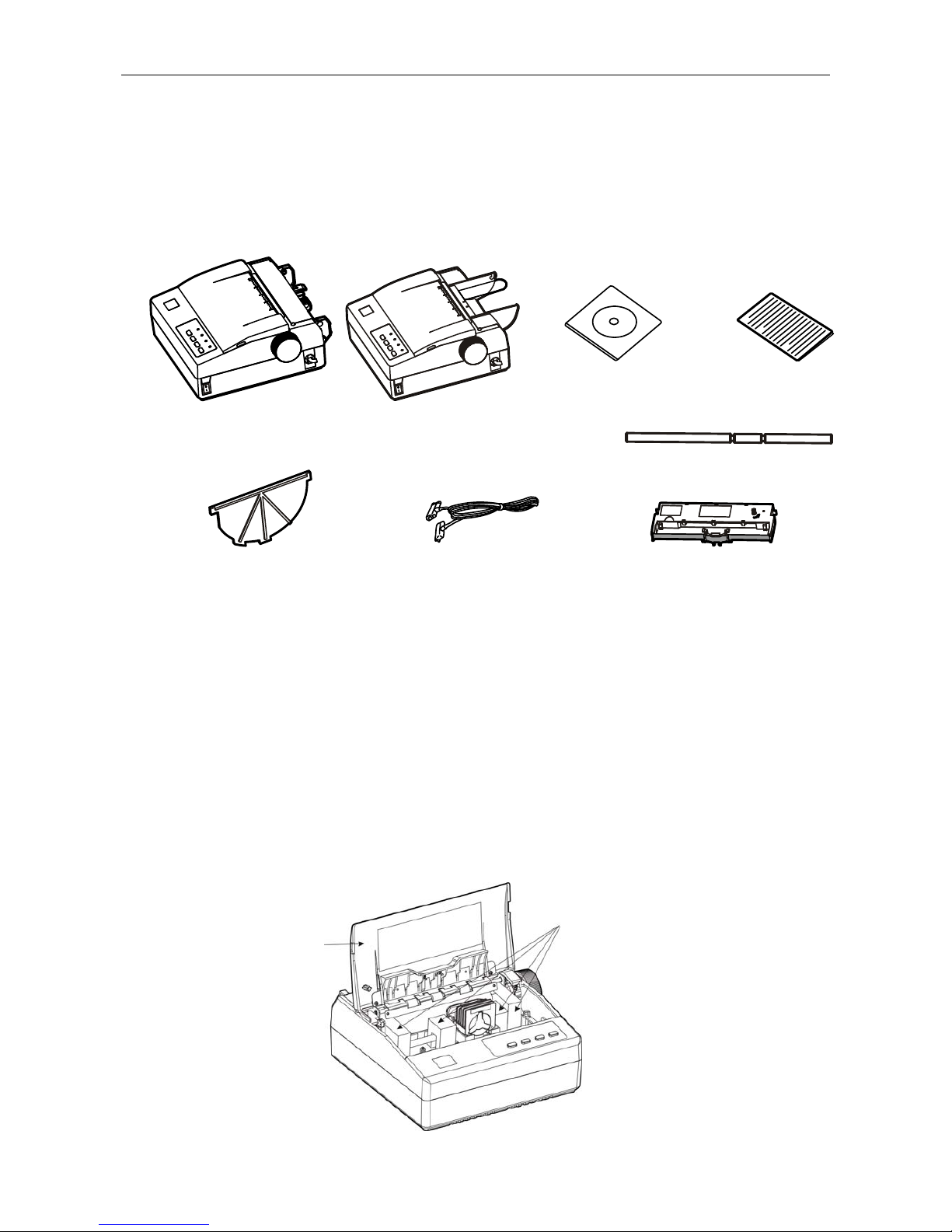
1.1 Unpacking
Check each item against the following packing list, if any of these items are missing, please
contact your local dealer.
★ Interface cable is an optional part, it is selected or canceled as client’s requirement.
Note: 1. This printer contains two types, including tractor paper and roll paper.
2. You should check the items according to the packing list and they are subject to
change without additional notice.
3. Roll paper shaft and plastic pa rtition board are special for DP100F/FS/FU/FUE (Roll
paper model).
1.2 Unpacking the Protective Materials
1. Open the packing box, take the printer out, then lift the top cover up and remove the
protective materials as follows (As shown in Figure1-2).
2. Please retain all the original packing materials in a safe place so as to transport the printer
expediently in the future.
Figure1-2 Unpacking the protective materials
Top cover
Protective materials
Figure1-1 Packing List
Parallel interface cable
(Parallel interface model)
Ribbon cartridge (JMR116)
Plastic Partition Board
(Roll paper model)
Printer
(Tractor paper model or roll paper model)
Roll paper shaft
(Roll paper model)
Driver CD
(Including User's Manual
and Windows Driver)
Facility User's Guide
DP100 User’s Manual
- 2 -
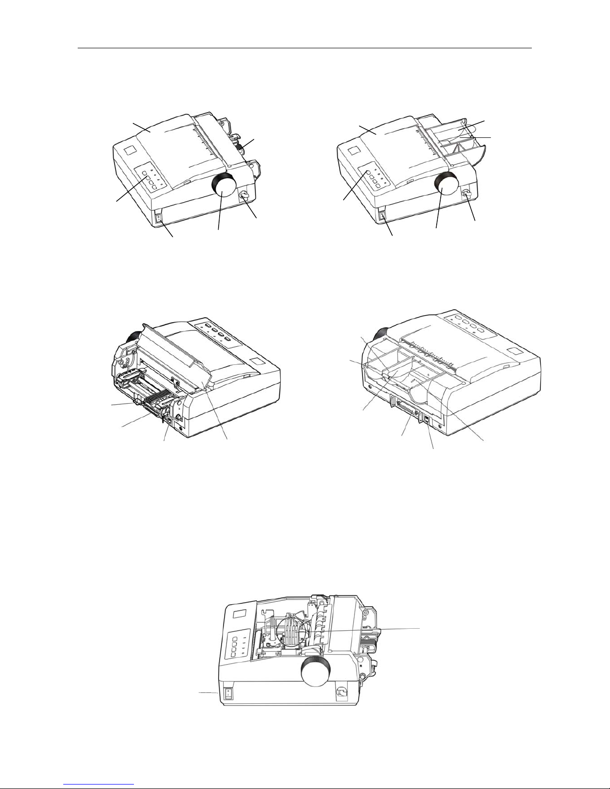
1.3 Identifying Main Parts of the Printer
★According to specific interface standards
1.4 Installing the Ribbon Cartridge
1. Make sure the printer is turned off and disconnect the power cord.
2. Uninstalling the printer’s top cover, and move the print head to the center carefully by hand
(As shown in Figure1-5).
Figure 1-3 Main parts of printer (foreside)
Fi
g
ure 1-5 Move the print head to the center
DP100/S/U/UE
Control panel
Paper feed knob
Power switch
Tractor
Power cord
Top cover
DP100F/FS/FU/FUE
Control panel
Power switch
Pa
p
er feed knob
Power cord
Paper ladle
Paper guide film
Top cover
Figure1-4 Main parts of printer (backside)
DP100/S/U/UE
Tractor
Data interface
Back cover
Cash drawer connector
DP100F/FS/FU/FUE
Plastic partition board
Pa
p
er ladle
Data interface
Paper guide film
Cash drawer connector
Roll paper shaft
Print head
Power switch
DP100 User’s Manual
- 3 -
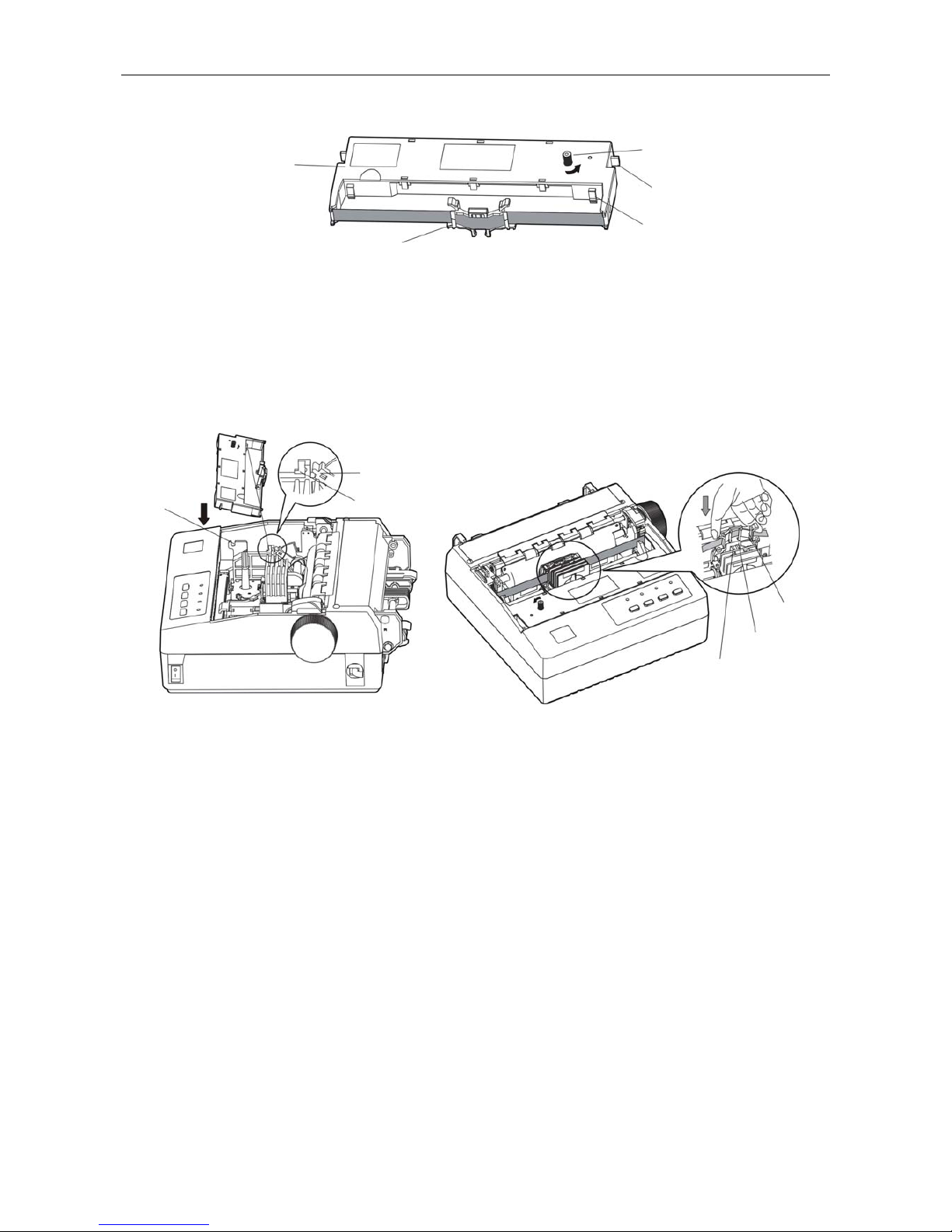
3. Hold the ribbon cartridge with the ribbon knob facing upwards and turn the ribbon knob in the
direction shown by the arrow to take up any slack in the ribbon.
4. Hold the ribbon cartridge with the ribbon knob facing upwards. (As Figure1-7 shown) Before
installing the ribbon cartridge, adjust the gap adjust lever to the appropriate position. First
push the upper locked arm into the corresponding spring hook, insert the positioning tab onto
the corresponding positioning slot, press it lightly until it clicks into place, then insert the
ribbon nip and ribbon core onto the place between the print head and the ribbon guide slice.
(At the same time, turn the ribbon knob in the direction shown by the arrow on the ribbon
cartridge to tighten the ribbon). Last, adjust the gap adjust lever according to the paper you
used. (See the details in user’s manual chapter 3.)
5. If the ribbon between the print head and platen is crinkled or twisted, it should be adjusted in
time. Turn the ribbon knob in the direction shown by the arrow on the ribbon cartridge to
tighten the ribbon.
6. Move the print head back and forth a few times to ensure the print head moves smoothly.
7. Install the top cover (As shown in Figure 1-8)
Note: 1. When print becomes faint, please replace a new ribbon cassette. Or else, it may
affect the print quality and damage the print head.
2. Make sure that the power switch has been cut off when replacing the ribbon
cartridge. Move the print head to the center carefully by hand, and then hold both
sides of the old ribbon cartridge to lift it out. And then install a new one as the
above steps.
3. Please use the Jolimark JMR116 ribbon cartridge, our company will not guarantee
to keep the printer in good repair, when it is damaged by unauthorized ribbon
cartridge.
Fi
g
ure 1-7 Installingthe ribbon cartridge
Ribbon knob
Ribbon cartridge
(JMR116)
Positioning tab
Locked arm
Ribbon nip
Print head
Ribbon nip
Ribbon guide slice
Gap adjust lever
Spring hook
Positioning slot
Figure 1-6 Ribbon cartrid
g
e

DP100 User’s Manual
- 4 -
1.5 Installing and Uninstalling the Top Cover
1.5.1 Installing the Top Cover
To have the positioning pins locked into the holes of the printer, then close the top cover. To
take its edges inosculate the printer upper cover. (As shown in Figure 1-8)
1.5.2 Uninstalling the Top Cover
Hold the convexity of top cover on both sides of the top cover, open the top cover, and then lift
it out vertically.
1.6 Connecting the Computer or Other Equipment
DP100 is equipped with one data interface (parallel interface, serial interface, USB interface or
USB & Ethernet interface) and one cash drawer interface. (According to specific interface
standards) Please contact your dealer to change the interface with payment if needed. Make
sure that you have selected the proper cable before connecting.
Note: You must make sure the printer is turned off before connecting the cash drawer
cable, parallel interface cable or serial interface cable. Only after fixing the
interface cable can you turn on the printer, or else, it will damage the printer.
1.6.1 Connecting the Cash Drawer Cable
Make sure the printer is turned off. Plug the cash drawer cable into the cash drawer
connector and the other end is connected to the cash drawer (As shown in Figure 1-9).
Note:You must use the cash drawer meets electric characteristics requirements, or else,
Figure 1-9 Connecting the cash drawer cable
Cash drawer cable
Cash drawer interface
Top cover
Positioning pin
Figure 1-8 Installing the top cover
DP100 User’s Manual
- 5 -
printer gets damaged for this reason that cannot be kept in repair service.
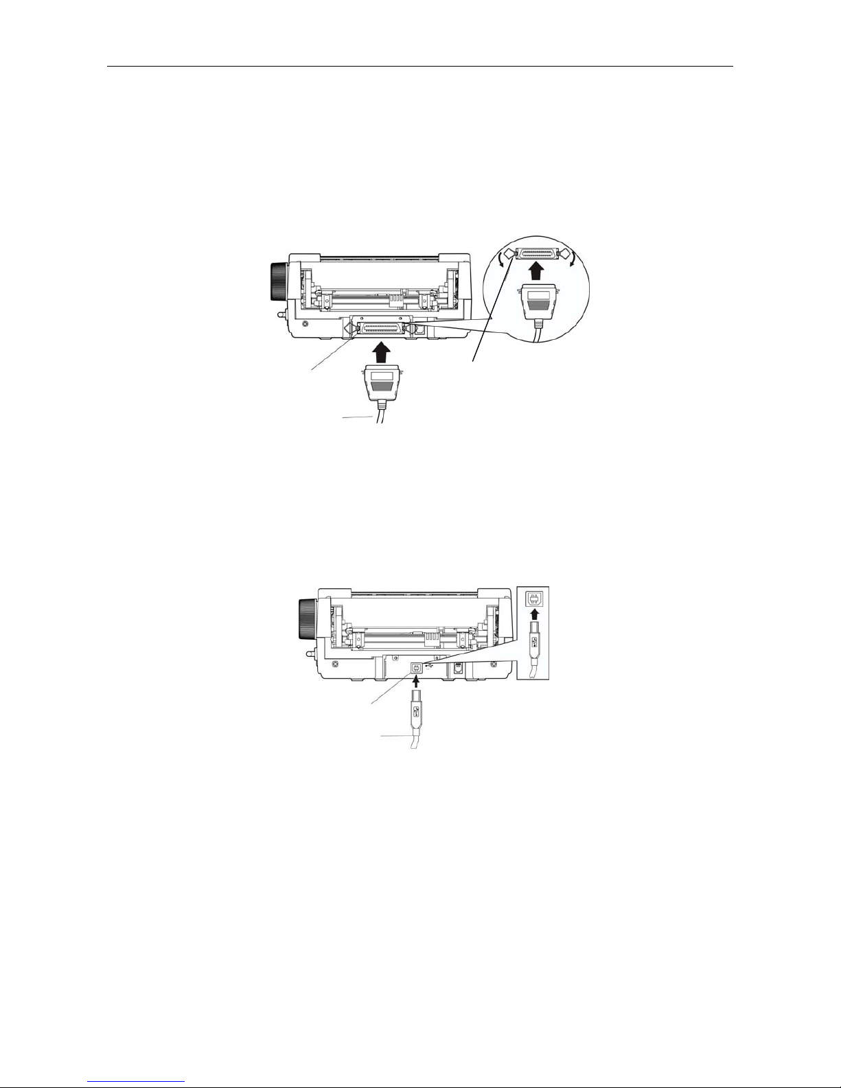
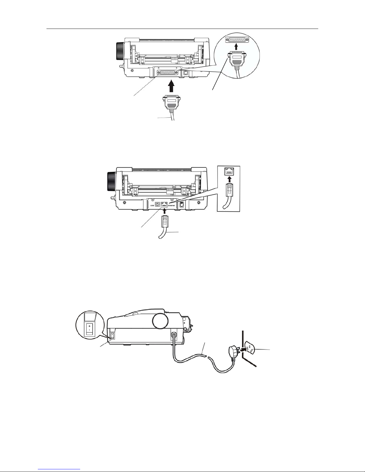
1.6.2 Connecting the Parallel Interface Cable
1. Make sure that the computer and the printer are both turned off, connect the parallel interface
cable to the connector on the rear side of the printer, squeeze the wire chips together until
they are locked into place on both sides of the connector. (As shown in Figure 1-10)
2. Connect the other end of the cable to the host computer’s parallel interface. Tighten the
screws on both sides of the printer.
1.6.3 Connecting the USB Interface Cable
1. Plug the A end of USB interface (flat type) into the computer’s USB interface connector.
2. Plug the B end of USB interface (square type) into the printer’s USB interface connector.
Note:Please don’t impact the plug after connecting to the USB cable.
1.6.4 Connecting the Serial Interface Cable
1. Make sure that the computer and the printer are both turned off, connect the serial interface
cable to the serial interface and tighten the screws (As shown in Figure 1-12)
2. Connect the other end of the cable to the host computer’s serial interface and tighten the
screws.
Fi
g
ure1-10 Connecting the parallel cable
USB interface
USB cable
Figure 1-11 Connecting the USB cable
Parallel interface
Parallel cable
Wire clips
DP100 User’s Manual
- 6 -
1.6.5 Connecting the Ethernet Interface Cable
Plug the crystal end of the Ethernet cable (RJ-45) into the printer’s Ethernet interface, plug the
other end of the Ethernet cable to the LAN. (As shown in Figure1-13)
Note: Please refer to User’s Manual for details about the Ethernet interface network
settings.
1.7 Connecting the Power Source
1. Make sure the power switch is on the OFF position (O mark on the power switch).
2. Make sure the voltage required by the printer matches that of your electrical outlet.
3. Plug the power cord into a properly grounded electrical outlet.
Warning: 1. If the voltage cannot match, please contact your dealer for assistance, do not
plug in the power cord.
2. Use the electrical outlet to connect the ground properly.
Figure 1-12 Connecting the serial cable
Figure 1-14 Connecting the power source
Serial interface
Serial cable
Screws
Power switch
Electrical outlet
Power cord
Ethernet cable
Ethernet interface
Figure 1-13 Connecting the Ethernet cable

DP100 User’s Manual
- 7 -
1.8 Installing the Driver
Install the driver after connecting the computer, insert the driver disk to the computer, and then
follow the steps below.
Auto-install way:
Double click the “setup.exe” file in the driver disk, and then follow the indications to finish
installing.
Note: Automatic setup just runs in Windows 2000 operation system or above.
Hand operated installing way
Note: The hand operated installing ways of serial cable driver and parallel cable driver
are the same.
The installing steps for Windows 2000/XP/Vista are as follows
1. Click “Start” → “Settings” → “Select Printers”.
2. Click “Add Printer”, then it will show a window of “Add Printer Wizard”, click “Next”, then
please read the select direct carefully, Such as, select “Local printer” in the “Local or
Network Printer” window, then click “next”.
3. Come out a window of “Select the Printer Port”, select a usable port. Such as, select “LPT1:
printer port”, click “Next”.
4. Come out a window of “Manufacturers/Printers”, click “Have Disk...”.
5. Come out a window of “Install From Disk”. Please according to the operating system
environment, you should select the path as follow: CD-ROM-“Driver”-“WIN
2000(XP-Vista-Win7)”, that you can find a file named: DP100.inf, click “Open”, then click
“OK”, return to the window of “Manufactures/Printers”, click “Next”.
6. Follow the direct click “Next” gradually till the installation is finished.
The installing steps for Windows 7 are as follows:
1. Click “Start” → “Devices and Printers”.
2. Click “Add a printer”, then it will show a window of “Add Printer”, click “Add a local printer”,
and then click “Next”.
3. Come out a window of “Choose a printer port”, select “Use an existing port”, Such as, select
“LPT1: Printer Port”, click “Next”.
4. Come out a window of “Manufacturers/Printers”, click “Have Disk...”.
5. Come out a window of “Install From Disk”. Please according to the operating system
environment, such as Windows 7 operating system you should select the path as follow:
CD-ROM-“Driver”-“WIN2000 (XP-Vista-Win7)”, where you can find a file named: DP100.inf,
click “Open”, then click “OK” to return to the window of “Manufacturers/Printers”, click
“Next”.
6. Follow the direct click “Next” gradually till the installation is finished.
The installing steps for windows 2000/XP/Vista/Win7 with an USB Driver:
The following steps are used Windows XP as example. There are slight differences between
different operating systems. Other installing ways are according to real practice.
1. Connect an USB cable and turn on the printer.
2. After the computer find out new hardware and finish searching, come out a window of “Add
New Hardware Wizard”, click “Next”.
3. Come out a window of “Add New Hardware Wizard”-“Windows operation”, choose “Not
Search, I want to Choose the Setup Driver (D)”, click “Next”.

DP100 User’s Manual
- 8 -
4. Come out a window of “Manufacturers/Printers”, click “Have Disk...”.
5. Come out a window of “Install From Disk”. Please according to the operating system
environment, you should select the path as follow: CD-ROM-“Driver”-“WIN2000
(XP-Vista-Win7)”, where you can find a file named: DP100.inf, click “Open”, then click
“OK” to return to the window of "Manufacturers/Printers" , click “Next”.
6. Follow the direct click “Next” gradually till the installation is finished.
The installing steps for Windows 98 are as follows:
(1)The installing steps with a parallel cable or a serial cable:
1. Click “Start” → “Settings” → “Printers”.
2. Click “Add Printer”, then it will show a window of “Add Printer Wizard”, click “Next”, then
please read the select direct carefully, Such as, select “Local printer” in the “Local or
Network Printer” window, then click “Next”.
3. Come out a window of “Click the manufacturer and model of your printer”, click “Have
Disk...”, please click “Browse”, select the path as follow: CD-ROM-“Driver”-“WIN98
(WINME)”, where you can find a file named: DP100.inf, click “Open”, and then click “OK”.
4. Come out a window of “Install From Disk”, click “OK”, return to a window of “Add Printer”,
then click “Next”.
5. Come out a window of “Printer port”, select “Available ports”, such as, select “LPT1: Printer
Port”, click “Next”, and then show the printer’s name. If the system is not installed by other
printer driver process,the printer is treated as default printer by the application process of
Window98 environment, click “Next”. Otherwise according to prompt, choose the printer is
default: “Yes”, click “Next”, choose “Yes-(recommended)”, click “Finish”. Come out a
window of “Printer test page completed”, click “Yes”.
6. The printer driver process is installed successfully.
(2)The installing steps with an USB cable:
Note: 1. As the system of Windows 98/ME doesn’t have integrated USB driver control,
please install USB driver before using USB interface printing. Then install USB
printer driver.
2. If it has installed the USB driver, please install the USB printer driver directly as
the following steps.
The installing steps of USB driver:
1. Connect an USB cable and turn on the printer.
2. After the computer find out new hardware and finish searching, come out a window of
“Add New Hardware Wizard”, click “Next”.
3. Come out a window of “Add New Hardware Wizard”-“Windows operation”, choose” Search
the best driver for the device (recommended)”, click “Next”.
4. Come out a window of “Search for new drivers”, check “Specify a location”, click “Browse”,
select the path as follows: CD-ROM-“Driver”-“【WIN98 (WINME) \ USB driver】”, then click
“OK”.
5. Return to a window of “Search for new drivers”, click “Next”; Come out a window of
“Windows driver file search for the device:”, click “Next”.
6. After the system finishes installing the file automatically, come out a window of “USB print
supported”, click “Finish”.
7. The printer USB driver process is installed successfully.
The installing steps of USB printer driver:
1. Click “Start” → “Settings” → “Printers”.
DP100 User’s Manual
- 9 -
2. Click “Add Printer”, then it will show a window of “Add Printer Wizard”, click “Next”.
3. Come out a window of “Click the manufacturer and model of your printer”, click “Have
Disk...”, please click “Browse”, select the path as follow: CD-ROM-“Driver”-“WIN98
(WINME)”, where you can find a file named: DP100.inf, click “Open”, and then click “OK”.
4. Come out a window of “Install From Disk”, click “OK”, return to a window of “Add Printer",
then click “Next”.
5. Come out a window of “Printer port”, select “Available ports”, select “JMUSB”, click “Next”,
and then show the printer’s name. If the system is not installed by other printer driver
process,the printer is treated as default printer by the application process of Window98
environment, click “Next”. Otherwise according to prompt, choose the printer is default:
“Yes”, click “Next” choose “Yes-(recommended)”, click “Finish”. Come out a window of
“Printer test page completed”, click “Yes”.
6. The printer driver process is installed successfully.
1.9 Network settings
Please use Jolimark network setting software NetFinder to set the IP address for Jolimark
printers, which can be found in the CD or downloaded from www.jolimark.com.
Note: The network printing function just runs in Windows2000 or above.
1.9.1 Connecting Printer
Power on the printer, connect with the Ethernet cable which has been connected to LAN, and
look into the information of Ethernet LED indicator to ensure the printer has entered into the
normal connection.
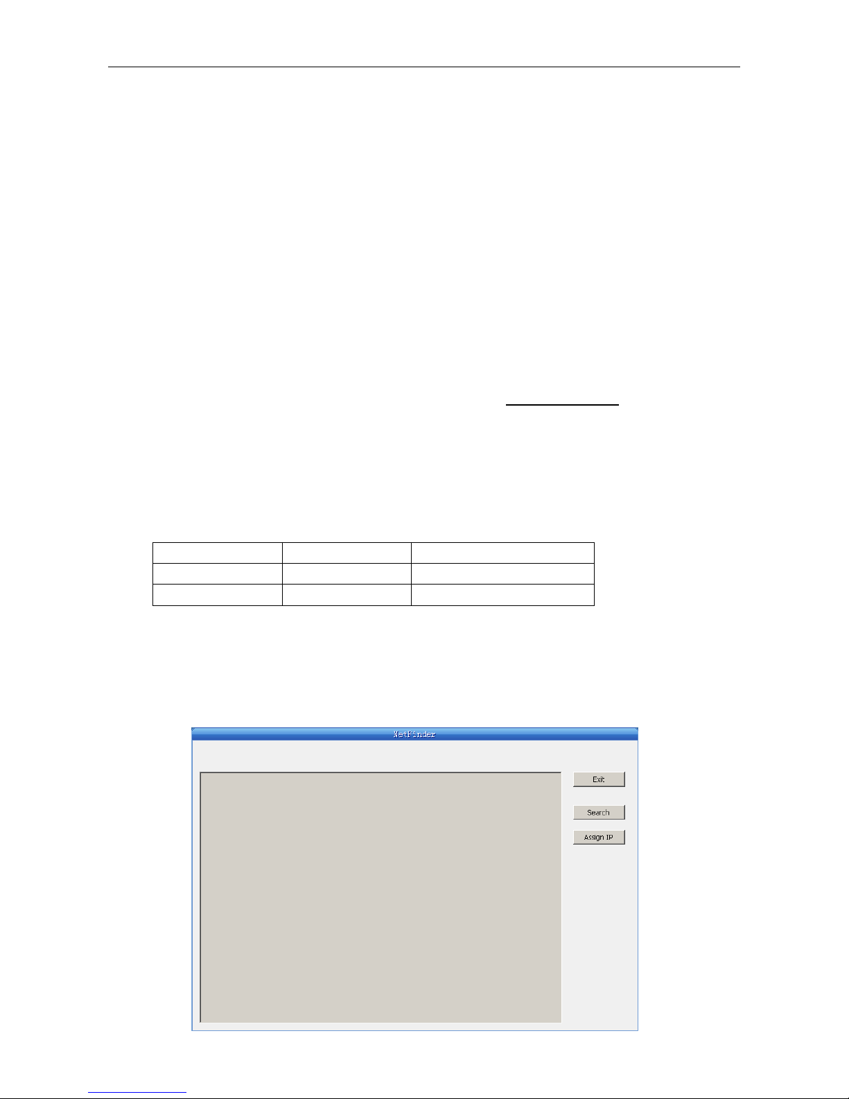
1.9.2 Setting IP Address
1. Run NetFinder Software
Double click NetFinder.exe in the PC which connects the printer in the same LAN. The
figure of the software is shown as follows:
Yellow LED Green LED Description
ON Blink Normal
OFF OFF Not connect to network
DP100 User’s Manual
- 10 -
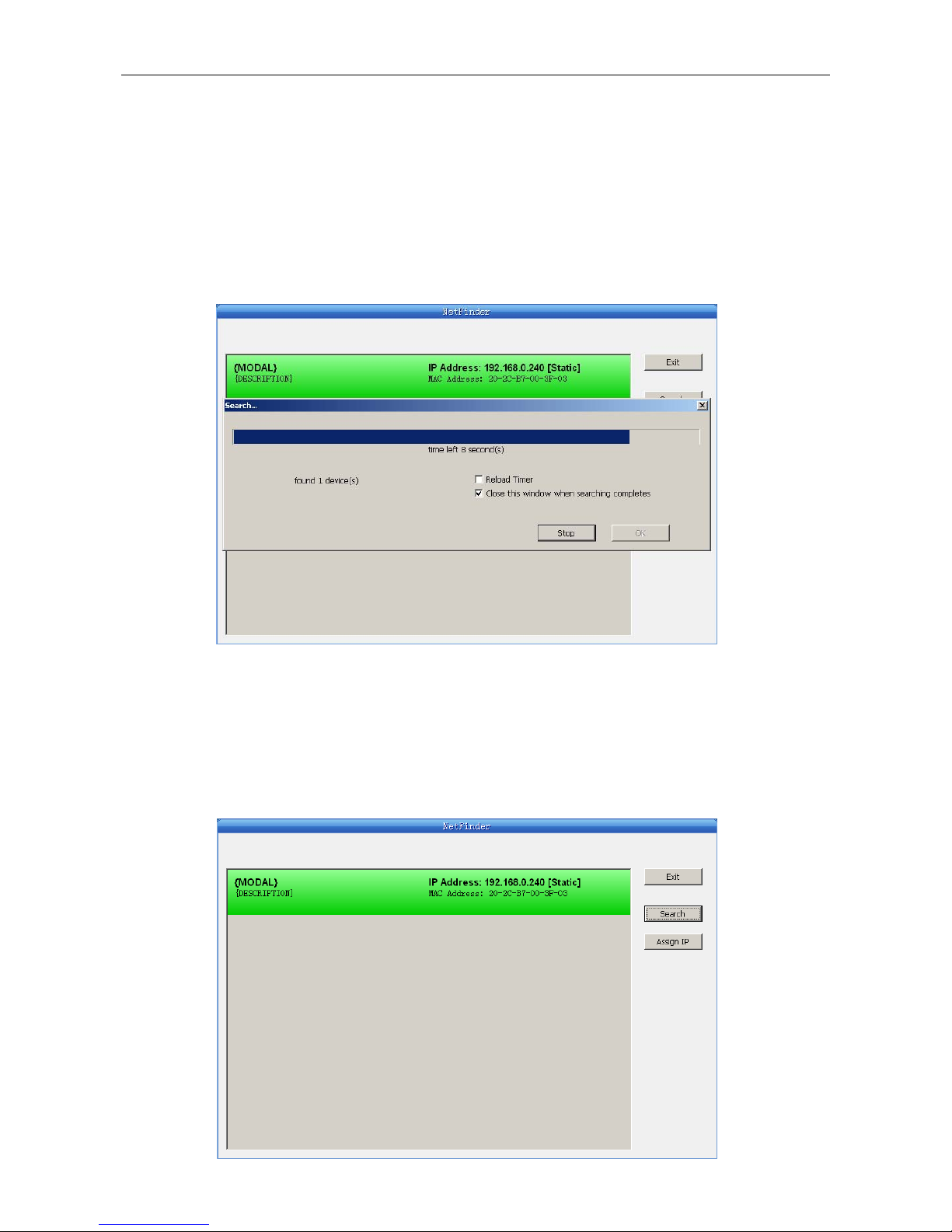
2. Search printer
Click “Search” button in the main interface, the dialog box appearing will begin searching
automatically and show appearance, listing a printer in the main interface if found. The time is
counting down in the progress bar (10s in total) and the search will finish as soon as the time
is over. When going on searching, press “search” button again.
If the printer still can not be found out when the network connection is correct and in the same
network, Please check whether the network fire wall on the PC open or not. If there is fire wall,
please close it temporarily, open again after finishing searching and setting a printer completely.
3. Setting printer’s IP address
The printer’s information is listed in the main interface, the left side of which is the model and
description and the right is the IP and MAC address. What’s more, the assign mode
(dynamic/static) is noted behind the IP address.
Button description:
Exit—Exit from the software
Search—Search printers in the same LAN
Assign IP—Modify the IP address and other settings for the specified printer.
DP100 User’s Manual
- 11 -
1) Correlative description for IP address settings
In order to search and set printer’s IP address conveniently for the first time, the factory
default setting is DHCP mode which assigns IP address dynamically. If there is no DHCP
server in the connected LAN and printer is set to DHCP mode as well, then it will use the
internal pre-set address (IP: 10.0.0.1, Subnet Mask: 255.255.255.0) automatically.
It is suggested that printer’s IP set to static in actual usage, which can cut down the time
when initializing the Ethernet interface as the printer is turned on and prevent IP conflicts
(The dynamic address used in printer may conflict with another one). The network segment
part of the IP address and Subnet Mask must be the same as those of PC connecting with a
printer. For example, the address of working PC is 192.168.0.1/255.255.255.0 (IP/Subnet
Mask),then which of printer should be set to 192.168.0.x/255.255.255.0(x=2~254 and
should avoid the IP in used. It is not restricted for NetFinder to search printers in the same
network but different segment parts (can not stride gateway). Relative glossary of IP
address may refer to corresponding information.
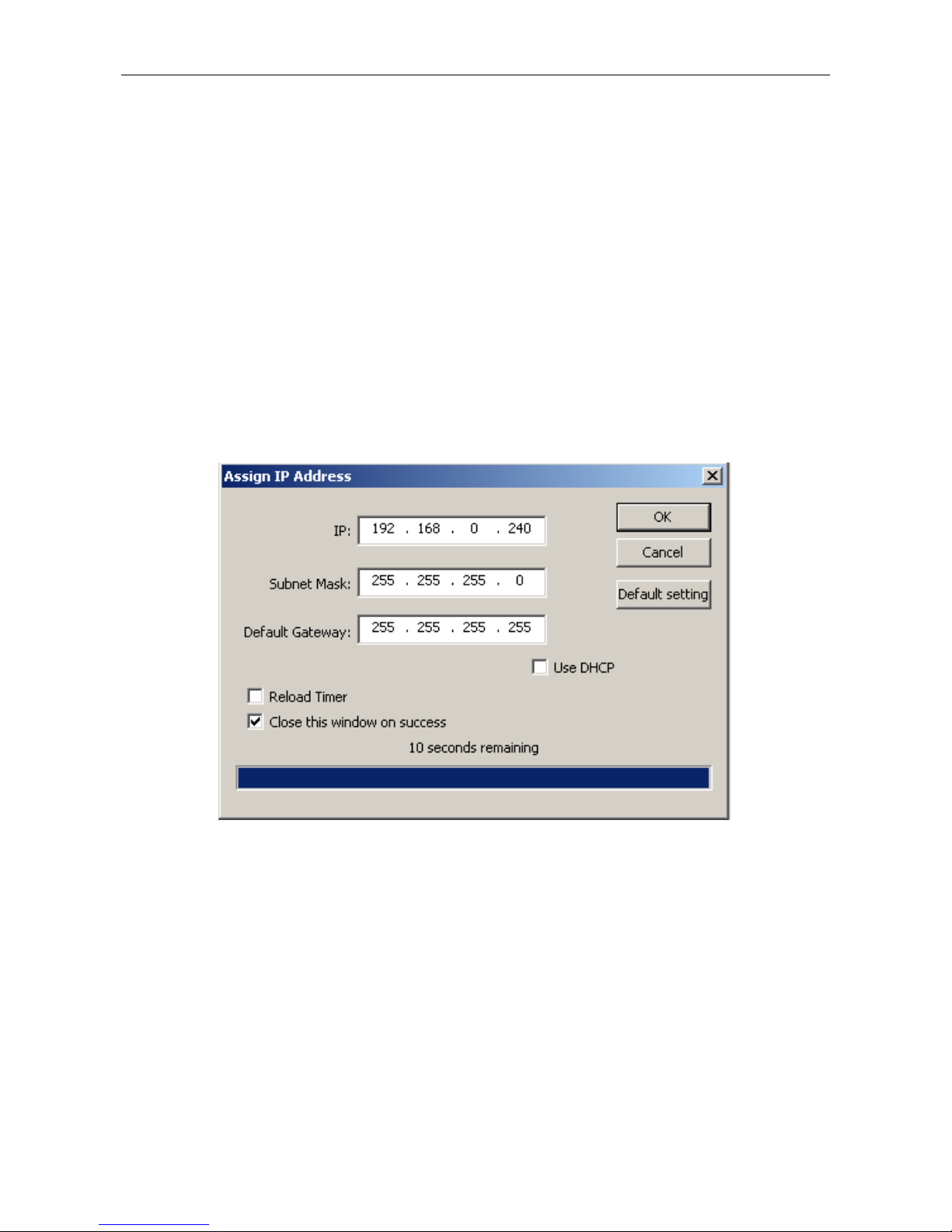
2) Setting printer’s IP address
Select the printer information to be modified (black frame appears), click “Assign IP” button.
Set the IP in the dialog box appearing.
Check the “Use DHCP” if need to assign dynamic address, the settings above will be disabled
automatically. Please make sure there is a DHCP server in the network, or the printer can not
receive an effective IP address.
When to specify static address, uncheck “Use DHCP” and fill in “IP address”, “Subnet Mask”
and “Default Gateway”. If there is no gateway in the network, fill 255.255.255.255 in the
“Default gateway”. “IP address” and “Subnet Mask” should obey the assigning rules of local
LAN (Ethernet), please enquire the administrator of networks which the printer connects to
for more details.
Click “OK” to send address setting information to the specified printer. The printer takes
response after “Close this window on success” is checked, and then this dialog is closed
automatically. Select “Reload Timer” then the software will wait for the printer’s response.
Generally, printer will take response in a circle time if network connection is correct.
Click “Cancel” if you abandon the modification.
Click “Search” in the main interface again to update printer information after modifying the
DP100 User’s Manual
- 12 -
printer’s IP address.
3) Report printer’s IP address
Report the printer’s IP address, which will be used in the section “Newly-install printer
network driver” or “Upgrade-install printer network driver (setting driver’s network port)”.
1.9.3 Installing Printer Network Driver
The ways of installing network driver are divided into Newly-install way and Upgrade-install way
according to whether the PC installs the printer driver or not.
If the printer driver hasn’t been installed on the PC, adopt newly-install way whose steps are
shown in “Newly-install printer network driver”.
If the printer driver has been installed on the PC, adopt Upgrade-install way whose steps are
shown in “Upgrade-install printer network driver”.
1. Newly-install printer network driver
1) Click “Start” → “Settings” → “Select Printers”.
2) Click “Add printer”, then come out a window of “Add Printer Wizard”, click “next”. then please
read the select direct carefully. Such as, select “local or Network Printer”, then click “next”.
3) Come out a window of “Add Printer Wizard”, then please read the select direct carefully.
Such as, select “local or Network Printer”, then click “next”.
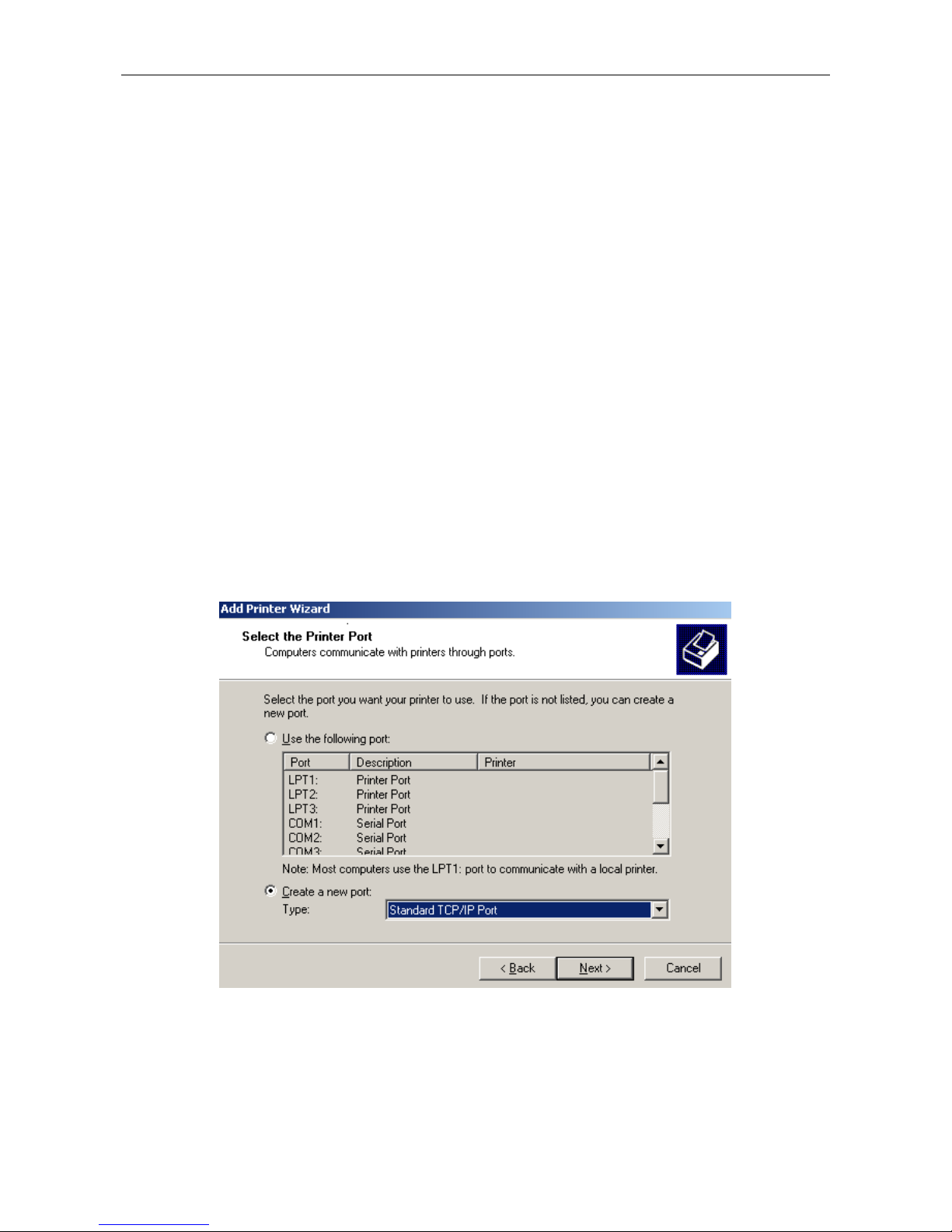
4) Come out a window of “Select the Printer port”, select a port you want your printer to use. For
example, select “Create a new port”, select “Standard TCP/IP Port” in the port, click “next”.
5) Come out a window of “Add standard TCP/IP Printer Port Wizard”, click “Next”.
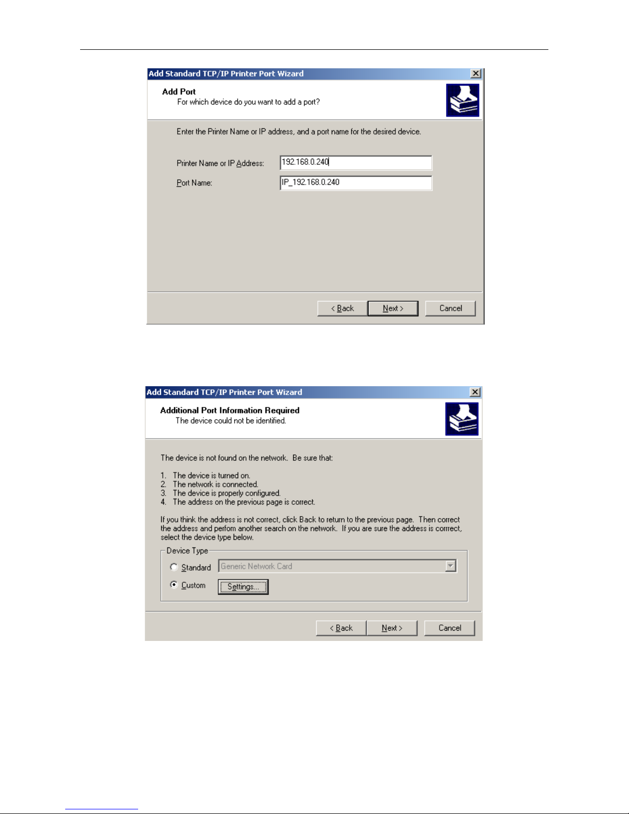
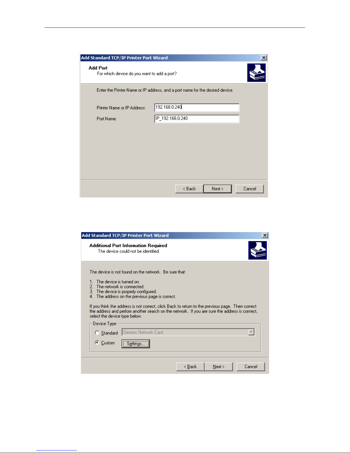
6) Come out a window of “Add Port”, enter the IP address reported by the “Setting printer’s IP
address” in the “Printer Name or IP Address” column. Take IP address “192.168.0.240” for
example. “Port Name” is created automatically after finishing filling in IP address.
DP100 User’s Manual
- 13 -
7) Come out a window of “Additional Port Information Required”, select “Custom” in the “Device
Type”, and then click “Settings”.
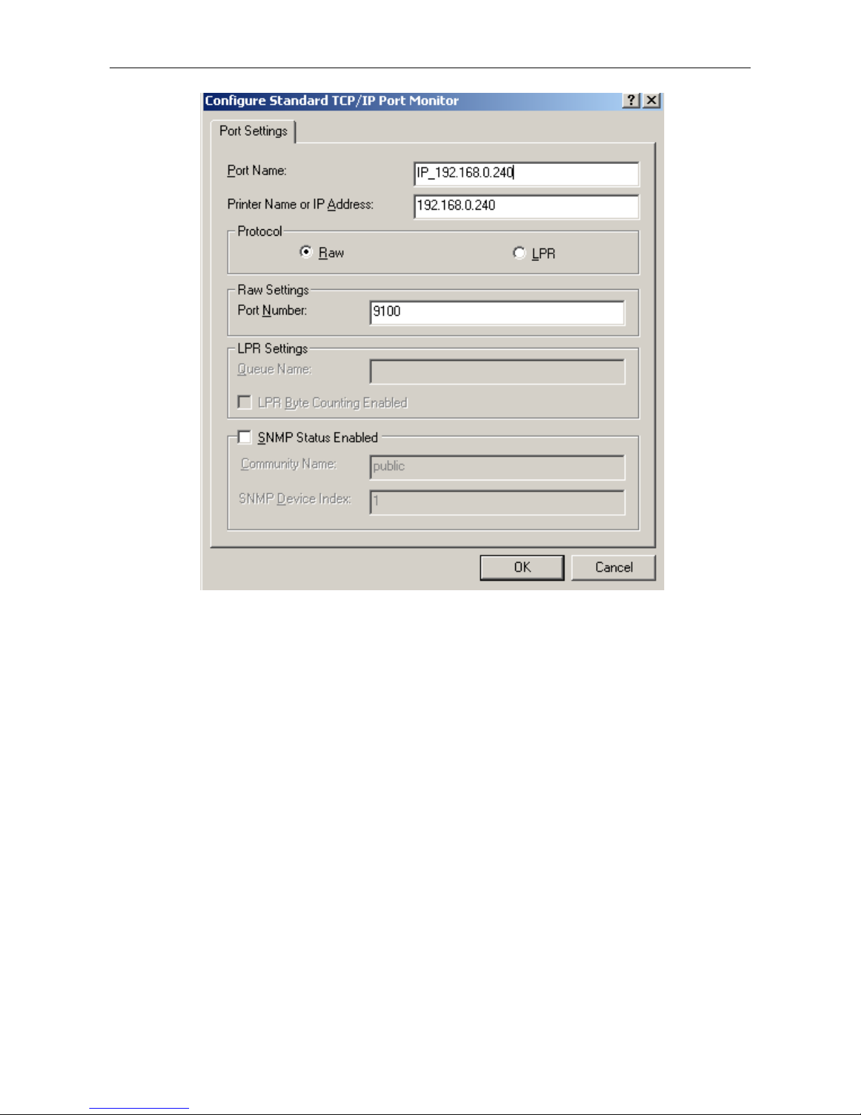
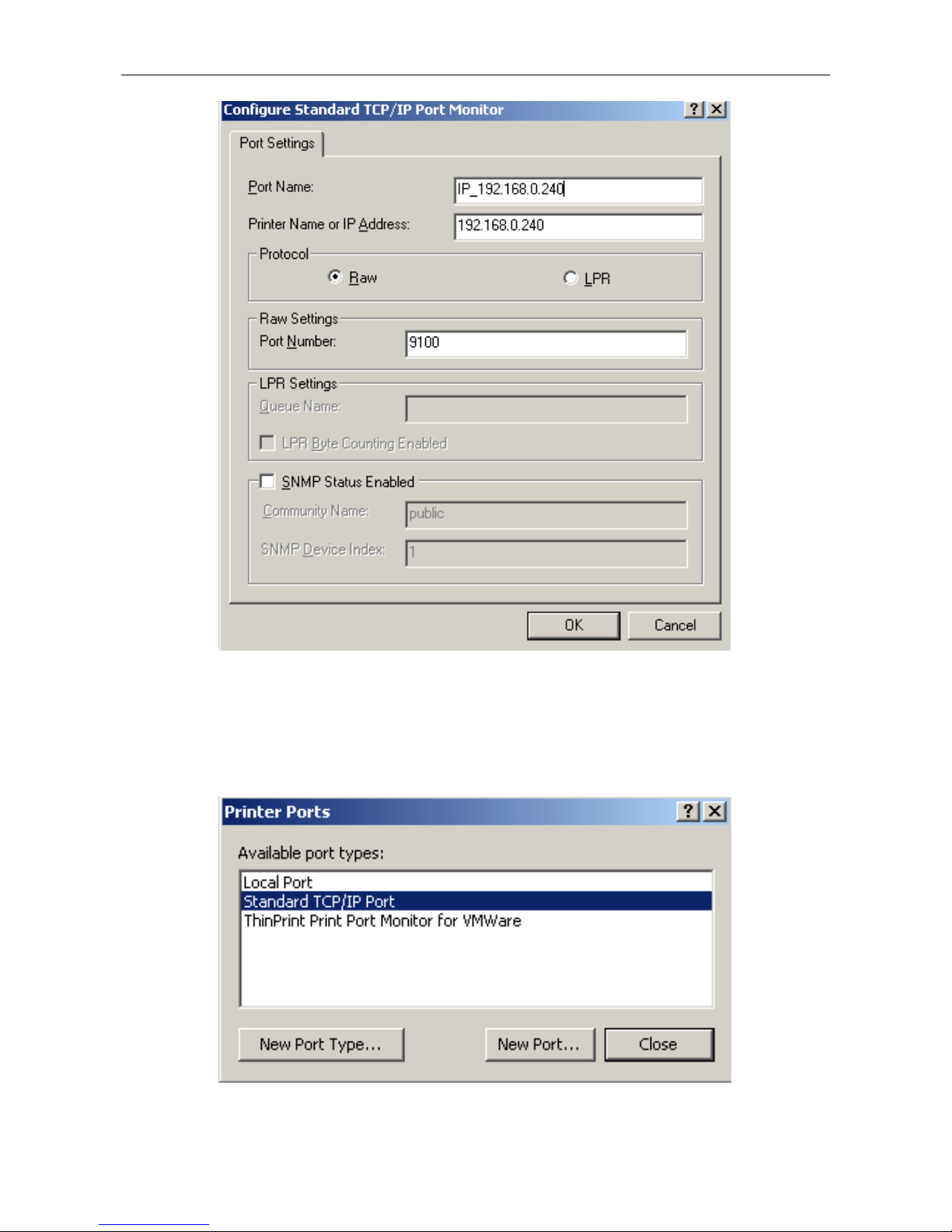
8) Come out a window of “Port Settings”. Affirm that “Port name” and “Printer name or IP
address” are correct, “Protocol” is “RAW” and “Port Number” is “9100”, click “OK”.
DP100 User’s Manual
- 14 -
9) Return to “Additional Port Information Required”, click “Next”.
10) Come out a window of “Completing the Add Standard TCP/IP Printer Port Wizard”, click
“Finish”.
11) In the selection of “Manufacturers/Printers”, click “Have Disk”, and then click “Next”.
12) Come out a window of “Install From Disk”. Please according to the operating system
environment, such as Windows 2000/XP/Vista/Win7 operating system you should select
the path as follows: CD-ROM-“Driver”-“WIN2000 (XP-Vista-Win7)”, that you can find a file
named: DP100.inf, click “open”, then click “OK”, then return to the window “install printer
software”, click “next”.
13) Follow the direct click “next” gradually till the installation is finish. At this time, printer
network driver is installed completely.
2. Upgrade-install printer network driver (setting driver’s network port)
If PC has installed the printer’s driver, set driver’s network port to carry out network printing.
The concrete steps are shown below:
1) Click “Start” → “Settings” → “Select Printers”.
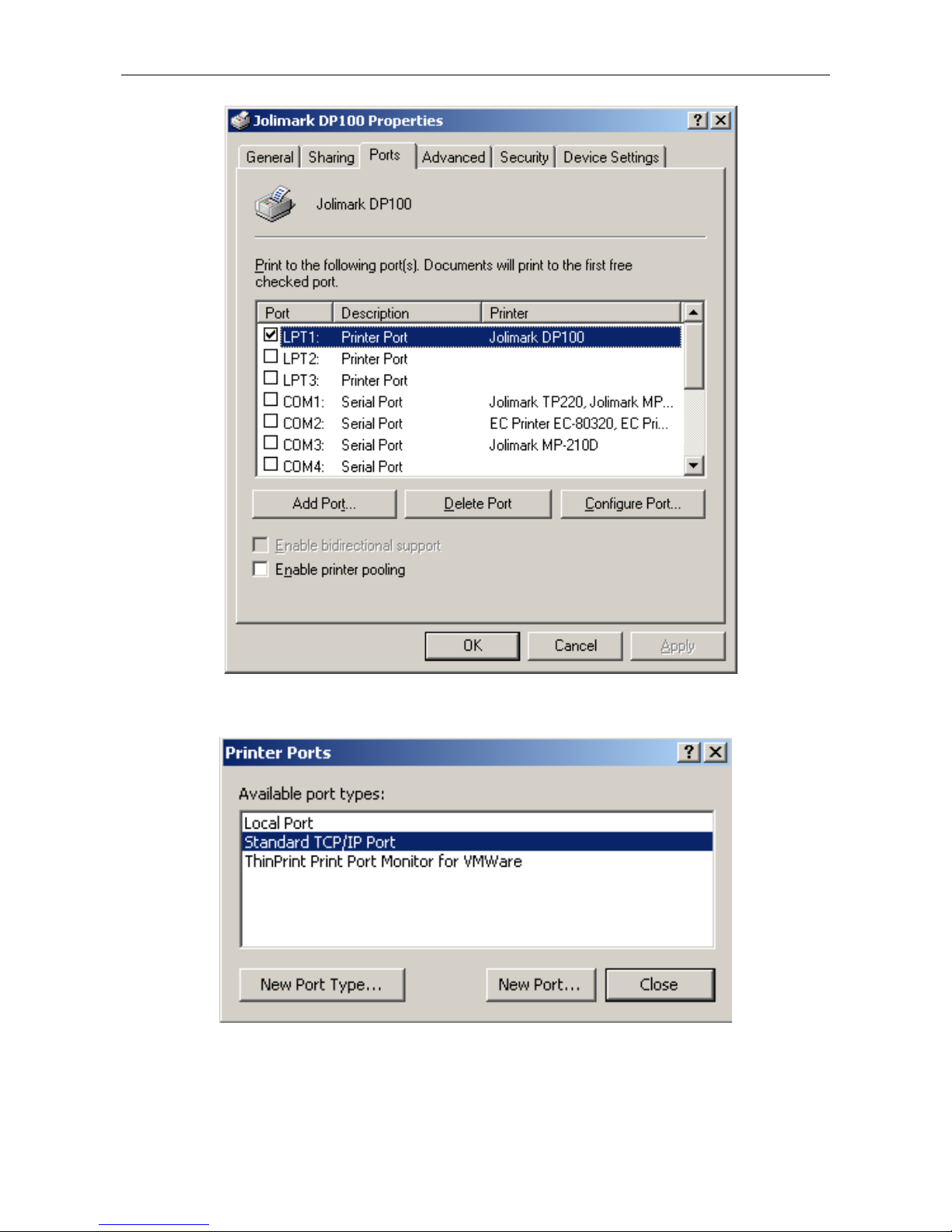
2) Right click DP100 driver, click “Properties” on the window coming out.
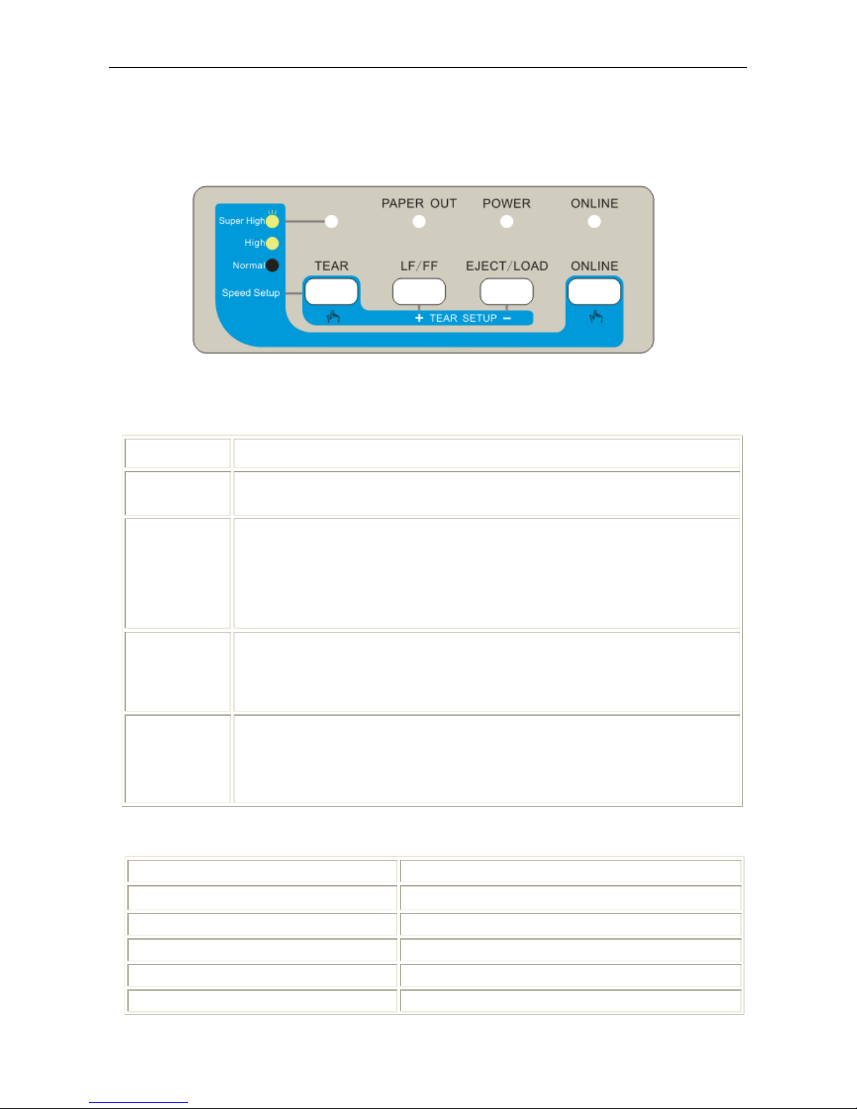
3) Come out a window of “Properties”, click “Ports” and “Add Ports”.
DP100 User’s Manual
- 15 -
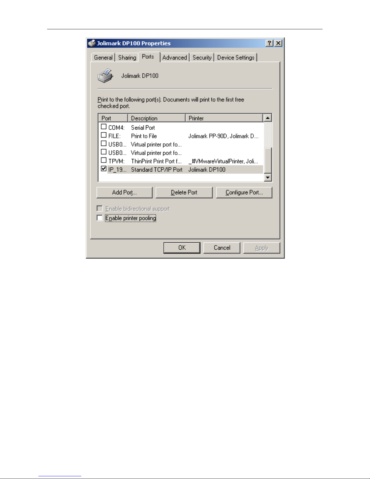
4) Come out a window of “Printer port”, select “Standard TCP/IP Port”, click “New port”.
5) Come out a window of “Add Standard TCP/IP Printer Port Wizard”, click “Next”.
6) Come out a window of “Add a port”, import the IP address reported by the “Setting
printer’s IP address” in the “Printer name or IP address” column. Take IP address
DP100 User’s Manual
- 16 -
“192.168.0.240” for example. “Port name” is created automatically after finishing filling in
IP address. Click “Next”.
7) Come out a window of “Port information”, select “Custom” in the “Equipment style”, then
click “setting”.
8) Come out a window of “Port Settings”. Affirm that “Port name” and “Printer name or IP
address” are correct, “Protocol” is “RAW” and “Port Number” is “9100”, click “OK”.
DP100 User’s Manual
- 17 -
9) Return to “Additional Port Information Required”, click “Next”.
10) Come out a window of “Completing the Add Standard TCP/IP Printer Port Wizard”, click
“Finish”.
11) Return to “Printer Ports”, click “Close”.
12) Return to “Properties”, make sure the network port is selected, click “Apply”, and then
click “Close”. Thus, printer’s network port setting is finished.
DP100 User’s Manual
- 18 -
DP100 User’s Manual
- 19 -
Chapter 2 Control Panel
2.1 Control Panel
The control panel consists of four keys and four LEDs as shown in Figure 2-1.
2.1.1 Function Keys
You can use the four keys on the control panel to operate your printer.
Key
Description
ON LINE
Press the ONLINE key, the printer is switched between ONLINE and
OFFLINE mode.
EJECT/LOAD
Press the EJECT/LOAD key when the printer is paper out, then the paper will
be fed, and it will be fed to the print position when the printer detects the
paper. In the offline mode, if the printer is paper in, press the EJECT/LOAD
key, the paper will be reversely fed (stop until exceed the setting length). In
the online mode, hold the key down for about 3 seconds; the printer will enter
the setup menu system.
LF/FF
In the offline mode, press the LF/FF key to feed the paper line by line.
Alternatively, hold the key down for about 1 second; the printer will feed the
paper one page. In the online mode, hold the key down for about 3 seconds,
the printer will enter the alignment adjust mode.
TEAR
In the online mode, press the TEAR key to advance the paper to the tear-off
position. And if you press the TEAR key again or the printer receives a new
command, the paper (the top-of-form position of the next page) will be
reversely fed to the print position. In the online mode, hold the key down for 5
seconds, the printer will be initialized (Menu settings and print speed).
2.1.2 Shortcut Keys
Keys Function
TEAR + Power Switch Long-time-printing test
LF/FF + Power Switch print-pins test
LOAD/EJECT + Power Switch Chinese self-test
ONLINE + Power Switch ASCII self-test
ONLINE + LF/FF + Power Switch H print mode
Figure 2-1 control panel

DP100 User’s Manual
- 20 -
LF/FF + TEAR + Power Switch Enter Hex Dump mode
LOAD/EJECT+ LF/FF + Power Switch Print the current printer setting
In the online mode, hold down the LOAD/EJECT key, the printer will enter the current printer
setting mode, the functions of the keys are described as follows:
Key Function
LOAD/EJECT Select the setting of the menu.
LF/FF Confirm the option
ONLINE
Press and it will return to the above menu. Pressing and holding on and it
will return to the main menu.
In the online mode, hold down the LF/FF key, the printer will enter the alignment adjust mode.
Key Function
LF/FF Increase left offset
LOAD/EJECT Increase right offset
ONLINE Print the result you just adjust
TEAR Switch the adjustment among DP, high-speed and LQ.
In the online mode, press the following keys to adjust the top of form setting.
Keys Function
ONLINE+LF/FF Increase the top of form
ONLINE+ LOAD/EJECT Decrease the top of form
In the online mode, press the following keys to adjust the tear-off position setting.
Keys Function
TEAR+LF/FF Move upwards (Tear-off position)
TEAR+ LOAD/EJECT Move downwards (Tear-off position)
In the online mode, press the following keys to adjust the print speed.
Keys Function
ONLINE + TEAR Adjust the print speed among normal speed, high speed and super high
speed
2.1.3 Indicator LED
Each indicator LED function is shown as follows:

DP100 User’s Manual
- 21 -
Indicator LED Function
ONLINE
ON:ONLINE mode; OFF: OFFLINE mode
PA PER OUT
ON: paper out; OFF: paper in
SPEED
OFF: normal speed; ON: high speed; BLINK: super high speed
POWER
ON: the printer is turned on; OFF: the printer is turned off
When the printer has something wrong, the printer buzzer sounds with “beep…beep”, and the
alarm display as follows:
Error LED
Print head overheated PAPER OUT LED is on and ONLINE LED blinks
Home position error PAPER OUT LED and ONLINE LED blinks alternately
Paper out ONLINE LED is off and PAPER OUT LED blinks.
2.1.4 Set the Print Speed, the Top of Form and the Tear-off Position
1. Set the Print Speed
Power on and with the printer online, hold down the ONLINE key, then press the TE AR key
to change the print speed: normal speed, high speed and super high speed, the state of the
speed LED is described as follows:
Normal speed: off (Speed LED)
High speed: on (Speed LED)
Super high speed: blinks (Speed LED)
2. Set the Top of Form
The top of form setting determines the margin between the top of paper and the first printed
line (the top margin). Turn on the printer, to have the paper back to the paper wharf, then
press the LOAD/EJECT key to feed the paper, next press the ONLINE + LF/FF keys to
increase the top of form or the ONLINE + LOAD/EJECT keys to decrease it. When the top
of form reaches the default setting value, the printer will sound one beep. Based on the
default value of the top of form, the maximum setting (tractor paper type) is up to 27mm and
down to 4.2mm. The maximum setting (roll paper type) is up to 12.3mm and down to 19mm.
3. Set the Tear-off Position
Turn on the printer, to have the paper back to the paper wharf, then press the LOAD/EJECT
key to feed paper, next press the TEAR key to feed the bottom of the current page to the
tear-off position. Press the TEAR+ LF/FF keys to increase the tear-off position or the TEAR
+ LOAD/EJECT keys to decrease it. When the tear-off position reaches the default setting
value, the printer will sound one beep. Based on the default tear-off position, the maximum
setting of the tear-off position is up to 4.2mm and down to 4.2mm.
2.2 To Print the Current Setting Report
You can use the information in the current setting report to decide which setting you want to
change.
To print the current setting report:
1. Turn the printer off.
2. Install tractor paper in the tractor correctly. (The width of tractor paper is at less 136mm)
3. Hold down both the LOAD/EJECT and LF/FF key at the same time. Then turn on the printer.

DP100 User’s Manual
- 22 -
The printer automatically loads paper and prints the current setting report as shown in
Figure 2-2.
LANGUAGE
ENGLISH
CHINESE
EMULATION
ESC/PK2
ESC/POS STAR 320
CHAR. MODE
ASCII
CHINESE
FONT
ROMAN
SANS SER COURIER
PRESTIGE SCRIPT OCR-B
OCR-A
EN PITCH
10 CPI
12 CPI 15 CPI
PROPORTIONAL
CN PITCH
6.7 CPI
7.5 CPI
INTL CHAR SET
U.S.A
FRANCE GERMANY
U.K. DENMARK1 SWEDEN
ITALY SPAIN 1 JAPAN
NORWAY DENMARK2 SPAIN 2
LATIN AM KOREA LEGAL
CHARACTER SET
ITALICS
GRAPHICS
CODE PAGE
U.S.A.
MULTL PORTUGAL
CANADA NORWAY EAST EURO
CYRILLIC
RUSSIAN
HUNGARY
KAMENICKY
TURKEY
ICELAND
BULGARIA
MAZOVIA
GRK 437
GRK 851
GRK8859-7
GRK 1253
ARAB NL S
ARAB EX T
WIN LAT1
WIN LAT2
ISO LTN1
ISO LTN2
TUR8859-9
ISO LTN9
KBL
LATIN 7
LINE SPACING
6 LPI
8 LPI
FORM LENGTH
3.5 INCH 5 INCH 7 INCH
LETTER
A4 12 INCH
14 INCH
PAGE SKIP
OFF
ON
TEXT DIR
BI-DIR
UNI-DIR
Jolimark DP100
Current Setting Report
Version X.XX XXX XXXX-XX-XX
SN: XXXXXXXXXXXXXXXXXXX
DHCP: XX IP: XXX.XXX.XXX
Subnet Mask: XXX.XXX.XXX.XXX
Gateway: XXX.XXX.XXX.XXX
MAC: XX-XX-XX-XX-XX-XX

DP100 User’s Manual
- 23 -
GRAPHIC DIR
BI-DIR
UNI-DIR
QUIET MODE
OFF
ON
AUTO LF
OFF
ON
FF TO TEAR
OFF
ON
FF BY CONTENT
OFF
ON
LOADING
PUSH KEY 0.5 SEC.
1.0 SEC.
2.0 SEC.
IMPACT MODE
OFF
ON
PAPER TYPE
TRACTOR
ROLL
BLACK MARK
OFF
ON
TEAR KNIFE
OFF
ON
PIN SWITCH
OFF
ON
HEAD PIN
PIN 1
LIVE
BROKEN
PIN 2
LIVE
BROKEN
PIN 3
LIVE
BROKEN
PIN 4
LIVE
BROKEN
PIN 5
LIVE
BROKEN
PIN 6
LIVE
BROKEN
PIN 7
LIVE
BROKEN
PIN 8
LIVE
BROKEN
PIN 9
LIVE
BROKEN
PIN 10
LIVE
BROKEN
PIN 11
LIVE
BROKEN
PIN 12
LIVE
BROKEN
PIN 13
LIVE
BROKEN
PIN 14
LIVE
BROKEN
PIN 15
LIVE
BROKEN
PIN 16
LIVE
BROKEN
PIN 17
LIVE
BROKEN
PIN 18
LIVE
BROKEN
PIN 19
LIVE
BROKEN
PIN 20
LIVE
BROKEN
PIN 21
LIVE
BROKEN
PIN 22
LIVE
BROKEN
PIN 23
LIVE
BROKEN
PIN 24
LIVE
BROKEN
Note: The options whose color is printed contrarily are the current settings. If the
initialization of “Language” is “English”, saving the setting and operating the upper
steps again, and it will print the current settings in English. The way of changing the
settings is in the next section.
2.3 To Enter the Setup Menu System and Change the Settings
1. Make sure that the printer is in the online mode. The ONLINE LED is on.
Figure 2-2 Current setting report

DP100 User’s Manual
- 24 -
2. Hold down the LOAD/EJECT key for about 3 seconds.
The PAPER OUT LED and ONLINE LED blinks two times simultaneously. The printer enters
setup menu system.
Firstly, it prints out title and main menu. (As Figure2-3 shown) The default options are
underlined. The print head stop below the default option.
3. Make a selection from the menu with the keys on the control panel:
Press: To:
EJECT/LOAD
Select the menu options or setting value.
LF/FF
Enter the submenu or affirm the setting value.
Note: Newly settings are shown in FILL.
ONLINE
Go to the above menu, holding down this key will return to the main menu.
4. When you have made all of your settings (remember that you don’t have to go all the way
through the menu system), switch the printer off and then turn on again. New settings of the
menu will be stored.
2.4 Description of Options
Options Description
LANGUAGE Select the language you want, ENGLISH or CHINESE
EMULATION Select the emulation you want, ESC/PK2, ESC/POS or STAR 320 emulation
CHAR. MODE Select ASCII characters (1 byte) or Chinese characters (2 bytes)
Figure 2-3 Setup menu system
Jolimark DP100
SETUP MENU SYSTEM
Version X.XX XXX XXXX-XX-XX
SN: XXXXXXXXXXXXXXX
DHCP: XX IP: XXX.XXX.XXX
Subnet Mask: XXX.XXX.XXX.XXX
Gateway: XXX.XXX.XXX.XXX
MAC: XX-XX-XX-XX-XX-XX
Use EJECT/LOAD key to point the print head to
the desired setting.
Use LF/FF key to confirm the current setting.
Use ONLINE key to go back the previous menu
(Press and hold the ONLINE key to go back to
the main menu).
Press and hold the TEAR key to exit the setup.
Current settings are
New settings will be FILLED
SYSTEM SETUP CHARACTER
PAGE LAYOUT PRINT SETUP

DP100 User’s Manual
- 25 -
FONT
Set the font for the printer to use in the absence of any font control instructions
from your software.
EN PITCH
Set the pitch to determine the horizontal spacing of the printed ASCII
characters.
CN PITCH
Set the pitch to determine the horizontal spacing of the printed Chinese
characters.
INTL CHAR SET
Select the internal character set (Only compatible to EPSON)(U.S.A., FRANCE,
GERMANY, U.K., DENMARK1, SWEDEN, ITALY, SPAIN 1, JAPAN, NORWAY,
DENMARK2, SPAIN 2, LATIN AM, KOREA, LEGAL)
CHARACTER SET Select character set into Italic Character set or Graphic Character set.
CODE PAGE Select a code page.
LINE SPACING
Set the line spacing of the printed characters. You can set it to either 1/6 inch
(the default setting) or 1/8 inch.
FORM LENGTH
Set the length of your printer paper, for both cut sheet or tractor paper.
PAGE SKIP Select (ON) or cancel (OFF, the default) a bottom margin of one inch.
TEXT DIR
Set unidirectional or bi-directional printing for text.
GRAPHIC DIR
Set unidirectional or bi-directional printing for graphics. It is just compatible with
EPSON.
QUIET MODE
Select the printer into quiet mode.
AUTO LF
Select (ON) or cancel (OFF) the automatic advance of the paper by one line
after every carriage return command.
FF TO TEAR
Select (ON) or cancel (OFF) the automatic form feed to tear position in
continuous paper mode. When the tear off function is open, the printer receives
no printable data in a period of time after it receives form feed command, the
printer feeds the bottom of continuous paper to tear off position automatically.
FF BY CONTENT
Select (ON) or cancel (OFF) the form feed by content to tear position in
continuous paper mode. When the tear off function is open, the printer receives
no printable data in a period of time after it receives form feed command, the
printer feeds the content-end position to tear off position.
LOADING This determines the action of the printer while it detects there is paper in.
Select loading paper by pressing LF/FF key or automatic feeding after the
stated delay time (0.5sec, 1.0sec or 2.0sec).
IMPACT MODE
Enable or disable impact mode function. When you select COPY print, enable
the impact mode function and you will gain the good print effect.
PAPER TYPE Select the paper type: tractor paper or roll paper.
BLACK MARK Enable or disable the black mark function.
TEAR KNIFE Enable or disable the tear cutter.
PIN SWITCH
Enable or disable the pin switch function. After open pin switch function, the
printer will switch different print pins when printing Chinese tabs
HEAD PIN
Setting the situation of print pin. The default setting of the print pins are LIVE.
But it may be break pins during printing, users can set the corresponding pins
as “BROKEN”, and then the printer will compensate the position of broken pins
automatically.
2.5 Online-aptitude Parameter Settings
DP100 supports the function of online-aptitude parameter settings, which can be set in the PC with
the driver installed in.

DP100 User’s Manual
- 26 -
The concrete setting steps are shown as follows:
1. Make sure that the host and the printer are connected with a cable and both the host and the
printer is turned on, the printer should be online as well.
2. Click “Start” → “Settings” → “Printers”, open the window of “Printers”.
3. Right click “Jolimark DP100” in the “Printers”, select “Properties”.
4. Click “Device
Property” in the property page.
5. The setting way is corresponding with that of printer menu system. In the “Printer Settings” layout,
select the first class menu in the combo box of “Select Printer Setting Class”, select the second
menu in the “Configuration” and set the item in the current parameters list.
6. Click the button “Reset All” to reset all the parameters to be the driver’s default, but not change the
printer’s settings.
7. When setting the parameters: you can click “Set Item” to save the current settings after setting
each item, or you can also click “Set All Items” after setting all parameters. After clicking “Set All
Item” or “Set Item”, the parameter’s instruction will be sent to the printer.
8. The printer’s parameter settings are changed at once after receiving the instruction and the printer
does not need to restart.
9. After finishing settings, click “OK”, exit the “Properties” window.
2.6 Using the Self Test Functions
Maintenance Printing Test (H Print Mode)
Continuous printing of H pattern is performed by turning power on, while pressing the ONLINE
+ LF/FF keys. Pressing the ONLINE key can stop printing, and turn off the printer to exit the H
print mode.
DP100

DP100 User’s Manual
- 27 -
ASCII Test Mode
Continuous printing of ASCII pattern is performed by turning power on, while pressing the
ONLINE key. Pressing the ONLINE key can stop printing, and turn off the printer to exit H print
mode.
Chinese Self-test
Turn the power on while pressing the LOAD/EJECT key after feed the paper correctly. The
printer will print out a piece of Chinese self-test sample.
Figure 2-5 H print mode
Figure 2-6 ASCII test mode
Figure 2-7 Chinese self-test mode
Chinese self-test mode
Jolimark DP100
Version X.XX XXX XXXX-XX-XX
SN: XXXXXXXXXXXXXXX
DHCP: XX IP: XXX.XXX.XXX
Subnet Mask: XXX.XXX.XXX.XXX
Gateway: XXX.XXX.XXX.XXX
MAC: XX-XX-XX-XX-XX-XX
、 。 · ˉ ˇ ¨ 〃 々 — ~ ‖ … ‘ ’
」 『 』 〖 〗 【 】 ± × ÷ : ∧ ∨ ∑ ∏
⊙ ∫ ∮ ≡ ≌ ≈ ∽ ∝ ≠ ≮ ≯ ≤ ≥ ∞ ∵
¢ £ ‰ § № ☆ ★ ○ ● ◎ ◇ ◆ □ ■ △
ⅲ ⅳ ⅴ ⅵ ⅶ ⅷ ⅸ ⅹ ⒈ ⒉ ⒊ ⒋ ⒌ ⒍ ⒎
H PRINT MODE
Jolimark DP100
Version X.XX XXX XXXX-XX-XX
SN: XXXXXXXXXXXXXXX
DHCP: XX IP: XXX.XXX.XXX
Subnet Mask: XXX.XXX.XXX.XXX
Gateway: XXX.XXX.XXX.XXX
MAC: XX-XX-XX-XX-XX-XX
HHHHHHHHHHHHHHHHHHHHHHHHHHHHHHHHHHHHHHHHHH
HHHHHHHHHHHHHHHHHHHHHHHHHHHHHHHHHHHHHHHHHH
HHHHHHHHHHHHHHHHHHHHHHHHHHHHHHHHHHHHHHHHHH
ASCII TEST MODE
Jolimark DP100
Version X.XX XXX XXXX-XX-XX
SN: XXXXXXXXXXXXXXX
DHCP: XX IP: XXX.XXX.XXX
Subnet Mask: XXX.XXX.XXX.XXX
Gateway: XXX.XXX.XXX.XXX
MAC: XX-XX-XX-XX-XX-XX
!"#$%&'( )*+-./0123456789:;<=>?@ABCDEFG
!"#$%&'( )*+-./0123456789:;<=>?@ABCDEFGH
"#$%&'( )*+-./0123456789:;<=>?@ABCDEFGHI
#$%&'( )*+-./0123456789:;<=>?@ABCDEFGHIJ

DP100 User’s Manual
- 28 -
Hex Dump Mode
Turn the power on while pressing the LF/FF + TEAR keys, then the printer will enter Hex Dump
mode. In this mode, the data which are sent from computer will print with Hex mode.
Current Setting Printing Mode
The printer will print out a piece of current setting report is performed by turning power on, while
pressing LOAD/EJECT and LF/FF keys. The printing format is similar with that of Menu
system.
Alignment Adjust
Enter the alignment adjust mode to improve the print quality when the printer is used for a long
time.
1. Make sure the printer is paper in and turn on the printer.
2. In the online mode, press and hold on the LF/FF key for about 3 seconds, the printer prints
the degree of make columns (DMC).
3. After entering the alignment adjust mode, press EJECT/LOAD and LF/FF keys to adjust the
degree of make columns:
LOAD/EJECT Each press this key, the singular line will move right with one step (30
steps max.)
LF/FF Each press this key, the singular line will move left with one step (30
steps max.)
4. Press the ONLINE key to save the setting and the printer will print the setting which has been
set.
5. Repeat step 3 and step 4 to adjust the DMC until you are satisfied with the result.
6. Press the TEAR key to switch to another alignment adjust mode, such as DP\HIGH SPEED
and LQ, as shown in Figure 3, 4.
7. Restart the printer and exit the alignment adjust mode.
Note: Alignment adjust mode will affect the print quality, please make a thorough
consideration before adjusting it, and you must follow the instructions strictly.
DUMP MODE
0000: BD F8 C8 EB CA AE C1 F9 BD F8 D6 C6 C4 =xHKJ.Ay=Xvfd
000D: A3 CA BD BA F3 A3 AC B6 D4 B5 E7 C4 D4 #J=:S#,6T5Gdt
001A: B4 AB CA E4 C0 B4 B5 C4 CA FD BE DD A3 4+Jd@45DJ}>]#
0027: AC BD AB D2 D4 CA AE C1 F9 BD F8 D6 C6 ,=+RTJ.Ay=xVF
Figure 2-8 Hex Dump Mode

DP100 User’s Manual
- 29 -
Chapter 3 Loading Paper
DP100 can use many kinds of different specification papers. And it also has convenient install and
uninstall paper function. This chapter will introduce these functions in detail.
3.1 Paper Thickness Adjustment
Before loading roll paper or tractor paper, you have to adjust the gap adjust lever on the right
side of the printer. To feed thicker paper through the printer, you need to move the gap adjust
lever from its standard position. The lever moves the print head relative to the platen so that
there is more room for the paper.
Adjusting the gap adjust lever
To obtain good quality printing and avoid problems (paper jam etc.), adjust the gap adjust lever
as shown in the Figure 3-1. The scale number # 1 shown in Figure 3-1 identifies the standard of
paper thickness setting. This is the recommended setting for most paper. Use Table 3-1 to find
the recommended setting for other paper.
Paper Typ e Lever Position
Standard Paper
(single roll paper or single tractor paper)
1
Original +1 copy 2
Multiple
Original +3 copies 3 or 4
Reserved 5 or 6
3.2 Top of Form Adjustment Mode
The top of form setting determines the margin between the top of paper and the first printed line
(the top margin). You can set the top of form without using the paper feed knob (See section
2.1.4 for details).
Note: The top margin setting is only effective to the first page.
3.3 Loading the Tractor Paper
1. Ensure the tractor unit has been installed on the back of the printer and the printer is turned
off.
2. Lift up the back cover.
Figure 3-1 Setting the gap adjust lever
Gap adjust lever

DP100 User’s Manual
- 30 -
3. Release the tractor locking levers, adjust the tractor position, and make it closed to the paper
width.
4. Open the tractor covers and place the paper on the sprocket pins of the tractor unit, then
close the tractor cover.
5. Move the two tractors to make the paper tight, and then push down the two tractor locking
levers.
6. Close the back cover.
Figure 3-2 Lift up the back cover
Figure 3-4 Place the paper on the sprocket pins
Figure 3-3 Release the tractor locking levers
Figure 3-5 Close the tractor covers
Tractor cover
Back cover
Tractor locking lever
Tractor
Figure 3-6 Close the back cover

DP100 User’s Manual
- 31 -
7. Turn on the printer after installing the tractor paper, press LOAD/EJECT key, then it can load
tractor paper automatically. Then adjust the top of form position.
3.4 Loading the Roll Paper
1. Ensure the paper ladle has been installed on the back of printer and the printer is turned off.
2. According to the size of the roll paper you used, insert the plastic partition board into the
paper ladle. If you use the 76mm wide roll paper, please insert the plastic partition board
into the paper ladle where is marked 76mm position, and if you use the 57.5mm wide roll
paper, please insert the plastic partition board into the paper ladle where is marked 57.5mm
position, and if you use the 114mm wide roll paper, please demount the plastic partition
board and retain it.
3. Pull out the paper after turning on the printer, and push the head of the paper into the paper
guide, the paper may load into the printer automatically. Then endue the roll paper shaft,
uncover the roll paper guide film, finally, take the paper roll into the paper ladle.
(Note: The direction that the paper comes off the roll, which is shown as Figure 3-7.
Take the roll paper guide film above the roll paper to prevent the paper from
entangling into the paper guide.)
4. Finish loading paper when the black mark function isn’t selected. If the black mark function is
selected, the printer will feed paper continuously for seeking the black mark until the black
mark is found (If the black mark isn’t found for a certain distance, the printer will stop feeding
paper).
5. Finish loading paper as shown in figure 3-8.
Figure 3-8 Finish installing roll paper
Figure 3-7 Loading the Roll Paper
Roll Paper
Plastic Partition Board
76mm position
Roll Paper Shaft
Paper Feed Knob
57.5mm position
Paper Guide Film

DP100 User’s Manual
- 32 -
6. Turn the paper feed knob to adjust the Top-of-Form position.
At this time, printer has already prepared for files printing. Before loading paper, printer stays at
waiting state, and indicators on control panel will remind you of loading paper according to
“Paper-out” indicator on.

DP100 User’s Manual
- 33 -
Appendix A Maintenance and Troubleshooting
A.1 Maintenance
Clean out the waste paper or other sundries inside the printer periodically. Close the
top cover when the printer is not being used.
Periodic cleaning and cleaning tool
Periodic cleaning: every six months or 300 working hours once
Cleaning tools: dry cloth (clean the metal parts with soft cloth)
Cleaning the spare parts
Wipe soiled parts of the printer with a clean cloth.
Cleaning the paper feed platform
Please wipe off the wasted paper and clean dirt and dust.
Cleaning the carriage shaft
There is a layer of oil covered on the carriage shaft which guarantees the carriage can run
smoothly. But the oil is easy to absorb dust, please clean the dust with soft cloth first, add
proper lube (NYE180 lube of NYE company is recommended), move the print head back and
forth and make the lube scattered.
Cleaning the black mark detector
Because black mark sensor is photoelectric sensor, it needs to clean periodically.
Clean the surface of black mark sensor which under the platen every 3 months.
Note: 1. Being used under dusty circumstance, the carriage shaft may stack much dust and
affect the print quality.
2. Turn off the printer and pull out the power cord before cleaning.
3. If you have just finished using the printer, let the print head cool for a few minutes
before you clean it.
4. Don't use hard cloth and flammable solvent for cleaning.
A.2 Error LED on the Control Panel
(1) Print head overheating protection
Phenomenon: PAPER OUT LED is on, ONLINE LED blinks, and the print head is moving, but
Black mark sensor
Paper path
Carriage frame
Carriage shaft
Figure A-1 Cleaning printer

DP100 User’s Manual
- 34 -
not printing.
Reason: The temperature of the print head is too high, so it enters into the protection state.
Solution: Wait patiently, and the printer will recover automatically after the print head is cool.
(2) Fault check of the restoration sensor
Phenomenon: PAPER OUT LED and ONLINE LED blink alternately.
Reason: Fault check of restoration sensor.
Solution: Turn off and then turn on the printer.
(3) Printer is paper out
Phenomenon: ONLINE LED is off and PAPER OUT LED is on.
Reason: Paper out.
Solution: Load paper again.
A.3 Troubleshooting
WARNING: Never attempt to repair the printer by yourself.
z Power supply
Phenomenon: Turn on the printer, all LEDs are off.
Solution: 1. Check whether the power cord is connected to the power fastness or not.
2. Check the lights and other devices in the power connector.
z Paper feed
Phenomenon: Paper jammed when using tractor paper.
Solution: 1. Make sure that the tractor is locked.
2. Make sure that the gap adjust lever is matched the paper.
3. Make sure the paper is smooth.
4. Check whether there is sundries on the paper input path.
5. Check whether the paper input is twisted with power cord or computer cable.
6. Check whether there are labels or other papers under the platen.
Phenomenon: The paper can’t be fed.
Solution: Check whether the tractor paper is installed correctly.
z While printing
Phenomenon: Print head doesn’t move.
Solution: 1. Turn the ribbon knob. If the ribbon is blocked, replace a new one.
2. Check whether there is much dust or sundries that stop the print head moving.
z Print quality
Phenomenon: The printer can't print at all.
Solution: 1. Check the ribbon cartridge is installed correctly. The ribbon is between the print
head and paper guide slice.
2. Make sure that the interface cable is connected correctly.
Phenomenon: The printed characters are feint.
Solution: Lift the ribbon cartridge out and turn the ribbon knob. If the ribbon is printed feint,
please replace a new one.
Phenomenon: Printing ink pollutes the paper.
Solution: Check gap adjust lever. To feed thicker paper through the printer, you need to move
the gap adjust lever from its standard position.

DP100 User’s Manual
- 35 -
z print character
Phenomenon: The printer can’t print the appropriate characters.
Solution: Make sure the driver is installed correctly, and the character format you selected in the
application is in the appropriate format.

DP100 User’s Manual
- 36 -
Appendix B Specifications
B.1 Basic Specification
Item Description
Type 24-Pin Dot Matrix Impact Printer
Print direction Bidirectional logic research orientation printing
Print width 40 columns (10cpi)/101.6 mm
ASCII 10 CPI Chinese 7.5 CPI
Speed 10 CPI 12 CPI Speed 6.7 CPI 7.5 CPI
Super high speed 200 CPS 240 CPS Super high speed 134 CPS 150 CPS
High speed 133 CPS 159 CPS High speed 89 CPS 100 CPS
Print speed
Normal speed 67 CP S 80 CPS Normal speed 45 CPS 50 CPS
Diameter of wire: 0.2 mm Print head
Life: 300 million dots/wire
Resolution
360×180DPI (Max.)
ASCII: international character sets (USA, France, Germany, Britain, Danmark I, Sweden, Italy,
Spain I, Japan, Norway, Danmark II, Spain II, Latin SA, Korea, LEGAL)
Character set
Chinese: GB 18030
ASCII: Draft, Roman, Sans Serif, Courier, Prestige, Script, OCR-A, OCR-B Fonts
Chinese: GB18030 Song Ti, Song Ti high speed
Bar code
EAN 8/13, NW7, Code 39, Industrial 2 of 5, Interleaved 2 of 5, Matrix 2 of 5, Code 128B/C
ASCII: 10 CPI, 2 CPI, 15 CPI proportional
Character spacing
Chinese: 6.7 CPI, 7.5 CPI,13.3 CPI
Line spacing 1/6 inch, 1/8 inch, programmable in 1/360 inch increments
Max feed speed 101.6mm/sec. / 4inch per second (Continuous feed)
Emulation EPSON ESC/PK2, ESC/POS, STAR320
Interface
Cash drawer interface and data interface (can be configured with parallel interface, USB interface,
serial interface or USB & Ethernet interface)
Cash drawer interface: CPC6
Parallel interface: Centronics
USB interface: 2.0 Full-Speed
Serial interface: RS-232C
Ethernet interface: 10/100Base-T
★ According to specific interface standards
Buffer Memory 60 KB
Model: JMR116 Ribbon
Life: 3 million draft character
Noise
<55 dB (A) (ISO7779 standard)
Control panel 4 keys 4 indicator lights
Paper type Tractor paper or roll paper
Tractor paper: tractor feed Feed method
Roll paper: insert from the rear, eject from the front,
Paper thickness Set by paper adjust lever
Paper
specifications
Tractor paper
Width: 76 ~ 142 mm
Thickness: 0.065 ~ 0.32 mm

DP100 User’s Manual
- 37 -
Weight: single sheet: 52.3 ~ 82 g/m2
Multiple paper (Every page): 40 ~ 58.2 g/m2
Roll paper
Width: 57.5, 76, 114 mm
Thickness: 0.065 ~ 0.32 mm
Weight: single sheet: 52.3 ~ 82 g/m2
Multiple paper Every page: 40 ~ 58.2 g/m2
Maximum roll paper diameter: 83 mm
max paper
thickness
0.32mm
copy
original + 3 copies (tractor paper)
original +2 copies (roll paper)
Automatic function
Black mark detector
Especial function
Pin Break Compensation、Pin Rotation Replacement
Automatic Emulation Match、Online Parameter Setting
Physical
dimensions
233 mm (Width) × 230 mm (Depth) × 108 mm (Height)
weight
Approx.2 Kg
Operating temperature: 5 ~ 35℃
Operating humidity: 40%RH ~ 80%RH(No condensation)
Environmental
conditions
Storage temperature: -40 ~ 55℃
Storage humidity: ≤93%RH (40℃, No condensation)
Rated voltage: 198 ~ 242 V
Power
requirements
Rated frequency range: 50 ~ 60 Hz
Power consumption ①operation: 39 W; ②max: 80 W; ③standby: 8 W.
Note: Only when the produce doesn’t connect power supply could consume zero energy.
Reliability MTBF≥10000 hours (IEC 605.7standard)
Safety marks GB 4943
Wireless
disturbance
Grade B
Note: Print head’s life and MTBF should be under Jolimark appointed conditions of the above
descriptions, and use the appointed paper and ribbon that testing requirements.

DP100 User’s Manual
- 38 -
B.2 Printable Area
Note: 1. T o ensure the print quality, please make sure the contents are all within printable area.
2. If contents are out of the printable area, it may cause print head to break pins.
Tractor pap er:
A: The minimum blank is 10mm.
B: The minimum blank is 16mm.
The maximum print width is 101.6mm.
Figure B-1 Tractor paper printable area

DP100 User’s Manual
- 39 -
Appendix C Command Code Summary
C.1 Introduction
This appendix lists three command codes of ESC/PK2, ESC/POS and STAR320 which can fulfill
the requirements from different customers. Star320 command code just compatible with some of
STAR320 model command codes, it just fit for the users who are using STAR320 model already
and using DP100 to replace STAR320 model, it is not suggest for new users to use. A schedule is
listing below and gives explanations for every command. The explanation of each command
contains two parts of format and explanation. ASCII code, Decimal code and hex code are list in
format part while explanation part gives description of command function. The formats of these
three commands are the same, and users can choose either of them according to requirement.
Printing command Function
Format: ASCII: Shown in standard ASCII character serial
Decimal: Shown in Decimal number serial
Hex: Shown in Hex number serial
Explanation: that command function and use explanation
C.2 ESC/PK2 Command Codes
Symbol Code (Hex.) Function
BEL 07 Actives the printer buzzer
HT 09 Horizontal tab
LF 0A Line feed
VT 0B Vertical tab
FF 0C Form feed
CR 0D Carriage return
SO 0E Select double width mode
DC4 14 Cancel Double Width Mode
CAN 18 Cancel line buffer
ESC SO 1B 0E n Select Double Width Mode
ESC SP 1B 20 n Set English word space
ESC!
1B 21 n Select print mode
ESC $
1B 24 n1 n2 Set Absolute Horizontal Tab
ESC * 1B 2A m n1 n2 Select Graphics Mode
ESC + 1B 2B n Set n/360” Line Spacing
ESC - 1B 2D n Select/Cancel Underline Mode
ESC / 1B 2F n Select a VFU Channel
ESC 0 1B 30 Set 1/8” Line Spacing
ESC 2 1B 32 Set 1/6” Line Spacing
ESC 3 1B 33 n Set n/180” Line Spacing
ESC 4 1B 34 Select Italic Mode
ESC 5 1B 35 Cancel Italic Mode
ESC 6 1B 36 Enable Character Printing
ESC 7 1B 37 Cancel command ESC 6
ESC < 1B 3C Print Head Return Rome

DP100 User’s Manual
- 40 -
ESC @ 1B 40 Initialize printer
ESC A 1B 41 n Set n/60” Line Spacing
ESC B 1B 42 n1 n2…0 Set Vertical Tab Positions
ESC C 1B 43 n Set Form Length in Lines
ESC C 0 1B 43 0 n Set Form Length in Inches
ESC D 1B 44 n1 n2…0 Set Horizontal Tab Positions
ESC D NULL 1B 44 0 Cancel all horizontal tap positions
ESC E 1B 45 Select Emphasized Mode
ESC F 1B 46 Cancel Emphasized Mode
ESC G 1B 47 Select Double Strike Mode
ESC H 1B 48 Cancel Double Strike Mode
ESC I 1B 49 n Select Chinese CC-DOC printing mode
ESC J 1B 4A n n/180” Line Feed
ESC K 1B 4B n1 n2 Select 8-dot Single-Density Graphics Mode
ESC L 1B 4C n1 n2 Select 8-dot Double-Density Graphics Mode
ESC M 1B 4D Select Character Width Mode (12CPI)
ESC N 1B 4E n Set page slot blank
ESC O 1B 4F Cancel page slot blank
ESC P 1B 50 Select Character Width Mode (10DPI)
ESC Q 1B 51 n Set right Margin
ESC R 1B 52 n Select National Character Set
ESC S 1B 53 n Select Superscript/Subscript Mode
ESC T 1B 54 Cancel Superscript/Subscript Mode
ESC U 1B 55 n Select Print Direction
ESC W 1B 57 n Select/Cancel Double Height Mode
ESC X 1B 58 m n1 n2 Select English character width and height
ESC Y 1B 59 n1 n2 Select 8-dot High-speed, Double-Density
ESC Z 1B 5A n1 n2 Select 8-dot Quadruple-Density
ESC \ 1B 5C n1 n2 Set Relative Dot Position
ESC b 1B 62 c n1 n2…0 Select VFU Positions
ESC g 1B 67 Select 15CPI Mode
ESC l 1B 6C Set Left Margin
ESC q 1B 71 n Select Character Style
ESC ( X 1B 28 58 n1 n2 a1 a2 a3 Select/Cancel net spot printing
ESC w 1B 77 n Select/Cancel Double Height Mode
ESC x 1B 78 n Select Print Quality
FS & 1C 26 Select Chinese language mode
FS . 1C 2E Cancel Chinese language mode
FS SO 1C 0E Select Double Width Mode (Chinese)
FS DC4 1C 14 Cancel Double Width Mode (Chinese)
FS W 1C 57 n Select/Cancel quadruple-size mode for Chinese character
FS SI 1C 0F Select half-size mode for Chinese character
FS DC2 1C 12 Cancel half-size mode for Chinese character
FS r 1C 72 Select demisemi-size mode for Chinese character
FS J 1C 4A Select lengthways printing

DP100 User’s Manual
- 41 -
FS K 1C 4B Select transverse printing
FS S 1C 53 n1 n2 Select full-size mode pitch for Chinese character
FS T 1C 54 n1 n2 Select half-size mode pitch for Chinese character
FS U 1C 55 Select half-size mode pitch adjustment for character
FS V 1C 56 Cancel half-size mode pitch adjustment for character
FS - 1C 2D n Select/Cancel Underline Mode for Chinese character
FS D 1C 44
Two character lengthways half-size mode paratactically
printing
FS x 1C 78 n Select /Cancel high speed printing
FS 2 1C 32 Chinese character of user-defined
FS v 1C 76 n Select/Cancel form connect line
FS !
1C 21 n Select Chinese character print mode
C.3 ESC/POS Command Codes
Symbol Code (Hex.) Function
HT 09 Horizontal tab
LF 0A Print and line feed
CR 0D Carriage return
ESC SP 1B 20 n Set right space amount of character
ESC ! 1B 21 n Select print mode for character
ESC * 1B 2A m n1 n2 Select image print mode
ESC - 1B 2D n set underline mode on/off
ESC 2 1B 32 Set 1/6 inch line feed amount
ESC 3 1B 33 n set n/180 inch line feed amount
ESC < 1B 3C Return home
ESC @ 1B 40 Initialize printer
ESC D 1B 44 n1 n2…0 Set horizontal tab positions
ESC D NULL 1B 44 0 Cancel all horizontal tab positions setting
ESC E 1B 45 n Turn emphasized mode on/off
ESC G 1B 47 Turn double-strike mode on/off
ESC J 1B 4A n Feed paper n/180 inch
ESC R 1B 52 n Select national character set
ESC U 1B 55 n Turn uni-directional/Bi-directional printing mode on/off
ESC c 4 n 1B 63 34 n Select paper sensor(s) to stop printing
ESC c 5 n 1B 63 35 n Enable/disable panel buttons
ESC d 1B 64 n Print and feed n lines
ESC p 1B 70 m t1 t2 Generate Cash drawer pulse
ESC{
1B 7B n Select or cancel convert print mode
FS & 1C 26 Set Chinese language mode
FS . 1C 2E Cancel Chinese language mode
FS W 1C 57 n Select/Cancel quadruple-size mode for Chinese character
FS S 1C 53 n1 n2 Select full-size mode pitch for Chinese character
FS - 1C 2D n Select/Cancel Underline Mode for Chinese character
FS 2 1C 32 Chinese character of user-defined

DP100 User’s Manual
- 42 -
FS ! 1C 21 n Select print mode for Chinese character
C.4 STAR320 Command Codes
Symbol Code (Hex.) Function
HT 09 Horizontal tab
LF 0A Print and line feed
VT 0B Enter next vertical tap position
FF 0C Form feed
CR 0D Carriage return
SO 0E Select enlarge font mode
SI 0F Select convert print mode
DC 12 Cancel convert print mode
DC4 14 Cancel enlarge font mode
CAN 18 Clear all data in the print buffer and initialize printer
BEL 1E Actives the printer buzzer
ESC - 1B 2D n Select /cancel underline mode
ESC 0 1B 30 Set 1/8 inch line feed amount
ESC 1 1B 31 Set 2/72 inch line feed amount
ESC 2 1B 32 Set ESCA command line feed effective
ESC 3 n 1B 33 n Set 1/126 inch line feed amount
ESC @ 1B 40 Initialize printer
ESC A n 1B 41 n Set n/72 inch line feed amount
ESC B 1B 42 n1 n2…0 Set vertical tap position
ESC C n 1B 43 n Set form length by line
ESC C 0 n 1B 43 0 n Set form length by inch
ESC D 1B 44 n1 n2…0 Set horizontal tap position
ESC J n 1B 4A n Paper feed n/72 inch
ESC N n 1B 4E n Set Skip Over Perforation
ESC O 1B 4F Cancel Skip Over Perforation
ESC Q n 1B 51 n Set right borderline
ESC R n 1B 52 n Select national character set
ESC U n 1B 55 n Turn uni-directional/Bi-directional printing mode on/off
ESC W n 1B 57 n Set/cancel enlarge font mode
ESC a n 1B 61 n Print and paper feed n lines
ESC e n 1B 65 n Allow/ forbid panel buttons
ESC f n 1B 66 n Set online key effective/non-effective
ESC l n 1B 6C n Set left borderline
ESC z n 1B 7A n Set 1/6 or 1/12 inch line spacing
C.5 ESC/PK2 Commands Description
This section will explain for ESC/PK2 commands according to the function classification.

DP100 User’s Manual
- 43 -
Printer Operating Commands
ESC @ Initialize printer
Format: ASCII: ESC @
Decimal: 27 64
Hex: 1B 40
Description:
The data in the print buffer is cleared and the printer mode(s) is reset to the mode that was in effect
when the power was turned on.
ESC < Print Head Return Rome
Format: ASCII: ESC <
Decimal: 27 60
Hex: 1B 3C
Description:
The print head will move to the standby position and shift from left to right whatever the left margin is
set.
ESC U Turn unidirectional/bodorectional print mode
Format: ASCII: ESC U n
Decimal: 27 85 n
Hex: 1B 55 n
Description:
n=0~255 Only the lowest bit takes effect.
n=1, Unidirectional print mode is turned on.
n=0, Bidirectional print mode is turned on
Default: n=0
BEL Beeper
Format: ASCII: BEL
Decimal: 7
Hex: 07
Description:
Actives the printer buzzer
Paper Input Commands
FF Form Feed
Format: ASCII: FF
Decimal: 12
Hex: OC
Description:
Prints the data in the print buffer and feeds paper to top of form position on the next page according to
the page length current setting.
LF Line feed
Format: ASCII: LF
Decimal: 10
Hex: OA
Description:
Prints the data in the print buffer and feeds one line based on the current line spacing. (The amount of
paper fed per line is base on the value set using the line spacing command, such as ESC 0, ESC 2,
ESC 3, ESC and ESC +.) If the line buffer is cleared, feeds one line based on the current line spacing.

DP100 User’s Manual
- 44 -
ESC J n/180 inch line feed
Format: ASCII: ESC J n
Decimal: 27 74 n
Hex: 1B 4A n
Description:
n=0~255; Carriage return can not occur after using this command for line feed.
Data Control Commands
CR Print and carriage return
Format: ASCII: CR
Decimal: 13
Hex: OD
Description:
After finishes printing one line, the print head moves back to the beginning of print line.
CAN Cancel line buffer
Format: ASCII: CAN
Decimal: 24
Hex: 18
Description:
Deletes all the print data in the current line buffer, but not influence control code.
Page Mode Setting Commands
ESC C Set Form Length in Lines
Format: ASCII: ESC C n
Decimal: 27 67 n
Hex: 1B 43 n
Description:
Set the page length at n lines according to the current line spacing.
n=1~127, When the line spacing is 0, the print head goes back to print but not line feed.
ESC C 0 Set form Length in Inches
Format: ASCII: ESC C 0 n
Decimal: 27 67 0 n
Hex: 1B 43 00 n
Description:
Set the page length at n inches.
n=1~22, Current line is the top of form position on the page.
ESC N Set page slot blank
Format: ASCII: ESC N n
Decimal: 27 78 n
Hex: 1B 4E n
Description:
Set the page slot blank of the last line in every page and the first line in the next page n lines.
The value of n ranges from 1 to 127, which should less than the printable lines in the layout, or it is of no
effect. For example, if the line space and page length is 66 lines, when inputting the command ESC N 6,
the printer will print 60 lines, then goes on printing after jumping over 6 blank lines.

DP100 User’s Manual
- 45 -
ESC O Cancel page slot blank
Format: ASCII: ESC O n
Decimal: 27 79 n
Hex: 1B 4F n
Description:
Cancel the page slot blank set by the ESC N command.
ESC l Set left margin
Format: ASCII: ESC l n
Decimal: 27 108 n
Hex: 1B 6C n
Description:
0≤n≤255,
Set the left margin at n lines according to the current character width.
ESC Q Set right margin
Format: ASCII: ESC Q n
Decimal: 27 81 n
Hex: 1B 51 n
Description:
0≤n≤255,
Set the right margin at n lines according to the current character width.
Line Spacing Commands
ESC 0 Set 1/8 inch line spacing
Format: ASCII: ESC 0
Decimal: 27 48
Hex: 1B 30
Description:
Set the line spacing at 1/8 inch.
ESC 2 Set 1/6” Line Spacing
Format: ASCII: ESC 2
Decimal: 27 50
Hex: 1B 32
Description:
Set the line spacing to default line spacing (1/6 inch).
ESC A Set n/60 inch line spacing
Format: ASCII: ESC A n
Decimal: 27 65 n
Hex: 1B 41 n
Description:
Specifies the line feed pitch in units of n/60 inch
n=0~85.

DP100 User’s Manual
- 46 -
ESC 3 Set n/180 inch line spacing
Format: ASCII: ESC 3 n
Decimal: 27 51 n
Hex: 1B 33 n
Description:
Specifies the line feed pitch in units of n/180 inch
n=0~255.
ESC + Set n/360 inch line spacing
Format: ASCII: ESC + n
Decimal: 27 43 n
Hex: 1B 2B n
Description:
Specifies the line feed pitch in units of n/360 inch
n=0~255.
Orientation Setting Commands
ESC B Set Vertical Tab Positions
Format: ASCII: ESC B n1 n2… nk 0
Decimal: 27 66 n1 n2… nk 0
Hex: 1B 42 n1 n2… nk 00
Description:
0≤nk≤255, 1≤k≤16;
n1, n2…nk specifies the vertical tabs, A maximum of 64 tabs can be specified. ESC B 0 cancels all the
vertical tabs.
ESC D Set horizontal tab positions
Format: ASCII: ESC D n1……nk NUL
Decimal: 27 68 n1……nk 0
Hex: 1B 44 n1……nk 00
Description:
Set the horizontal tab position to the column specified by nk from the beginning of the line.
• n specifies the number of digits from the setting position to the left edge of the print area.
• k indicates the number of horizontal tab positions to be set.
k=1~32; A maximum of 32 horizontal tab positions can be set
nk=1~40, nk should be in the printable area .
Even if the character width is changed after setting the horizontal tab positions, the setting of the
horizontal tab positions will not be changed.
Transmit [n]k in ascending order and place a NUL code at the end.
ESC b Select VFU Positions
Format: ASCII: ESC b c n1 n2…0
Decimal: 27 98 c n1 n2…0
Hex: 1B 62 c n1 n2…00
Description:
0≤c≤7, 0≤nk≤255, 1≤k≤16
The function of this command is equal with ESC B except for parameter c, which can be used to choose
a channel to store the vertical tabs. The channel is chosen by ESC /.
ESC b c 0 cancels tab setting in the c channel.

DP100 User’s Manual
- 47 -
Specify vertical tabs from the lowest tab and end with (00)
ESC / Select a VFU Channel
Format: ASCII: ESC / c
Decimal: 27 47 c
Hex: 1B 2F c
Description:
0≤c≤7.
The VT command selects vertical tab channel according to this command. When using ESC B, the
default channel is the 0 channel.
Print Position Commands
HT Horizontal tab
Format: ASCII: HT
Decimal: 9
Hex: O9
Description:
Moves the print position to the next horizontal tab position
The command can not be executed if the current print position exceeds the last horizontal tab position.
Horizontal tab positions are set by ESC D, and the default is 8 character intervals in the 5*7 dot matrix
character mode.
VT Vertical tab
Format: ASCII: VT
Decimal: 11
Hex: 0B
Description:
Moves the print position to the next vertical tab position according to the vertical orientation channel set
by ESC /, or using vertical tab position set by ESC B, else the paper feeds one line.
ESC $ Set Absolute Horizontal Tab
Format: ASCII: ESC $ n1 n2
Decimal: 27 36 n1 n2
Hex: 1B 24 n1 n2
Description:
Set the distance from the beginning of the line to the position at which subsequent characters are to be
printed.
The distance is (n1+n2*256)* (horizontal or vertical motion unit). N1=0~255, n2=0~3.
The dot’s interval unit is 1/60 inch.
This command will be ignored if the print head moves out of the right borderline.
ESC \ Set Relative Dot Position
Format: ASCII: ESC \ n1 n2
Decimal: 27 92 n1 n2
Hex: 1B 5C n1 n2
Description:
Set the print position at (n1+n2*256)* (horizontal or vertical motion unit) inches from current position;
n1, n2=0~255.
This command will be ignored if the relative position set exceeds current borderline setting.

DP100 User’s Manual
- 48 -
Font Enhancement Commands
SO Select double width mode
Format: ASCII: SO
Decimal: 14
Hex: 0E
Description:
Beginning from the current position, set to double width printing in English mode.
This command is invalid in picture printing.
Cancel double width printing with DC4 or CR command.
ESC SO Select Double Width Mode
Format: ASCII: ESC SO
Decimal: 27 14
Hex: 1B 0E
Description:
Beginning from the current position, set to double width printing in English mode or in Chinese mode.
This command is invalid in picture printing.
Clear double width printing with DC4 or CR command.
ESC w Select/Cancel Double Height Mode
Format: ASCII: ESC W n
Decimal: 27 119 n
Hex: 1B 77 n
Description:
Beginning from the current position, set to double height printing mode. The height of each character is
printed as twice that of standard height.
n=1: set double height printing.
n=0: Cancel double height printing.
DC4 Cancel Double Width Mode
Format: ASCII: DC4
Decimal: 20
Hex: 14
Description:
Cancel double width printing set by SO or ESC SO, but not set by ESC ! or ESC W.
ESC W Select/Cancel Double Width Mode
Format: ASCII: ESC W n
Decimal: 27 87 n
Hex: 1B 57 n
Description:
Beginning from the current position, set to double width printing mode. The height of each character is
printed as twice that of standard width. This command can not be canceled by line feed command.
n=1: set double width printing.
n=0: Cancel double width printing.
ESC G Select double-strike mode
Format: ASCII: ESC G
Decimal: 27 71
Hex: 1B 47
Description:
One character will be printed twice in the same place, which reduces the print speed and can be used

DP100 User’s Manual
- 49 -
with bold mode.
ESC H Cancel double-strike mode
Format: ASCII: ESC H
Decimal: 27 72
Hex: 1B 48
Description:
Cancels double-striking mode set by ESC G, which can be used in Chinese character printing mode.
ESC S n Select Superscript/Subscript Mode
Format: ASCII: ESC S n
Decimal: 27 83 n
Hex: 1B 53 n
Description:
x = 0 (ASCII): superscript printing
x = 1 (ASCII): subscript printing
The characters will be printed out as 2/3 that of standard height in this mode.
ESC T Cancel Superscript/Subscript Mode
Format: ASCII: ESC T
Decimal: 27 84
Hex: 1B 54
Description:
Cancel English Superscript/Subscript Printing set by ESC S.
ESC - Select/Cancel Underline Mode
Format: ASCII: ESC - n
Decimal: 27 45 n
Hex: 1B 2D n
Description:
x = 0 (ASCII): Cancel underline mode
x = 1 (ASCII): Select underline mode
The underline mode is effective for all the English characters including space, but the printer cannot
underline the space set by tab.
ESC q Select Character Style
Format: ASCII: ESC q n
Decimal: 27 113 n
Hex: 1B 71 n
Description:
n=0, Select normal character Style.
n=1, Select empty-heart character Style.
n=2, Select shadow character Style.
n=3, Select solid character Style.
This command is effective in both Chinese and English mode.
ESC ( X Select/Cancel net spot printing
Format: ASCII: ESC ( X n1 n2 a1 a2 a3
Decimal: 27 40 88 n1 n2 a1 a2 a3
Hex: 1B 28 58 n1 n2 a1 a2 a3
Description:
n1=3, n2=0;

DP100 User’s Manual
- 50 -
a1: Specify net spot area:
a1=0, Select background net spot.
a1=1时, Select font interior net spot.
a2: Select net lines style (The original value is 0).
0: Cancel net spot. 1: Solid net spot; 2: Dot-shape net spot; 3: Diagonal net spot. 4: Crossing net spot.
a3: Select the color of net.
0: Black
Print Effect Commands
ESC x Select print quality
Format: ASCII: ESC x n
Decimal: 27 120 n
Hex: 1B 78 n
Description:
n=0, Select letter quality.
n=1, Select draft quality.
Note: Draft quality can not be printed out in proportion mode.
ESC ! Select print mode
Format: ASCII: ESC ! n
Decimal: 27 33 n
Hex: 1B 21 n
Description:
Select the print mode using n as follows. n=0~255
n=2
7
×k7+26×k6+25×k5+24×k4+23×k3+22×k2+21×k1+20×k0.
Bit Value Function
0 Set 10cpi 0
1 Set 12cpi
0 Proportion mode not selected 1
1 Proportion mode selected
0 Compressed mode not selected 2
1 Compressed mode selected
0 Bold mode not selected 3
1 Bold mode selected
0 Double-strike not selected 4
1 Double-strike selected
0 Double-width not selected 5
1 Double-height selected
0 Italic not selected 6
1 Italic selected
0 Underline mode not selected 7
1 Underline mode selected
ESC P Select Character Width Mode (10DPI)
Format: ASCII: ESC P
Decimal: 27 80
Hex: 1B 50
Description:
Set the character spacing as 10 CPI for Chinese characters or full-size characters.

DP100 User’s Manual
- 51 -
ESC M Select Character Width Mode (12CPI)
Format: ASCII: ESC M
Decimal: 27 77
Hex: 1B 4D
Description:
Set the character spacing as 12 CPI for Chinese characters or full-size characters.
ESC g Select 15CPI Mode
Format: ASCII: ESC g
Decimal: 27 103
Hex: 1B 67
Description:
Set the character spacing as 15 CPI for Chinese characters or full-size characters.
ESC E Select Emphasized Mode
Format: ASCII: ESC E
Decimal: 27 69
Hex: 1B 45
Description:
In this mode, each dot is printed twice that the speed becomes lower. The second printing is next to
the right of the first printing. The mode can be used with double-striking mode as well.
ESC F Cancel Emphasized mode
Format: ASCII: ESC F
Decimal: 27 70
Hex: 1B 46
Description:
Clear bold font printing set by ESC E.
ESC 4 Select Italic mode
Format: ASCII: ESC 4
Decimal: 27 52
Hex: 1B 34
Description:
The characters following this command can be printed as italic fonts. Even if the EPSON graphic list is
set by ESC t, the command is effective but the character graphics are not italic fonts.
ESC 5 Cancel Italic Mode
Format: ASCII: ESC 5
Decimal: 27 53
Hex: 1B 35
Description:
Cancel the characters set by ESC 4.
ESC SP Set English word space
Format: ASCII: ESC SP n
Decimal: 27 32 n
Hex: 1B 20 n
Description:
Default: n=0. n=0~127.
Set the right-side spacing of the character to n*(horizontal or vertical motion unit).

DP100 User’s Manual
- 52 -
When characters are enlarged, the character spacing is n times normal value. The character spacing for
double-width mode is twice the normal value. As for draft mode, the horizontal motion unit is 1/120 inch.
Character Commands
ESC R Select an international character set
Format: ASCII: ESC R n
Decimal: 27 82 n
Hex: 1B 52 n
Description:
Default: n=0, n=0~12.
Selects the international character set according the value of n as shown in the follow.
0: USA 1: France 2: Germany 3:U.K 4: Denmark I 5: Sweden 6: Italy 7: Spain I 8: Japan 9: Norway
10: Denmark II 11Spain II 12: Latin America
ESC 6 Enable Character Set
Format: ASCII: ESC 6
Decimal: 27 54
Hex: 1B 36
Description:
The 80H~90H control cods in the ASCII characters are of no effect except the character codes.
The ESC 6/ESC 7 command has no effect after using ESC t 0.
ESC 7 Cancel command ESC 6
Format: ASCII: ESC 7
Decimal: 27 55
Hex: 1B 37
Description:
Enable the 80H~90H control cods in the ASCII characters
Graphic Mode Printing Commands
ESC K Select 8-dot Single-Density Graphics Mode
Format: ASCII: ESC K n1 n2
Decimal: 27 75 n1 n2
Hex: 1B 4B n1 n2
Description:
Number of data k=n1+n2*256
Horizontal dot density: 60dpi.
ESC L Select 8-dot Double-Density Graphics Mode
Format: ASCII: ESC K n1 n2
Decimal: 27 75 n1 n2
Hex: 1B 4B n1 n2
Description:
Number of data k=n1+n2*256
Horizontal dot density: 120dpi.
ESC Y Select 8-dot High-speed, Double-Density
Format: ASCII: ESC Y n1 n2
Decimal: 27 89 n1 n2
Hex: 1B 59 n1 n2
Description:

DP100 User’s Manual
- 53 -
Number of data k=n1+n2*256
Horizontal dot density: 120dpi.
ESC Z Select 8-dot Quadruple-Density
Format: ASCII: ESC Z n1 n2
Decimal: 27 90 n1 n2
Hex: 1B 5A n1 n2
Description:
Number of data k=n1+n2*256
Horizontal dot density: 240dpi.
ESC * Select image print mode
Format: ASCII: ESC * m n1 n2 d1.. dk
Decimal: 27 42 m n1 n2 d1. .dk
Hex: 1B 2A m n1 n2 d1. .dk
Description:
Select the image mode with m; n1 and n2 specify the number of dots. The image data are d1…dk.
n1=0~255; n2=0~1; d=0~255.
k=n1+256×n2 (m=0. 1)
The number of dots in horizontal direction is n1+256×n2.
If the number dots exceed the max dot number in a line (shown as below), the excess data is ignored.
Chinese Character Printing Commands
ESC I Select Chinese CC-DOS printing mode
Format: ASCII: ESC I n
Decimal: 27 73 n
Hex: 1B 49 n
Description:
AS the application or driver exercises in this printer, use ESC/P instead of the CC-DOS common
control code ESC I n to control the size of Chinese characters.
CC-DOS control code: Magnify horizontally or vertically, Overlap printing, and you can combine and
cancel the ways according to the commands as follows.
Vertical
dot density
Horizontal dot
height(dot/inch)
Number
of dots
Mode m Command
Bytes in
each
column
60 dot/inch
60
120
120
240
80
90
8
8
8
8
8
8
Single-density
Double-density
High speed
double-density *
quadruple-density *
CRT graphic
CRT graphicⅡ
0
1
2
3
4
6
ESC K
ESC L
ESC Y
ESC Z
None
None
1
1
1
1
1
1
180 dot/inch
60
120
90
180
360
24
24
24
24
24
Single height
Double-density
Graphic Ⅱ
CRT treble-density
Sextuple-density*
32
33
38
39
40
None
None
None
None
None
3
3
3
3
3

DP100 User’s Manual
- 54 -
Double-width Double-height
ESC I A
ESC I B ○
ESC I C ○
ESC I D ○ ○
FS & Set Chinese language mode
Format: ASCII: FS &
Decimal: 28 38
Hex: 1C 26
Description:
This command sets Chinese language mode.
After receiving this command, the printer stops to print characters in Chinese language mode starting
from next line. Chinese characters are composed of two bytes which are bigger than the ASCII of 9FH,
the printer will search for Chinese character model according to the codes received and print out
international standard of 15*16 dot matrix characters.
When receiving single bit of ASCII code, the printer will print out corresponding 5*7 or 7*7 characters.
FS . Cancel Chinese language mode
Format: ASCII: FS .
Decimal: 28 46
Hex: 1C 2E
Description:
In this mode No Chinese character printed.
FS SO Select Double Width mode (Chinese)
Format: ASCII: FS SO
Decimal: 28 14
Hex: 1C 0E
Description:
Beginning from the current position, set to double width printing. This command is of no effect in the
graphic mode. You cancel this mode with DC4, LF or FF as well as ESC W.
FS DC4 Cancel Double Width mode (Chinese)
Format: ASCII: FS DC4
Decimal: 28 20
Hex: 1C 14
Description:
Cancel the Chinese Double-width printing set by FS SO but can not cancel the way set by ESC W 1.
FS W Select/Cancel quadruple-size mode for Chinese character
Format: ASCII: FS W n
Decimal: 28 87 n
Hex: 1C 57 n
Description:
The height of each Chinese character is printed as twice that of standard height, and the width is printed
as twice that of standard width.
0 ≤ n ≤ 255
When the LSB of n is 0, turn off the quadruple-size mode.
When the LSB of n is 1, turn on the quadruple-size mode.

DP100 User’s Manual
- 55 -
The characters in this mode can be printed twice and the line spacing is added 24/180 inch that of
current line spacing. This command is of no effect if there are paper feeding commands such as CR,
LF, FF, VT and ESC J and other characters in the line.
FS SI Select half-size mode for Chinese character
Format: ASCII: FS SI
Decimal: 28 15
Hex: 1C 0F
Description:
Set Chinese characters to half-size mode. But this command has no effect on half-size characters.
FS DC2 Cancel half-size mode for Chinese character
Format: ASCII: FS DC2
Decimal: 28 18
Hex: 1C 12
Description:
Cancel the characters set by FS SI and FS r.
FS r Select demisemi-size mode for Chinese character
Format: ASCII: FS r n
Decimal: 28 114 n
Hex: 1C 72 n
Description:
Beginning from the current position, according to the value of n, set superscript/subscript printing mode.
n = 0 (ASCII): superscript
n = 1 (ASCII): subscript
You can cancel this setting by FS DC2.
FS J Select lengthways printing
Format: ASCII: FS J
Decimal: 28 74
Hex: 1C 4A
Description:
The Chinese characters and the symbols in the character model are printed at the 90°counter-clockwise.
FS K Select transverse printing
Format: ASCII: FS K
Decimal: 28 75
Hex: 1C 4B
Description:
The Chinese characters and the symbols in the character model are printed horizontally. This mode is
set once the printer is turned on.
FS S Select full-size mode pitch for Chinese character
Format: ASCII: FS S n1 n2
Decimal: 28 83 n1 n2
Hex: 1C 53 n1 n2
Description:
0 ≤ n1 ≤ 255, 0 ≤ n2 ≤ 255 Set the character left-side spacing to n1*(horizontal or vertical motion unit),
right-side spacing to n2*(horizontal or vertical motion unit).
Horizontal or vertical motion unit is specified as 1/180 inch.

DP100 User’s Manual
- 56 -
Default: n1=0, n2=3 when the printer is turned on.
FS T Select half-size mode pitch for Chinese character
Format: ASCII: FS T n1 n2
Decimal: 28 84 n1 n2
Hex: 1C 54 n1 n2
Description:
0 ≤ n1 ≤ 127, 0 ≤ n2 ≤ 127 Set the character left-side spacing to n1*(horizontal or vertical motion unit),
right-side spacing to n2*(horizontal or vertical motion unit).
Horizontal or vertical motion unit is specified as 1/180 inch.
Default: n1=0, n2=1.5 when the printer is turned on.
FS U Select half-size mode pitch adjustment for character
Format: ASCII: FS U
Decimal: 28 85
Hex: 1C 55
Description:
Adjust half-size spacing between two characters so that the two widths can be matched with the width
of Chinese character.
FS V Cancel half-size mode pitch adjustment for character
Format: ASCII: FS V
Decimal: 28 86
Hex: 1C 56
Description:
Cancel Chinese half-size character spacing set by FS U.
FS - Select/Cancel Underline Mode for Chinese character
Format: ASCII: FS - n
Decimal: 28 45 n
Hex: 1C 2D n
Description:
n= 0 Cancel the Chinese character underline mode.
n=1, Select one dot the thick underline of Chinese character mode.
n=2, Select two dots the thick underline of Chinese character mode on.
No 90°clockwise rotation for underline in underline mode.
Print a line of Chinese characters first, and then print lineation. While turning 90 degrees to print
character list, print sequence is contrary. Two times of for prints all feed paper 4/180 inches.
FS D Two character lengthways half-size mode paratactically printing
Format: ASCII: FS D d1 d2
Decimal: 28 68 d1 d2
Hex: 1C 44 d1 d2
Description:
This command takes effect when printing in vertical position set by FS J. After inputting this command,
a pair half-width characters d1 and d2 which are imported continuously can be printed out as a
Chinese character spacing vertically.

DP100 User’s Manual
- 57 -
FS x Select /Cancel high speed printing
Format: ASCII: FS x n
Decimal: 28 120 n
Hex: 1C 78 n
Description:
n=1, Turn on the Chinese character high speed printing mode.
n=0, Turn off the Chinese character high speed printing mode.
FS 2 Chinese character of user-defined
Format: ASCII: FS 2 a1 a2 d1 d2 d3
Decimal: 28 50 a1 a2 d1 d2 d3
Hex: 1C 32 a1 a2 d1 d2 d3
Description:
Both a1 and a2 are the use-defined characters’ address, a1 specified the first byte of the character
code, the value of which is F8H, a2 specified the second byte of the character code, the value of which
is A1H~FEH, while d is the data part of the Chinese character.
FS v Select/Cancel form connect line
Format: ASCII: FS v n
Decimal: 28 118 n
Hex: 1C 76 n
Description:
n=1, Turn on form sign on-line.
n=0, Turn off form sign on-line.
The table elements in the Chinese character code list are A9A4H~A9A7H,A9B0H~A9EFH.
FS ! Select Chinese character print mode
Format: ASCII: FS ! n
Decimal: 28 33 n
Hex: 1C 21 n
Description:
Selects the Chinese character mode according n as follows:
0≤n≤255, n=2
7
×k7+26×k6+25×k5+24×k4+23×k3+22×k2+21×k1+20×k0.
1 0
K7 Set underline mode Cancel underline mode
K6 -- -K5 Subscript Chinese character Superscript Chinese character
K4 Turn subscript/superscript Chinese
character on
Turn subscript/superscript Chinese character
off
K3 Set double-height printing Cancel double-height printing
K2 Set double-width printing Cancel double-width printing
K1 Set half-width Chinese character printing Cancel half-width Chinese character printing
K0 Set printing vertically Set printing horizontally

DP100 User’s Manual
- 58 -
C.6 ESC/POS Commands Description
This section will describe for ESC/POS command lists.
The definition of these commands are same as ESC/PK except ESC !、ESC E、ESC G、ESC U、
ESC c 4、ESC c 5、ESC d、ESC p、ESC {、FS !、FS W.
ESC ! Select print mode for character
Format: ASCII: ESC ! n
Decimal: 27 33 n
Hex: 1B 21 n
Description:
n=0~255, n=2
7
×k7+26×k6+25×k5+24×k4+23×k3+22×k2+21×k1+20×k0.
Selects the character font and styles (10cpi, 12cpi, double-height, double-width, and underline) together
as follows:
Bit Value Function
0 12 cpi 0
1 10 cpi
1,2, 3 -- -- -- Not define
0 Double-height not selected 4
1 Double-height selected
0 Double-width not selected 5
1 Double-width selected
6 -- -- -- Not define
0 Underline mode not selected 7
1 Underline mode selected
ESC E Turn emphasized mode on/off
Format: ASCII: ESC E n
Decimal: 27 69 n
Hex: 1B 45 n
Description:
When the last bit (LSB) of the n is 0, the emphasized mode is turn off.
When LSB of the n is 1, the emphasized mode is turn on.
ESC G Turn double-strike mode on/off
Format: ASCII: ESC G n
Decimal: 27 71 n
Hex: 1B 47 n
Description:
When the last bit (LSB) of the n is 0, the double-striking mode is turn off.
When LSB of the n is 1, the double-striking mode is turn on.
ESC U Turn unidirectional print mode on/off
Format: ASCII: ESC U n
Decimal: 27 85 n
Hex: 1B 55 n
Description:
When the last bit (LSB) of the n is 0, the unidirectional print mode is turn off.

DP100 User’s Manual
- 59 -
When LSB of the n is 1, the unidirectional print mode is turn on.
ESC c 4 Select whether printing when paper end
Format: ASCII: ESC c 4 n
Decimal: 27 99 52 n
Hex: 1B 63 34 n
Description:
When the LSB of n is 0, printer goes on printing when paper end.
When the LSB of n is 1, printer stop printing when paper end.
ESC c 5 Enable/disable panel buttons
Format: ASCII: ESC c 5 n
Decimal: 27 99 53 n
Hex: 1B 63 35 n
Description:
When the LSB of n is 0, enable button.
When the LSB of n is 1, disable button.
ESC d Print and feed n lines
Format: ASCII: ESC c n
Decimal: 27 100 n
Hex: 1B 64 n
Description:
Print the data in print buffer and feed n lines, n= 0~255.
ESC { Select or cancel convert print mode
Format: ASCII: ESC { n
Decimal: 27 123 n
Hex: 1B 7B n
Description:
When the LSB of n is 0, cancel convert print mode.
When the LSB of n is 1, select convert print mode.
FS ! Select print mode for Chinese character
Format: ASCII: FS ! n
Decimal: 28 33 n
Hex: 1C 21 n
Description:
0≤n≤255, n=2
7
×k7+26×k6+25×k5+24×k4+23×k3+22×k2+21×k1+20×k0.
Selects the Chinese character mode according n as follows:
Bit Off/On Hex Decimal Function
0 - - - Not define
1 - - - Not define
2 Off 00 0 Double-width is not selected
On 04 4 Double-width is selected
3 Off 00 0 Double-height is not selected
On 08 8 Double-height is selected
4 - - - Not define
5 - - - Not define

DP100 User’s Manual
- 60 -
6 - - - Not define
7 Off 00 0 Underline is selected
On 80 128 Underline is not selected
FS W Select/Cancel quadruple-size mode for Chinese character
Format: ASCII: FS W n
Decimal: 28 87 n
Hex: 1C 57 n
Description:
0 ≤ n ≤ 255
When the LSB of n is 0, cancel the quadruple-size mode.
When the LSB of n is 1, select the quadruple-size mode.
C.7 Parts of STAR320 Compatible Commands Description
ESC @ Initialize printer
Format: ASCII: ESC @
Decimal: 27 64
Hex: 1B 40
Description:
Initialize the printer to the state when the printer was turned on
ESC U n Turn unidirectional print mode on/off
Format: ASCII: ESC U n
Decimal: 27 85 n
Hex: 1B 55 n
Description:
When the last bit (LSB) of the n is 0, the unidirectional print mode is turned off.
When LSB of the n is 1, the unidirectional print mode is turned on.
Default: n=0.
ESC e n Allow/ forbid panel buttons
Format: ASCII: ESC e n
Decimal: 27 101 n
Hex: 1B 65 n
Description:
When the LSB of n is 0, allow the button.
When the LSB of n is 1, forbid the button.
Default: n=0.
ESC f n Enable/disable online button
Format: ASCII: ESC f n
Decimal: 27 102 n
Hex: 1B 66 n
Description:
When the LSB of n is 0, enable the button.
When the LSB of n is 1, disable the button.
Default: n=0.

DP100 User’s Manual
- 61 -
BEL Beeper
Format: ASCII: BEL
Decimal: 7
Hex: 07
Description:
Actives the printer buzzer
Paper Feed Commands
FF Print and Form feed
Format: ASCII: LF
Decimal: 12
Hex: OC
Description:
Prints the data in the print buffer and feeds paper to the print starting position on the next page
according to the page length current setting.
LF Print and Line feed
Format: ASCII: LF
Decimal: 10
Hex: OA
Description:
Prints the data in the print buffer and feeds one line based on the current line spacing. (The amount of
paper fed per line is base on the value set using the line spacing command, such as ESC 0, ESC 2,
ESC 3,ESC and ESC +.) If the line buffer is cleared, feeds one line based on the current line spacing.
ESC J Paper feed n/72 inch
Format: ASCII: ESC J n
Decimal: 27 74 n
Hex: 1B 4A n
Description:
n=0~255; Carriage return can not occur after using this command for line feed.
Prints the data in the print buffer and feeds the paper n/72 inch.
ESC a n Print and paper feed n lines
Format: ASCII: ESC a n
Decimal: 27 74 n
Hex: 1B 4A n
Description:
n=0~127; Prints the data in the print buffer and feeds the paper n lines.
Data Control Commands
CR Carriage returns
Format: ASCII: CR
Decimal: 13
Hex: OD
Description:
After finishes printing one line, the print head moves back to the beginning of print line.

DP100 User’s Manual
- 62 -
CAN Cancel line buffer
Format: ASCII: CAN
Decimal: 24
Hex: 18
Description:
Deletes all the print data in the current line buffer and initializes the printer.
Page Mode Setting Commands
ESC C Set form length in lines
Format: ASCII: ESC C n
Decimal: 27 67 n
Hex: 1B 43 n
Description:
Set Form length at n lines according to the current line spacing.
n=1~255, When the printer receiving this command, current position is top of form position.
ESC C 0 Set form length in inches
Format: ASCII: ESC C 0 n
Decimal: 27 64 0 n
Hex: 1B 43 0 n
Description:
Set the form length at n inches.
n=1~127, When the printer receiving this command, current position is top of form position.
ESC N Set page slot blank
Format: ASCII: ESC N n
Decimal: 27 78 n
Hex: 1B 4E n
Description:
Set the page slot blank of the last line in every page and the first line in the next page n lines.
The value of n ranges from 1 to 127, which should not less than the printable lines in the layout, or it is
of no effect. For example, if the line space and page length is 66 lines, when inputting the command
ESC N 6, the printer will print 60 lines, then goes on printing after jumping over 6 blank lines.
ESC O Cancel page slot blank
Format: ASCII: ESC O n
Decimal: 27 79 n
Hex: 1B 4F n
Description:
Cancel the page slot blank set by the ESC N command.
ESC l Set left margin
Format: ASCII: ESC l n
Decimal: 27 108 n
Hex: 1B 6C n
Description:
0≤n≤255,
Set the left margin at n lines according to the current character width.

DP100 User’s Manual
- 63 -
ESC Q Set right margin
Format: ASCII: ESC Q n
Decimal: 27 81 n
Hex: 1B 51 n
Description:
0≤n≤255,
Set the right margin at n lines according to the current character width.
Line Spacing Commands
ESC 0 Set 1/8 inch line spacing
Format: ASCII: ESC 0
Decimal: 27 48
Hex: 1B 30
Description:
Set the line spacing at 1/8 inch.
ESC 1 Set 7/72 inch line spacing
Format: ASCII: ESC 1
Decimal: 27 49
Hex: 1B 31
Description:
Set the line spacing at 7/72 inch.
ESC A Set n/72 inch line spacing
Format: ASCII: ESC A n
Decimal: 27 65 n
Hex: 1B 41 n
Description:
Specifies the line feed pitch in units of n/72 inch.
n=0~85.
Selected line spacing is effective until ESC 2 is executed.
ESC 2 Make line spacing in effect
Format: ASCII: ESC 2 n
Decimal: 27 50 n
Hex: 1B 32 n
Description:
The line spacing selected in ESC A is effective. If ESC A command is not defined, the line spacing is
set to default 1/6 inch after executing this command.
ESC 3 n Set n/216 inch line spacing
Format: ASCII: ESC 3 n
Decimal: 27 51 n
Hex: 1B 33 n
Description:
Specifies the line feed pitch in units of n/216 inch

DP100 User’s Manual
- 64 -
ESC z n Set 1/6 or 1/12 inch line spacing
Format: ASCII: ESC A n
Decimal: 27 65 n
Hex: 1B 41 n
Description:
Specifies the line feed pitch is 1/6 or 1/12 inch.
n=0 or “0”, Set 1/12 inch line spacing.
n=1 or “1”, Set 1/6 inch line spacing.
Orientation Setting Commands
ESC B Set Vertical Tab Positions
Format: ASCII: ESC B n1 n2…nk 0
Decimal: 27 66 n1 n2… nk 0
Hex: 1B 42 n1 n2… nk 00
Description:
0≤nk≤255, 1≤k≤16;
n1, n2… nk specify the vertical tabs, a maximum of 64 tabs can be specified. ESC B 0 cancels all the
vertical tab positions.
ESC D Set horizontal tab positions
Format: ASCII: ESC D n1……nk NUL
Decimal: 27 68 n1……nk 0
Hex: 1B 44 n1……nk 00
Description:
Set the horizontal tab position to the column specified by nk from the beginning of the line.
• n specifies the number of digits from the setting position to the left edge of the print area.
• k indicates the number of horizontal tab positions to be set.
k=1~32; A maximum of 32 horizontal tab positions can be set.
nk=1~40,nk should be in the printable area .
Even if the character width is changed after setting the horizontal tab positions, the setting of the
horizontal tab positions will not be changed.
Transmit [n]k in ascending order and place a NUL code at the end. ESC D 0 is used to cancel the
vertical positions.
Print Position Commands
HT Horizontal tab
Format: ASCII: HT
Decimal: 9
Hex: O9
Description:
Moves the print position to the next horizontal tab position.
The command can not be executed if the current print position exceeds the last horizontal tab position.
Horizontal tab positions are set by ESC D, and the default is 8 character intervals in the 5*7 dot matrix
character mode.
VT Vertical tab
Format: ASCII: VT
Decimal: 11
Hex: 0B
Description:
Moves the print position to the next vertical tab position according to the vertical orientation channel
set by ESC B, or using vertical tab position set by ESC B, else the paper feeds one line.

DP100 User’s Manual
- 65 -
Font Enhancement Commands
SO Select enlarge font mode
Format: ASCII: SO
Decimal: 14
Hex: 0E
Description:
Beginning from the current position, set to double width printing mode.
The function of this command is same as ESC W n and you can cancel it with DC4 command.
SI Select convert print mode
Format: ASCII: SI
Decimal: 15
Hex: 0F
Description:
Set to convert print mode and cancel it with DC command.
ESC SO Double Width Printing
Format: ASCII: ESC SO
Decimal: 27 14
Hex: 1B 0E
Description:
Beginning from the current position, set to double width printing in English mode or in Chinese mode.
This command is invalid in picture printing.
Clear double width printing with DC4 or CR command.
ESC w Select/Cancel Double height Mode
Format: ASCII: ESC W n
Decimal: 27 119 n
Hex: 1B 77 n
Description:
Beginning from the current position, set to double height printing mode. The height of each character is
printed as twice that of standard height.
n=1: set double height printing.
n=0: Cancel double height printing.
DC4 Cancel enlarge font mode
Format: ASCII: DC4
Decimal: 20
Hex: 14
Description:
Cancel double width printing set by SO or ESC W n.
DC Cancel convert print mode
Format: ASCII: DC
Decimal: 18
Hex: 12
Description:
Cancel convert print mode set by DC.

DP100 User’s Manual
- 66 -
ESC - Turn underline mode on/off
Format: ASCII: ESC - n
Decimal: 27 45 n
Hex: 1B 2D n
Description:
x = 0 (ASCII): Turns off underline mode
x = 1 (ASCII): Turns on underline mode
The underline mode is effective for all the English characters including space, but the printer cannot
underline the space set by tab.
Character Processing Commands
ESC R Select the international character set
Format: ASCII: ESC R n
Decimal: 27 82 n
Hex: 1B 52 n
Description:
Selects the international character set according the value of n as shown in the follow.
n=0~12, default: n=0.
0: USA 1: France 2: Germany 3:U.K 4: Denmark I 5: Sweden 6: Italy 7: Spain I 8: Japan 9: Norway
10: Denmark II 11Spain II 12: Latin America
Barcode Commands
Support 9 kinds barcode, including EAN 8/13, NW7, Code 39, Industrial 2 of 5, Interleaved 2 of 5, Matrix
2 of 5, Code 128B/C.
Barcode command:
ESC + '}' + n + 'R' + k + m1+m2 + v1 +v2 + c + data[i]
Description:
N: length, the value is 8+i (i specifies the numbers of data).
'R': Character ‘R’, the ASCII code of 52H.
K: barcode types:
NW7: B1H EAN 13: B2H
EAN 8: B3H Code 39: B4H
Industrial 2 of 5: B5H Interleaved 2 of 5: B6H
Matrix 2 of 5: B7H Code 128B: BEH
Code 128C: BFH
m1+m2: width of modulus (m1=0, m2 can only take 0, 8, 16, 24, 32)
v1+v2: barcode length (192=<v1*256+v2=<4095, if other values, default is 192.)
c: option:

DP100 User’s Manual
- 67 -
;+-+-+-+-+-+-+-+-+
;|7|6|5|4|3|2|1|0|
;+-+-+-+-+-+-+-+-+
; | | |
; | | +-- 0: Checkout code, 1: Not printing checkout code(Only suits to 39
barcode and three kinds of 25 barcode)
; | |
; | +---- 0: Printing character, 1: Not printing character(Suits to all barcodes.)
; |
; |
; |
; |
; +---------------- 0:Barcode(If 1, not print barcode. So it must be 0)

DP100 User’s Manual
- 68 -
Appendix D Interface
D.1 Cash Drawer Interface
Pin Assignments
Pin NO. Signal Name Signal Direction
1 Frame GND
2 Cash drawer drive signal 1 Output
3 Cash drawer Open/closed signal Input
4 +24VDC Power
5 Cash drawer drive signal 2 Output
6 Signal GND
D.2 Parallel Interface
1. Technical condition
a) Selected pulse: pulse /STROBE supplied from exterior.
b) Signal switch: /ACKNLG (respond) and BUSY (busy)
c) Logic lever: all the data input and interface control signal should be compatible with TTL lever.
2. Connector
Connector 57-30360 (AMPHENOL) requires the cable as short as possible. The connector is a type
of 36 pin bore, whose pin numbers are shown as figure D-2.
3. Connector Pin Assignments (shown as table D-2)
Figure D-1 Cash drawer interface
Figure D-2 Pin numbers of parallel interface connector

DP100 User’s Manual
- 69 -
Table D-2
Pin
number
Return
Signal Direction Description
1 19 /STROBE Data selected IN
The selected pulse width is 0.5us.
2 20 DATA1 Bit 1 IN/OUT
3 21 DATA2 Bit 2 IN/OUT
4 22 DATA3 Bit3 IN/OUT
5 23 DATA4 Bit 4 IN/OUT
6 24 DATA5 Bit 5 IN/OUT
7 25 DATA6 Bit 6 IN/OUT
8 26 DATA7 Bit 7 IN/OUT
9 27 DATA8 Bit 8 IN/OUT
Indicate 8-bit parallel data signal. High lever
means logic 1, whereas lower lever means
logic 0.
10 28 /ACKNLG Respond output OUT
Pulse width is about 12 u s. Low lever
means that data has been received and
printer has been ready to receive more data.
11 29 BUSY Printer state OUT
The high lever output means that the printer
is too busy to receive data. This pin outputs
high lever under the following condition:
1. Data input period.
2. Printing period.
3. Offline.
4. Mistaken.
12 30 PE Paper out OUT
The high lever output means that printer is
out of paper.
13
SLCT Select printer OUT
The voltage is pulled to 5V through 3.3KΩ
resistance.
14
/ AUTOFEED
Feed paper
automatically
IN
Line feed automatically after having printed
one line when in low lever.
15
NC Null pin -- This pin is null.
16
GND Logic GND -- Logic ground
17
CHASSIS Structural GND --
Printer’s structural ground, which is
separated from logic ground.
18
NC Null pin -- This pin is null.
19 - 30 GND Ground -- Loop ground with signal line double-twisted.
31 16 /INIT
Printer
initialized
IN
Printer is initialized when the signal lever is
low.
32
/ERROR
Printer makes a
mistake
OUT
The signal lever becomes lower when the
printer is in the condition of paper out, offline
and mistaken.
33
GND Ground -- The same as 19~30 pin.

DP100 User’s Manual
- 70 -
34
NC Null pin -- This pin is null.
35
+5V
+5V Power
supply
OUT
The voltage is pulled to 5V through 3.3KΩ
resistance.
36
/SLCTIN
Printer is
selected to
respond.
IN
★ Only when this signal lever is low, can
data input to the printer.
The “Direction” in the above table is the flow which is for printer signal to printer.
“Return” means return with double-twisted, which is connected with ground .Make sure the
interface cable is a double-twisted screen line that should be connected to computer host
and structural ground of the printer. Each signal line should be double-twisted together with
ground line and form a loop.
The estate of interface is based on the TTL lever and the signal ascending and descending
time should less than 0.2ms.
The data transmission must observe the prescription of signal ACKING or Busy. Only the
lever of signal ACKING or Busy is low, is the data transmitted.
4. Timing signal in parallel interface transmission shown as figure D-3.
D.3 USB Interface
1. The USB interface connector is a type of USB-B shown as figure D-4.
The following table provides the standardized contact terminating assignments by number and
electrical value for Series “A” and Series “B” connectors.
Contact Number Signal Name Typical Wiring Assignment
1 VBUS Red
2 D- White
3 D+ Green
4 GND Black
BUSY
/
ACK
DATA
/
STRO
0.5
μs
0.5
μs
0.5
μs
5μs5
μs
Figure D-3 Timing signal in parallel

DP100 User’s Manual
- 71 -
2. Connecting with printer and computer USB interface shown as figure D-5.
D.4 Serial Interface
Serial Interface Specifications
The serial interface meets the standard of RS-232. The connector is a type of DB-25 pin bore, whose
pin numbers are shown as figure D-6.
The serial interface has the following characteristics.
Method of data in/out 7-bit or 8-bit serial interface
Synchronization: Asynchronous
Handshaking: DTR protocol, XON/XOFF protocol
Baud rate: 2400 bps, 4800 bps, 9600 bps, 19200 bps, 38400bps
Data length: 7 or 8-bit
Parity check: Odd, even, or none
Stop bit 1 bit
Synchronization: Asynchronous
Handshaking: DTR protocol, XON/XOFF protocol
Signal lever is described as follows:
1=low (Mark): -3 ~ -15VDC
Figure D-4 USB-B type connector
VCC
GND
USB DP
USB DM
VBUS
GND
D+
D-
Figure D-5 Connecting figure of printer and computer USB
Figure D-6 Pin numbers of serial interface connector
2 1
3 4

DP100 User’s Manual
- 72 -
0=high (Space): +3 ~ +15VDC
Pin Assignments as table D-3 shown
Table D-3
Note: The signal direction is according to the printer main board.
Connection of serial interface is as follows:
D.5 Ethernet Interface
Ethernet interface of 10/100 Base-T can be connected to 10/100M.
Pin Number Name Direction Pin Description
1 FG — Frame ground
2 TXD OUT Send data
3 RXD IN Receive data
7 SG — Signal ground
20 DTR OUT Data terminal ready
Host 9PIN connector
Printer 25PIN connector
DTR
GND
TXD
RXD
DSR
DCD
CTS
GND
RXD
TXD
20
7
2
3
5
2
3
6
1
8
Figure D-7 Connecting figure between host and printer
Figure D-8 Ethernet interface

DP100 User’s Manual
- 73 -
Appendix E Black mark
DP100 series printer is equipped with black mark checked settings, which is installed on the left side of
the printer at the factory setting and other selectable installed position should be reserved. The
concrete installed position of black mark sensor is according to the paper specification that customer
use practically.
DP100 printer with Tractor paper can use any black mark paper specification as follows:
1. Tractor paper with 76mm to 142mm Paper width (Black mark is on the left.)
2. Tractor paper with 76mm Paper width (Black mark is on the left.)
3. Tractor paper with 142mm Paper width (Black mark is on the left.)
DP100 printer with roll paper can use any black mark paper specification as follows:
1. Roll paper with 57.5mm、76mm or 114mm Paper width (Black mark is on the left.)
2. Roll paper with 57.5mm Paper width (Black mark is on the left.)
3. Roll paper with 76mm Paper width (Black mark is on the left.)
4. Roll paper with 114mm Paper width (Black mark is on the left.)
The black mark center should be aligned with the middle of “arrow” when installing the black mark
paper.
The command of searching black mark: 1D 0C (HEX)
Description:
After receiving this command, the printer feeds paper automatically to search black mark till check
there is one, and then stops after leaping over it. Notice in black mark printing:
① Black mark is usually printed on the left print surface of bill.
② The dimension of black mark is (width * height): 10×6mm.
③ The black area of black mark, reflectivity≤10%. The white area outside, reflectivity>70%. The
reflectivity is based on the measure value using Macbeth density meter (PCMII) D filter.
④ The black mark printing should be away from bore location, printed in the non-perforation area
between two holes.
⑤ The distance between black mark center and print position center is about 2.8cm.

 Loading...