

jokab safety Knox Original Instructions Manual
Jokab Safety AB Varlabergsvägen 11, S-434 39, Sweden
www.jokabsafety.com
Original instructions
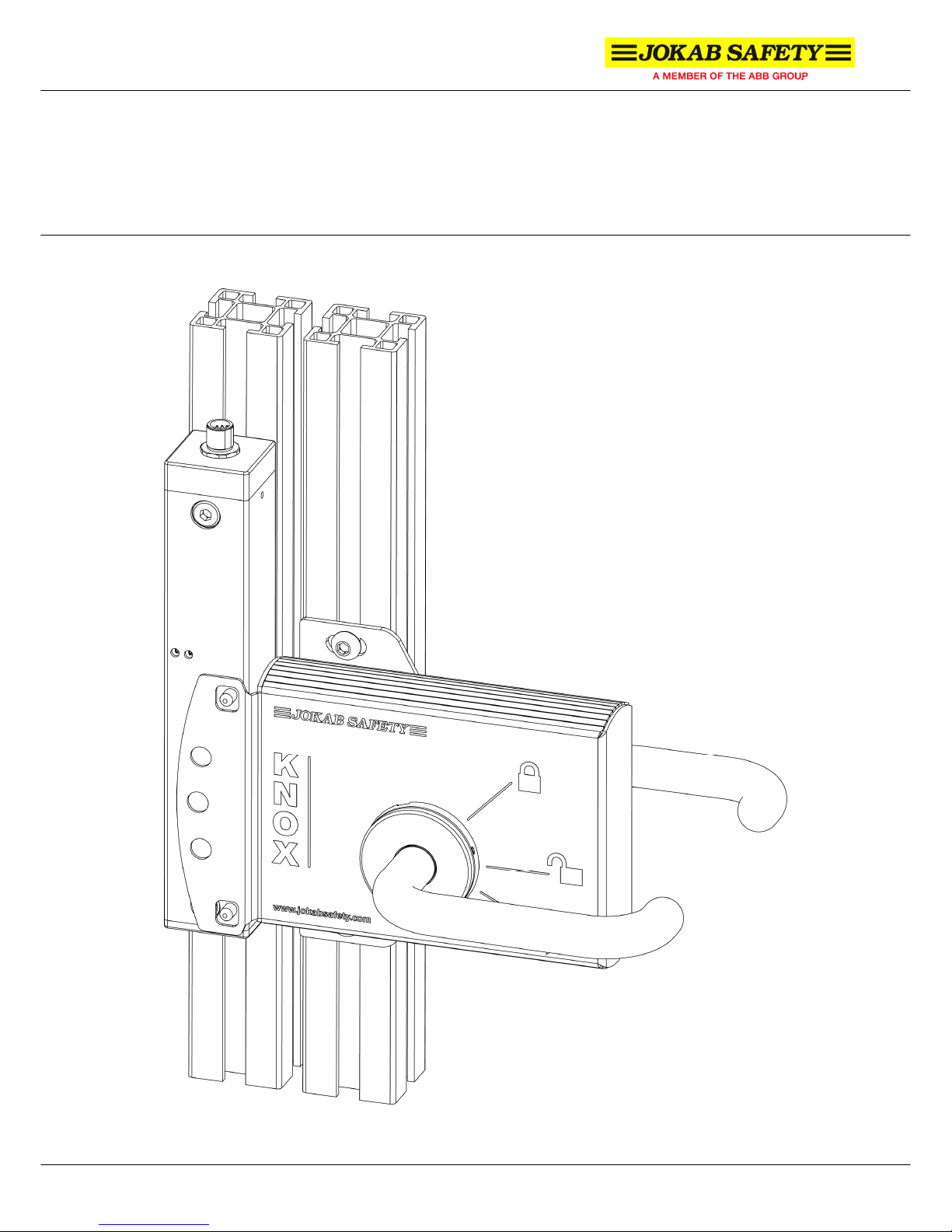
Knox
Safety lock

Knox_Manual_(English)_v1B
www.jokabsafety.com
2010-10-01
2
Table of Contents
1 Introduction.............................................................................................................................. 3
Scope .................................................................................................................................................. 3
Audience ............................................................................................................................................. 3
Prerequisites ....................................................................................................................................... 3
Special notes....................................................................................................................................... 3
2 Overview...................................................................................................................................4
General description ............................................................................................................................. 4
Safety regulations ............................................................................................................................... 4
Function description ............................................................................................................................ 5
3 Connections............................................................................................................................. 6
Connection examples.......................................................................................................................... 7
4 Installation and maintenance ................................................................................................. 9
Assembly instructions ....................................................................................................................... 11
Installation precautions ..................................................................................................................... 11
Maintenance...................................................................................................................................... 11
5 Operation................................................................................................................................ 12
LED indication ................................................................................................................................... 12
6 Model overview...................................................................................................................... 13
Accessories ....................................................................................................................................... 14
7 Technical data........................................................................................................................ 15
Dimensions........................................................................................................................................ 16
CAD model........................................................................................................................................ 17
8 EC Declaration of conformity ............................................................................................... 18

Knox_Manual_(English)_v1B
www.jokabsafety.com
2010-10-01
3
1 Introduction
Scope
The purpose of these instructions is to describe the safety lock Knox and to provide the necessary
information required for assembly, installation, checks and adjustments after installation, and
maintenance. The instructions also include information necessary to connect Knox to a safety circuit.
Note that Knox can be connected to both Vital and Pluto, but specific connection examples are left out
of these instructions and can be found at www.jokabsafety.com or in the Safety Handbook.
Audience
This document is intended for authorized installation personnel.
Prerequisites
It is assumed that the reader of this document has knowledge of the following:
• Basic knowledge of Jokab Safety products.
• Knowledge of safety devices and safety locks.
• Knowledge of machine safety.
Special notes
Pay attention to the following special notes in the document:
Warning!
Danger of severe personal injury!
An instruction or procedure which, if not carried out correctly, may result in
injury to the technician or other personnel.
Caution!
Danger of damage to the equipment!
An instruction or procedure which, if not carried out correctly, may damage the
equipment.
NB: Notes are used to provide important or explanatory information.

Knox_Manual_(English)_v1B
www.jokabsafety.com
2010-10-01
4
2 Overview
General description
Knox is a double lock that complies with the highest safety level (two lock cylinders with monitored
positions) that can be used both as a safety and process lock. The locking function is electronically
controlled and is bi-stable, i.e. it retains its position (unlocked/locked) in the event of a power failure.
The handles operate as they would on a normal door apart from the exterior handle also having a
reset function reducing the need for an extra reset button for this device, and an interior handle that
can be used for emergency opening. Its design and durability mean that it is ideal for harsh
environments as the sensors in the lock are non-contact and the lock is manufactured of stainless
steel. Shielded cable is recommended between this unit and the rest of the safety circuits.
Safety regulations
Warning!
Carefully read through this entire
manual before using the device.
The devices shall be installed by a trained electrician following the Safety regulations, standards and
the Machine directive.
Failure to comply with instructions, operation that is not in accordance with the use prescribed in these
instructions, improper installation or handling of the device can affect the safety of people and the
plant.
For installation and prescribed use of the product, the special notes in the instructions must be
carefully observed and the technical standards relevant to the application must be considered.
In case of failure to comply with the instructions or standards, especially when tampering with and/or
modifying the product, any liability is excluded.

Knox_Manual_(English)_v1B
www.jokabsafety.com
2010-10-01
5
Function description
• “Open”: Door open, outer handle pressed down and emergency handle in horizontal position.
• “Reset, openable”: The safety device is reset but the door is unlocked and can be opened
from either side. Outer handle in upward position and emergency handle turned upwards
slightly from the horizontal position.
• “Emergency opened”: Door emergency opened. The door can always be opened from the
unsafe side. The door unlocks and the safety circuit is opened when the emergency handle is
pressed down, independent of the outer handle position.
• “Operational mode”: Door is locked and reset, closing the safety circuit (i.e. allowing a
process to start). Both handles in upward position. The door can only be opened from the
unsafe side (using the emergency handle) causing the process to stop.
Reset, openable
Emergency opened
Operational mode; locked and reset
(emergency opening only)
Opened

Knox_Manual_(English)_v1B
www.jokabsafety.com
2010-10-01
6
3 Connections
Caution! All cable colours according to Jokab Safety standard cable.
Warning! Knox has an information output able to indicate if the door is locked or not. There is also a
built-in Eden sensor which also has an information output for indication. All information channel
outputs are non-safe and must therefore never
be used to control a safety application. To control a
safety application the safe
dynamic signals from Eden must be used to determine if a door is locked or
not.
Warning! The system must be connected using a fuse of max 6A.
8-pole M12-connector:
(1) White: Dynamic input signal
(2) Brown: +24 VDC
(3) Green: Lock
(4) Yellow: Lock inverse
(5) Grey: Information Locked
(6) Pink: Dynamic output signal
(7) Blue: 0 VDC
(8) Red: Information Reset
M12 8-pole female
seen from cable side
M12 8-pole male
seen from cable side
 Loading...