

jokab safety Dalton Original Instructions Manual
Original instructions
Dalton
Process lock
2TLC172165M0201, rev. A
ABB AB / Jokab Safety Varlabergsvägen 11, SE-434 39, Sweden
www.jokabsafety.com

Read and understand this document
Please read and understand this document before using the products. Please consult your ABB/JOKAB SAFETY
representative if you have any questions or comments.
WARRANTY
ABB/JOKAB SAFETY’s exclusive warranty is that the products are free from defects in materials and workmanship
for a period of one year (or other period if specied) from date of sale by ABB/JOKAB SAFETY.
ABB/JOKAB SAFETY MAKES NO WARRANTY OR REPRESENTATION, EXPRESS OR IMPLIED, REGARDING
NON-INFRINGEMENT, MERCHANTABILITY, OR FITNESS FOR PARTICULAR PURPOSE OF THE PRODUCTS,
ANY BUYER OR USER ACKNOWLEDGES THAT THE BUYER OR USER ALONE HAS DETERMINED THAT THE
PRODUCTS WILL SUITABLY MEET THE REQUIREMENTS OR THEIR INTENDED USE. ABB/JOKAB SAFETY
DISCLAIMS ALL OTHER WARRANTIES, EXPRESS OR IMPLIED.
LIMITATIONS OF LIABILITY
ABB/JOKAB SAFETY SHALL NOT BE RESPONSIBLE FOR SPECIAL, INDIRECT, OR CONSEQUENTIAL
DAMAGES, LOSS OF PROFITS OR COMMERCIAL LOSS IN ANY WAY CONNECTED WITH THE PRODUCTS,
WHETHER SUCH CLAIM IS BASED ON CONTRACT, WARRANTY, NEGLIGENCE, OR STRICT LIABILITY.
In no event shall responsibility of ABB/JOKAB SAFETY for any act exceed the individual price of the product on
which liability asserted.
IN NO EVENT SHALL ABB/JOKAB SAFETY BE RESPONSIBLE FOR WARRANTY, REPAIR, OR OTHER CLAIMS
REGARDING THE PRODUCTS UNLESS ABB/JOKAB SAFETY’S ANALYSIS CONFIRMS THAT THE PRODUCTS
WERE PROPERLY HANDLED, STORED, INSTALLED, AND MAINTAINED AND NOT SUBJECT TO ABUSE,
MISUSE, OR INAPPROPRIATE MODIFICATION OR REPAIR.
SUITABILITY FOR USE
ABB/JOKAB SAFETY shall not be responsible for conformity with any standards, codes, or regulations that apply to
the combination of products in the customer’s application or use of the product.
At the customer’s request, ABB/JOKAB SAFETY will provide applicable third party certication documents identifying
ratings and limitations of use that apply to the products. This information by itself is not sufcient for a complete
determination of the suitability of the products in combination with the end product, machine, system, or other
application or use.
The following are some examples of applications for which particular attention must be given. This is not intended
to be an exhaustive list of all possible uses of the products, nor is it intended to imply that the uses listed may be
suitable for the products:
Outdoor use, uses involving potential chemical contamination or electrical interference, or conditions or uses not
described in this document.
Nuclear energy control systems, combustion systems, railroad systems, aviation systems, medical equipment,
amusement machines, vehicles, and installations subject to separate industry or government regulations.
Systems, machines, and equipment that could present a risk to life or property.
Please know and observe all prohibitions of use applicable to the products.
NEVER USE THE PRODUCTS FOR AN APPLICATION INVOLVING SERIOUS RISK TO LIFE OR PROPERTY
WITHOUT ENSURING THAT THE SYSTEM AS A WHOLE HAS BEEN DESIGNED TO ADDRESS THE RISKS, AND
THAT THE ABB/JOKAB SAFETY PRODUCT IS PROPERLY RATED AND INSTALLED FOR THE INTENDED USE
WITHIN THE OVERALL EQUIPMENT OR SYSTEM.
PERFORMANCE DATA
While every effort has been taken to ensure the accuracy of the information contained in this manual ABB/
JOKAB SAFETY cannot accept responsibility for errors or omissions and reserves the right to make changes
and improvements without notice.Performance data given in this document is provided as a guide for the user in
determining suitability and does not constitute a warranty. It may represent the result of ABB/JOKAB SAFETY’S test
conditions, and the users must correlate it to actual application requirements. Actual performance is subject to the
ABB/JOKAB SAFETY Warranty and Limitations of Liability.
2TLC172165M0201, rev. A www.jokabsafety.com
2

The Dalton process lock complies with CE provisions according to the following directives:
EMC Directive 2004/108/EC
MANUFACTURER: ABB AB / JOKAB SAFETY
Varlabergsvägen 11
434 39 Kungsbacka
SWEDEN
Phone +46 (0)40 6715600
FAX +46 (0)40 6715601
E-Mail info@jokabsafety.com
USER’S MANUAL: Original instructions
Revision A dated 2011-10-20
www.jokabsafety.com 2TLC172165M0201, rev. A
3

Table of contents
1 Dalton - the intelligent process lock ..............................................6
1.1 Basic versions ........................................................................................... 6
2 General information .........................................................................7
2.1 Installation precautions ............................................................................. 7
2.2 Maintenance .............................................................................................. 7
2.3 Caution! ..................................................................................................... 7
2.4 In case of functional problems .................................................................. 7
2.5 Force to open ............................................................................................ 7
3 Mechanical design ...........................................................................8
3.1 Opening directions .................................................................................... 8
3.2 Detection of tongue ................................................................................... 9
3.3 Location of tongue towards Dalton ............................................................ 9
3.4 Adjustment of tongue .............................................................................. 10
3.5 Distance from hinge to tongue ................................................................ 11
3.6 Vertical installation .................................................................................. 12
3.7 Horizontal installation .............................................................................. 12
4 Electrical connections ...................................................................13
5 Connection examples ....................................................................14
6 Distribution blocks and special cables ........................................16
6.1 Distribution block Tina 12A ...................................................................... 16
6.2 Transfer cables ........................................................................................ 16
7 Dalton in combination with brackets ...........................................17
7.1 The basic Dalton versions ....................................................................... 17
7.2 Mounting brackets for Dalton .................................................................. 17
7.3 Mounting brackets for Dalton and Eden .................................................. 18
7.4 Mounting brackets for ABB/Jokab Safety Quick-Guard fence ................. 18
7.5 Mounting brackets with small bracket for tongue .................................... 19
7.6 Tongue .................................................................................................... 19
2TLC172165M0201, rev. A www.jokabsafety.com
4

8 Assembly of Dalton and mounting bracket .................................20
9 Measurements ................................................................................21
9.1 Dalton with bracket 1 ............................................................................... 21
9.2 Dalton with bracket 2 ............................................................................... 21
9.3 Dalton with bracket 3 ............................................................................... 22
9.4 Dalton with bracket 4 ............................................................................... 22
9.5 Dalton with bracket 5 ............................................................................... 23
9.6 Dalton with bracket 6 ............................................................................... 23
10 Technical data ................................................................................24
10.1 Indication and information ....................................................................... 24
10.2 Connectors .............................................................................................. 24
10.3 Pins (colour markings) ............................................................................ 24
10.4 Data ......................................................................................................... 25
www.jokabsafety.com 2TLC172165M0201, rev. A
5

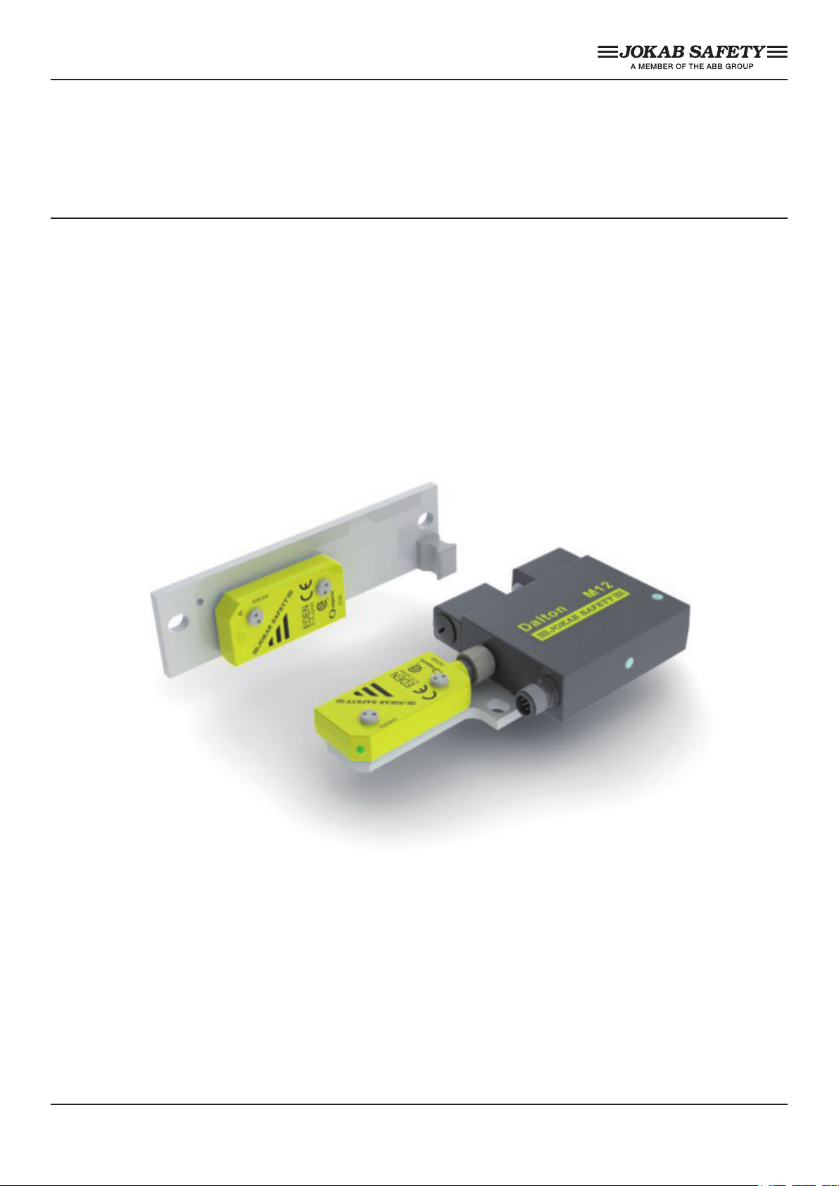
1 Dalton - the intelligent process lock
Dalton is a locking unit that is intended for use in preventing unnecessary production stoppages,
i.e. it is not a safety lock. It can be used either as a stand-alone lock or integrated with Eden
(as a safety sensor). In the unlocked state the door is held closed by a ball catch and locked
mechanically. If necessary, the holding force of the ball catch can be adjusted. The unit only
permits locking if the ball catch is secured and when Eva is in contact with Adam (depending on
variant). When the lock input is set, the ball catch is locked.
Dalton is easily connected with an M12 connector. A Tina junction block may also be used for
distribution of the safety as well as locking functions. The Dalton status is indicated by LEDs and
can also be read by PLC via the information output.
1.1 Basic versions
Four major versions of Dalton are available and can be combined with several mounting brackets.
There are different types of Dalton depending on the actual requirements. The L-type is a ball
catch without internal electronics. The M-type is a process lock with power to lock. There is a
possibillity to choose between three versions of the M-type. Two versions with 8-pole connectors.
The Dalton M11 without possibillity for connecting Eden and Dalton M12 with a 5-pole connector
for Eden and easilly distributed back to the electrical cabinet with the 8-pole cable including the
functions needed controlling the Dalton. The M31 has a 5-pole connector (otherwise the same as
M11) and the L00 version is without internal electronics.
Dalton M11 Dalton M12
Dalton M31 Dalton L00
2TLC172165M0201, rev. A www.jokabsafety.com
6

2 General information
2.1 Installation precautions
The Dalton lock shall be installed by trained personnel following the Safety regulations, standards
and the Machine directive. All safety functions shall be tested before the starting up of the
machine.
2.2 Maintenance
Before performing maintenance - Do not open the Dalton prior the warranty has elapsed. Opened
units will not be given warranty if claims are made.
The ball-catch is lubricated from factory. More lubrication can be added when needed. Dismount
the end caps and adjustment screws. Remove the springs, pistons and balls. Add grease on the
ball seat, springs, pistons and balls.
Remount the details.
Warning! The piston o-rings may not be damaged. This will have an negative effect on the IPrating.
2.3 Caution!
This product shall be handled with caution. The product should be replaced with the same type of
product if there is a situation where it has been dropped on the oor, knocked strongly, exposed
to extreme voltages, temperatures or humidity beyond the specied limits. Dalton may never be
used as a door stop.
2.4 In case of functional problems
The entire system should be tested without disconnecting the power supply. Check the LED
indicators according to ”Indication and information” under the chapter ”Technical data“ in this
manual. If the problem is not solved, please contact the nearest ABB/Jokab Safety Service Ofce
or reseller.
2.5 Force to open
Do not attempt to force the lock open while Dalton is locked, as it will cause permanent damage
to the device.
www.jokabsafety.com 2TLC172165M0201, rev. A
7

3 Mechanical design
Depending on the mounting brackets, the Dalton can be mounted with opening from two or three
directions. These three directions are shown below and will be mentioned further on in the text.
Top Front Bottom
3.1 Opening directions
The mounting brackets are designed to make it possible to adjust the position of the tongue in the
ball-catch.The ball-catch may not be in tension with the tongue when the lock is to be activated.
This is to ensure function without problems.
Note! Dalton may never be used as a door stop.
Only two opening directions with this kind of mounting bracket (Bottom and Front).
2TLC172165M0201, rev. A www.jokabsafety.com
8

3.2 Detection of tongue
To ensure that the Dalton will be able to detect the tongue the right type of tongue has to be
selected. For approach from Front select tongue A and for approach from Top and Bottom select
tongue B. Any of the two tongues can be used for either operating direction when used together
with Dalton L00.
The tongues are recognised by their physical marks (see pictures bellow).
Tongue A Tongue B
3.3 Location of tongue towards Dalton
The tongue has to be mounted correctly to ensure optimized detection towards Dalton. The
smallest of the two screws on the back side of the mounting bracket for the tongue must always
be heading towards Dalton or downwards (see pictures below).
Top
(Tongue B)
www.jokabsafety.com 2TLC172165M0201, rev. A
Front
(Tongue A)
9
Bottom
(Tongue B)
 Loading...