

Page 1
User Manual
JS-ICON™ Series
Dimmer/Relay Rack
JS-ICON™ 2410
JS-ICON™ 2413
JS-ICON™ 1220
JS-ICON™ 1210/620
JOHNSON SYSTEMS INC.
www.johnsonsystems.com
2002161
Page 2
Contents
Warranty ..........................................................................................................2
For Technical Assistance .................................................................................2
Introduction ......................................................................................................3
Characteristics .................................................................................................4
Installation .......................................................................................................5
Power Supply Connection Details ...................................................................6
Ground Connection Details .............................................................................8
Dimmer Output ................................................................................................9
Control Input/Output ......................................................................................10
MADD-24 (Multiple Application Dimmer Driver) ............................................11
User Interface ................................................................................................12
System Status - LED Indicators.....................................................................13
System Status - LCD Display ........................................................................13
Quick Programming Reference to System Conguration Menu Items ..........15
Detailed Programming of System Conguration Menu Items........................16
Important Hard-key Information .....................................................................31
Troubleshooting Reference ...........................................................................32
Warranty
JS-ICON™ Series dimmer racks come with a standard 1 year limited
warranty. Extended warranties of up to 10 years are available at the time of
purchase. For details visit www.johnsonsystems.com/warranties.htm.
For Technical Assistance
1. Refer to your product user manual. The most current revision is
available online: www.johnsonsystems.com/literature.htm
2. Contact the “point-of-sale” dealer or distributor from which this product
was originally purchased, and ask for technical assistance.
3. If neither of the above can provide you with the necessary information,
please contact our factory via email ([email protected])
or phone (403-287-8003) during business hours (Monday to Friday,
8:00AM to 5:00PM MST).
2
www.johnsonsystems.com
Page 3
Introduction
JS-ICON™ Series wall-mount dimmer racks represent the ultimate
value in hi-performance dimming! Next generation “system-on-a-chip”
technology coupled with state-of-the-art inductor technology provides
unsurpassed quality in professional grade SCR dimming.
Advanced next generation hardware and software designs reduce
stand-by power consumption to less than 1 Watt, allowing for
compliance with the International Energy Agency’s “One Watt
Initiative” for standby power consumption. This makes JS-ICON™
Series the “greenest” dimmer racks available!
Available in a number of different sizes and congurations, JS-ICON™
Series dimmer racks are designed for side-by-side installation and
high density requirements. Intuitive LCD user interface combined with
dual DMX inputs, analog inputs and contact closure inputs allow for
industry wide application.
Removable cover allows for ease of installation and serviceability.
On demand “MagLev®” thermal management technology produces
superior cooling that is virtually silent making JS-ICON™ the natural
choice for “quiet space” dimming installations. Exclusive “lamp
warming” techniques extends lamp life considerably while maintaining
industry leading performance!
• Available in multiple sizes and congurations.
• Unique power saving “stand-by” mode reduces power
consumption to less than 1 Watt. Compliance with the “One Watt
Initiative”.
• Dims standard or low-voltage incandescent quartz lamps.
• Individual dimmer prole selection permits safe and silent nondim control of uorescent loads, HID lighting, motors, etc.
• Dual DMX512-A inputs with on-board protocol manager.
Optional wireless DMX receiver.
• Unique “lamp warming” feature extends lamp life.
• Analog and dedicated dry contact BMS inputs for interface with
HVAC, security and audio.
• LCD user interface for easy setup and monitoring.
• Over-heat and over-current protected.
• Non proprietary dimmer SCR’s are 200% rated.
• On-demand ‘MagLev®’ thermal management technology
produces superior cooling that is virtually silent.
• “Load Shed” inputs for power management and photocell
interface.
• Up to 10 year product warranty available!
www.johnsonsystems.com 3
Page 4
Characteristics
• Maximum Feeder Capacity: 100 Amp 120/208 VAC 3Ø 5 wire. Max.
Rating 28.8kW. 100 Amp 120/240 VAC 1Ø 4 wire. Max. Rating 24.0kW.
• Power Termination: Power lug input. Terminal block output.
• Environment: Temperature Range: 23°F (-5°C) to 104°F (40°C) ambient.
Humidity Range: 0% to 90% non-condensing.
• Dimmer Load Type: Incandescent quartz lamps and electronic
(SCR dimmable) low voltage xtures.
• Relay Load Type: Any to maximum circuit rating.
• Switch Type: 200% rated, non-proprietary SCR solid state relay.
• Choke Type: High performance, copper wound, hybrid core toroidal
magnetic lter.
• Choke Rise Time: 2400W = 400µs; 1560W = 300µs; 1200W = 300µs.
• Physical: 30" x 17" x 6.8" (75 cm x 43 cm x 17 cm).
• Weight: All Models approximately 66 lbs. (30 Kg).
• Material: 18-gauge steel CRS.
• Finish: Textured ne black powder coat.
4
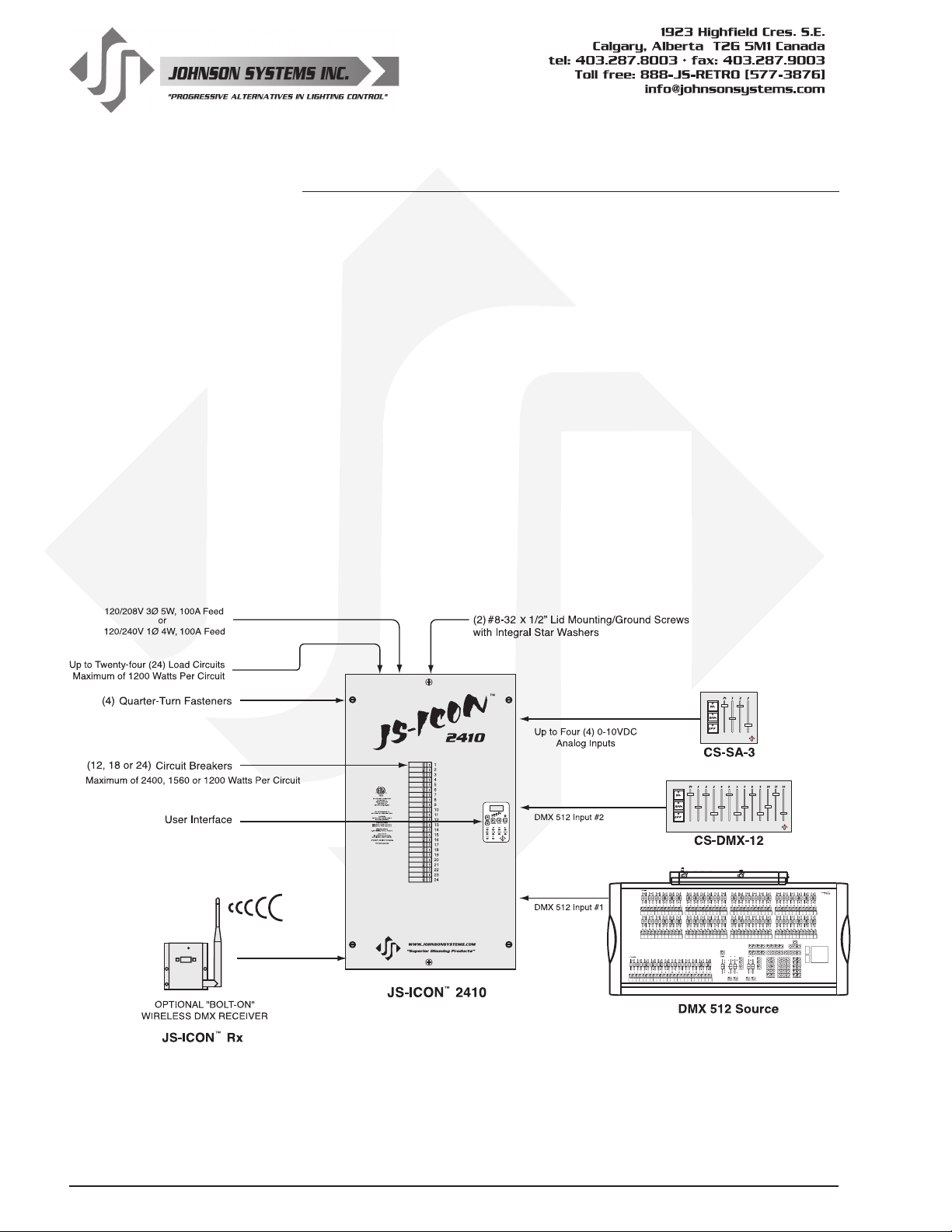
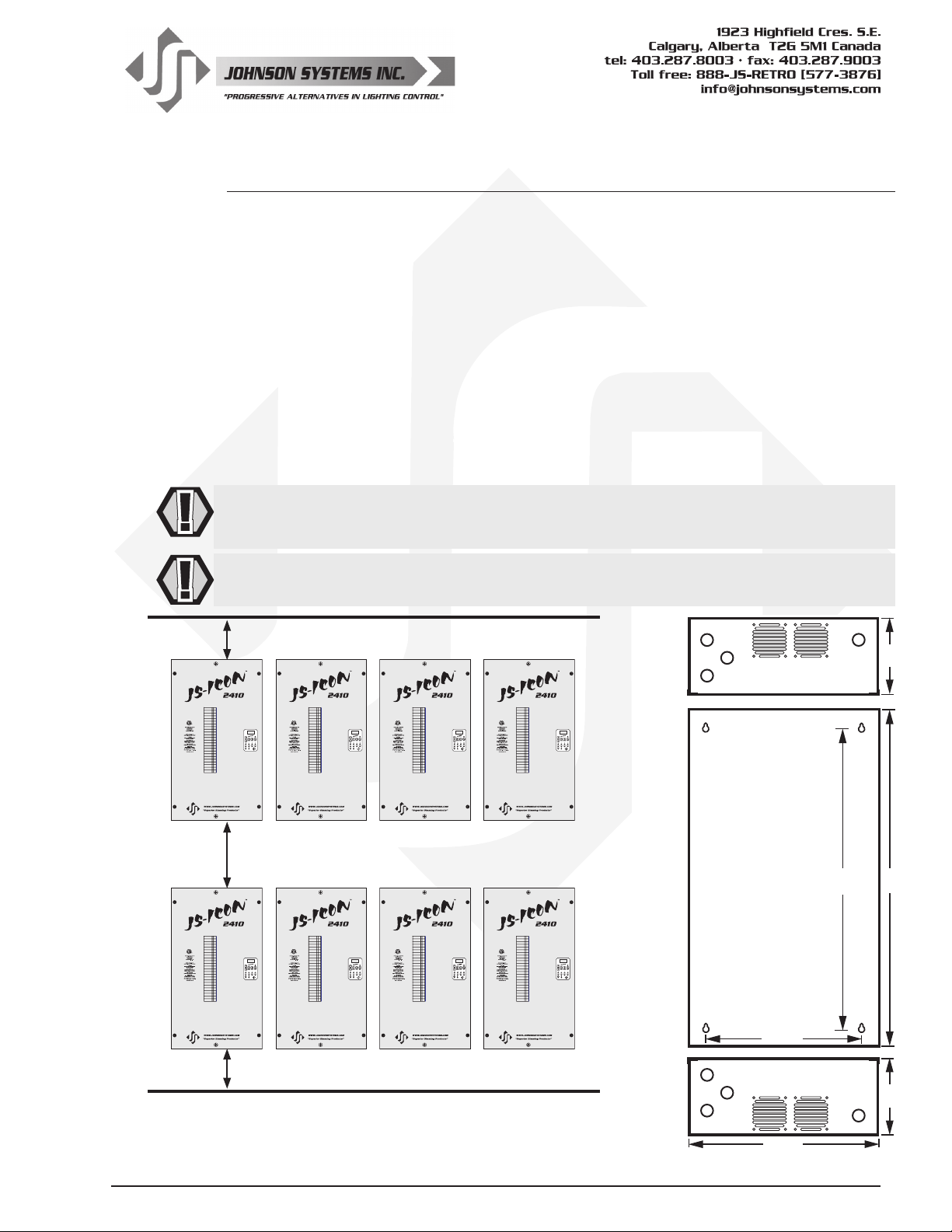
Typical System Installation
JS-ICON™ 2410 - Twenty-four (24) 10 AMP CCTS.
www.johnsonsystems.com
Page 5
Installation
Mounting
The JS-ICON Series dimmer racks can be mounted to any wall surface capable of supporting
its weight of approximately 66 lbs (30 kg) for each rack. Four 1/4" (6mm) screws or bolts are
required to fasten the rack safely to the wall (see the drawing below for mounting locations and
dimensions). To access the mounting locations, simply remove the lid. The lid is secured by two
(2) #8-32 x 1/2" lid mounting/ground screws with integral star washers located at the top-center
and bottom-center of the lid, as well as four (4) quarter-turn fasteners located in each corner.
Use a #2 Philips screwdriver to remove the two (2) lid mounting/ground screws. To release the
four (4) quarter-turn fasteners, use a athead screwdriver to turn them a quarter-turn counter-
clockwise. Once the lid mounting/ground screws are removed and the fasteners are released,
the lid can be removed. When remounting the lid, it is very important to re-install and tighten the
two (2) mounting/ground screws to ensure ground continuity from the main chassis/enclosure to
the lid. The quarter-turn fasteners are easily locked into place by lining the slot up horizontally,
and pushing it in with a thumb.
WARNING: Risk of electrical shock. Before the power supply is turned on, ensure the lid is
securely fastened to the rack with the two (2) lid mounting/ground screws and four (4) quarterturn fasteners. Never remove the lid when the power supply is turned on.
WARNING: Mount the dimmer racks only as indicated below. Failure to comply may cause
thermal overheating.
12" Minimum Clearance for Hot Air Exhaust
6.80"
TOP VIEW
O/OFF
I/ON
1
O/OFF
2
O/OFF
I/ON
3
O/OFF
I/ON I/ON
4
O/OFF
I/ON
5
O/OFF
I/ON
6
O/OFF
7
2002161
O/OFF O/OFF
I/ON
8
O/OFF
I/ON I/ON
9
I/ON
10
O/OFF
I/ON
11
O/OFF O/OFF
12
I/ON I/ON
13
O/OFF
I/ON
14
O/OFF
I/ON
15
O/OFF
I/ON
16
O/OFF
I/ON
17
O/OFF
I/ON
18
O/OFF
I/ON
19
O/OFF
I/ON
20
O/OFF
I/ON
21
O/OFF
I/ON
22
O/OFF
I/ON
23
O/OFF
I/ON
24
O/OFF
I/ON
1
O/OFF
2
O/OFF
I/ON
3
O/OFF
I/ON I/ON
4
O/OFF
I/ON
5
O/OFF
I/ON
6
O/OFF
7
2002161
O/OFF O/OFF
I/ON
8
O/OFF
I/ON I/ON
9
I/ON
10
O/OFF
I/ON
11
O/OFF O/OFF
12
I/ON I/ON
13
O/OFF
I/ON
14
O/OFF
I/ON
15
O/OFF
I/ON
16
O/OFF
I/ON
17
O/OFF
I/ON
18
O/OFF
I/ON
19
O/OFF
I/ON
20
O/OFF
I/ON
21
O/OFF
I/ON
22
O/OFF
I/ON
23
O/OFF
I/ON
24
O/OFF
I/ON
1
O/OFF
2
O/OFF
I/ON
3
O/OFF
I/ON I/ON
4
O/OFF
I/ON
5
O/OFF
I/ON
6
O/OFF
7
2002161
O/OFF O/OFF
I/ON
8
O/OFF
I/ON I/ON
9
I/ON
10
O/OFF
I/ON
11
O/OFF O/OFF
12
I/ON I/ON
13
O/OFF
I/ON
14
O/OFF
I/ON
15
O/OFF
I/ON
16
O/OFF
I/ON
17
O/OFF
I/ON
18
O/OFF
I/ON
19
O/OFF
I/ON
20
O/OFF
I/ON
21
O/OFF
I/ON
22
O/OFF
I/ON
23
O/OFF
I/ON
24
2002161
18" Minimum Clearance KEEP CLEAR
O/OFF
I/ON
1
O/OFF
2
O/OFF
I/ON
3
O/OFF
I/ON I/ON
4
O/OFF
I/ON
5
O/OFF
I/ON
6
O/OFF
7
O/OFF O/OFF
I/ON
8
O/OFF
I/ON I/ON
9
I/ON
10
O/OFF
I/ON
11
O/OFF O/OFF
12
I/ON I/ON
13
O/OFF
I/ON
14
O/OFF
I/ON
15
O/OFF
I/ON
16
O/OFF
I/ON
17
O/OFF
I/ON
18
O/OFF
I/ON
19
O/OFF
I/ON
20
O/OFF
I/ON
21
O/OFF
I/ON
22
O/OFF
I/ON
23
O/OFF
I/ON
24
REAR VIEW
30"27"
O/OFF
I/ON
1
O/OFF
2
O/OFF
I/ON
3
O/OFF
I/ON I/ON
4
O/OFF
I/ON
5
O/OFF
I/ON
6
O/OFF
7
2002161
O/OFF O/OFF
I/ON
8
O/OFF
I/ON I/ON
9
I/ON
10
O/OFF
I/ON
11
O/OFF O/OFF
12
I/ON I/ON
13
O/OFF
I/ON
14
O/OFF
I/ON
15
O/OFF
I/ON
16
O/OFF
I/ON
17
O/OFF
I/ON
18
O/OFF
I/ON
19
O/OFF
I/ON
20
O/OFF
I/ON
21
O/OFF
I/ON
22
O/OFF
I/ON
23
O/OFF
I/ON
24
O/OFF
I/ON
1
O/OFF
2
O/OFF
I/ON
3
O/OFF
I/ON I/ON
4
O/OFF
I/ON
5
O/OFF
I/ON
6
O/OFF
7
2002161
O/OFF O/OFF
I/ON
8
O/OFF
I/ON I/ON
9
I/ON
10
O/OFF
I/ON
11
O/OFF O/OFF
12
I/ON I/ON
13
O/OFF
I/ON
14
O/OFF
I/ON
15
O/OFF
I/ON
16
O/OFF
I/ON
17
O/OFF
I/ON
18
O/OFF
I/ON
19
O/OFF
I/ON
20
O/OFF
I/ON
21
O/OFF
I/ON
22
O/OFF
I/ON
23
O/OFF
I/ON
24
O/OFF
I/ON
1
O/OFF
2
O/OFF
I/ON
3
O/OFF
I/ON I/ON
4
O/OFF
I/ON
5
O/OFF
I/ON
6
O/OFF
7
2002161
O/OFF O/OFF
I/ON
8
O/OFF
I/ON I/ON
9
I/ON
10
O/OFF
I/ON
11
O/OFF O/OFF
12
I/ON I/ON
13
O/OFF
I/ON
14
O/OFF
I/ON
15
O/OFF
I/ON
16
O/OFF
I/ON
17
O/OFF
I/ON
18
O/OFF
I/ON
19
O/OFF
I/ON
20
O/OFF
I/ON
21
O/OFF
I/ON
22
O/OFF
I/ON
23
O/OFF
I/ON
24
O/OFF
I/ON
1
O/OFF
2
O/OFF
I/ON
3
O/OFF
I/ON I/ON
4
O/OFF
I/ON
5
O/OFF
I/ON
6
O/OFF
7
2002161
O/OFF O/OFF
I/ON
8
O/OFF
I/ON I/ON
9
I/ON
10
O/OFF
I/ON
11
O/OFF O/OFF
12
I/ON I/ON
13
O/OFF
I/ON
14
O/OFF
I/ON
15
O/OFF
I/ON
16
O/OFF
I/ON
17
O/OFF
I/ON
18
O/OFF
I/ON
19
O/OFF
I/ON
20
O/OFF
I/ON
21
O/OFF
I/ON
22
O/OFF
I/ON
23
O/OFF
I/ON
24
14"
12" Minimum Clearance for Cool Air Intake
BOTTOM VIEW
6.80"
17"
www.johnsonsystems.com 5
Page 6
∅A
∅B
∅C
Power Supply Connection Details
The JS-ICON™ Series dimmer racks are capable of various 120V power
supply congurations. The contractor termination section is located on the
left-hand side. Knockouts on the top and bottom of the chassis are provided
for wire/conduit entry to the power terminals. The phase power terminals
are mounted directly onto copper bussbars, used to distribute current to
each dimmers circuit breaker. The power terminals may be rotated up to 180
degrees to facilitate top or bottom wire entry. To rotate the power terminals,
loosen the 1/4-20 x 1/2" mounting bolts (use a 7/16" wrench or socket), rotate
terminals into place, and tighten the mounting bolts to 45-50 IN-LBS (5.0-5.6 NM).
WARNING: Wiring termination must be done by qualied personnel only!
WARNING: Be sure all power connections are tightened to specication
before power supply is turned on.
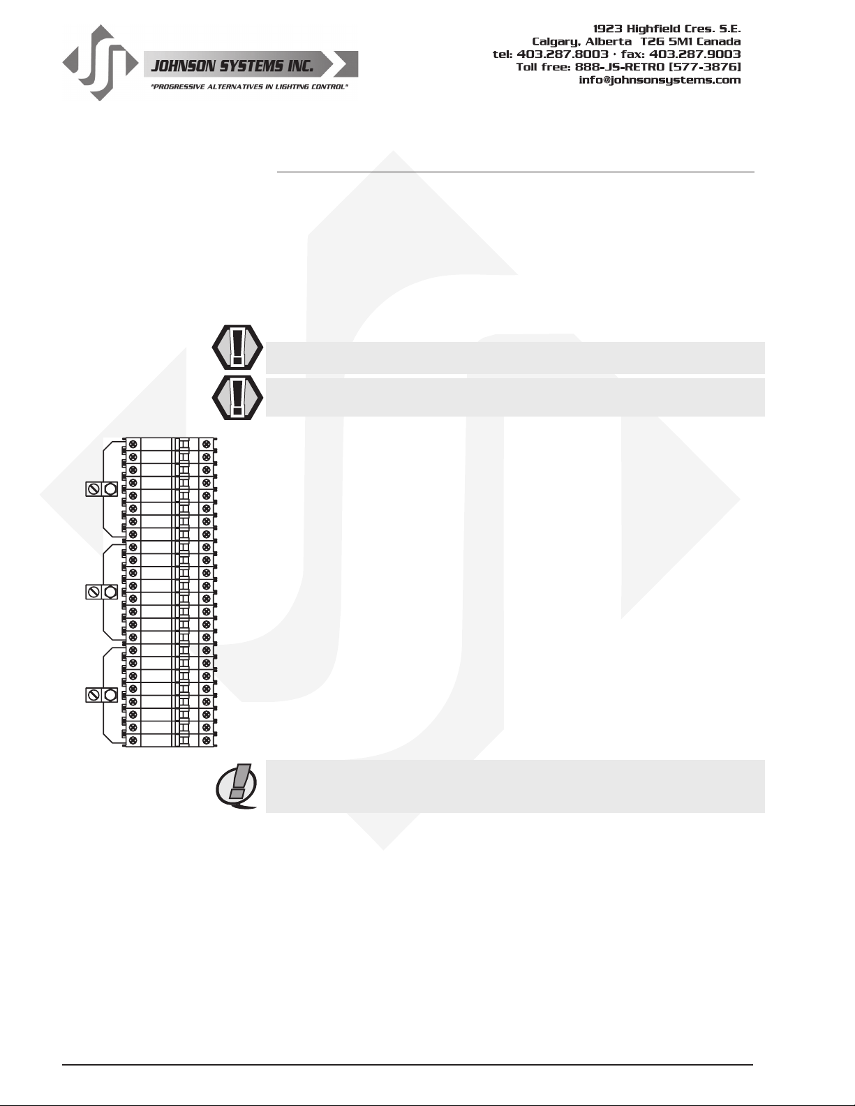
Power Supply Configurations - Three Phase:
120/208 VAC, 3Ø, 5-Wire up to 100 Amps per phase. Maximum 28.8kW total.
Use wire size #14 to #1/0 AWG. Strip insulation length to 0.65" (16.5mm).
Torque power terminals (A, B, C) to 45-50 IN-LBS (5.0-5.6 NM).
Below is the dimmer phasing for each JS-ICON™ Series dimmer rack model:
JS-ICON™ 2410 and JS-ICON™ 2413 (Example shown to the left)
• Dimmers 1 to 8 are powered from Phase A.
• Dimmers 9 to 16 are powered from Phase B.
• Dimmers 17 to 24 are powered from Phase C.
JS-ICON™ 1220
• Dimmers 1 to 4 are powered from Phase A.
• Dimmers 5 to 8 are powered from Phase B.
• Dimmers 9 to 12 are powered from Phase C.
JS-ICON™ 1210/620
• Dimmers 1 to 8 are powered from Phase A.
• Dimmers 9 to 14 are powered from Phase B.
• Dimmers 15 to 18 are powered from Phase C.
NOTE: Power supply requires an external disconnect.
NOTE: For connection use copper wire only, rated 167°F (75°C) minimum.
6
www.johnsonsystems.com
Page 7
Power Supply Connection Details
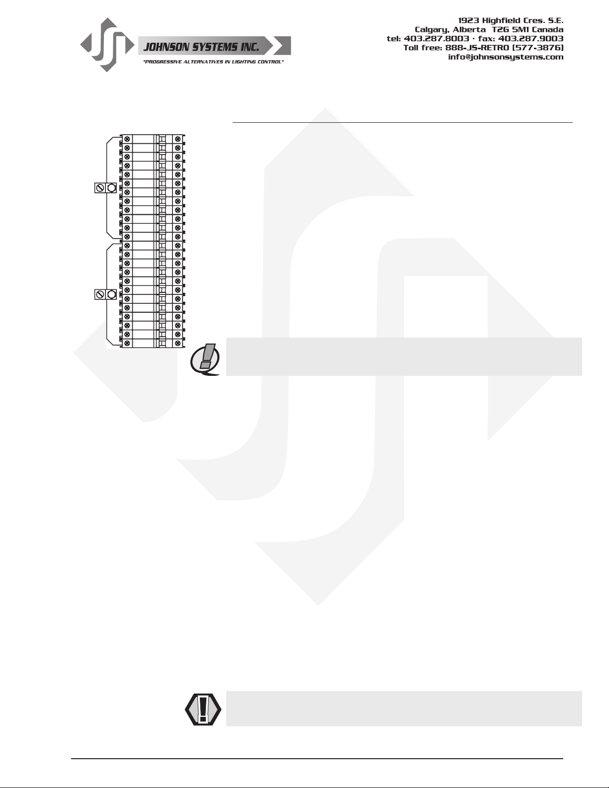
Power Supply Configurations - Single Phase:
120/240 VAC, 1Ø, 4-Wire up to 100 Amps per phase. Maximum 24.0kW total.
Use wire size #14 to #1/0 AWG. Strip insulation length to 0.65" (16.5mm).
Torque power terminals (A, B, C) to 45-50 IN-LBS (5.0-5.6 NM).
∅A
∅B
Below is the dimmer phasing for each JS-ICON™ Series dimmer rack model:
JS-ICON™ 2410 and JS-ICON™ 2413 (Example shown to the left)
• Dimmers 1 to 12 are powered from Phase A.
• Dimmers 13 to 24 are powered from Phase B.
JS-ICON™ 1220
• Dimmers 1 to 6 are powered from Phase A.
• Dimmers 7 to 12 are powered from Phase B.
JS-ICON™ 1210/620
• Dimmers 1 to 12 are powered from Phase A.
• Dimmers 13 to 18 are powered from Phase B.
NOTE: Power supply requires an external disconnect.
NOTE: For connection use copper wire only, rated 167°F (75°C) minimum.
Three-Phase to Single-Phase Conversion
JS-ICON™ Series dimmer racks are normally shipped for three-Phase
operation unless otherwise specied at the time of purchase. Please contact
your supplier for a single-phase conversion kit if required. The following steps
will need to be followed to convert the JS-ICON™ dimmer rack from three-
phase to single-phase operation.
1. Remove the three-phase copper bussbars by loosening all of the screws
terminals (use a medium sized #2 Philips or Flathead screwdriver) on
the left-hand side of the circuit breakers.
2. Insert the supplied single-phase copper bussbars, and tighten all of the
circuit breaker screw terminals to 20 IN-LBS (2.26 NM).
3. Reconnect the black #18 AWG wire (underneath) to the Phase A
bussbar.
4. Reconnect the red #18 AWG wire (underneath) to the Phase B bussbar.
5. Tape off or use a marette to isolate the blue #18 AWG wire.
6. Remove two (2) of the phase power terminals (use a 7/16" wrench or
socket) from the old three-phase bussbars, and fasten them to the new
single-phase bussbars. Use the original mounting bolts and tighten to
45-50 IN-LBS (5.0-5.6 NM).
7. Note that the default phase patch will need to be recongured when the
system is powered up. For more information, see “DEFAULTS” menu
item on page 30.
WARNING: Be sure all power connections are tightened to specication
before power supply is turned on.
www.johnsonsystems.com 7
Page 8
Load Circuit Neutral
Output Terminals
Power Supply Connection Details
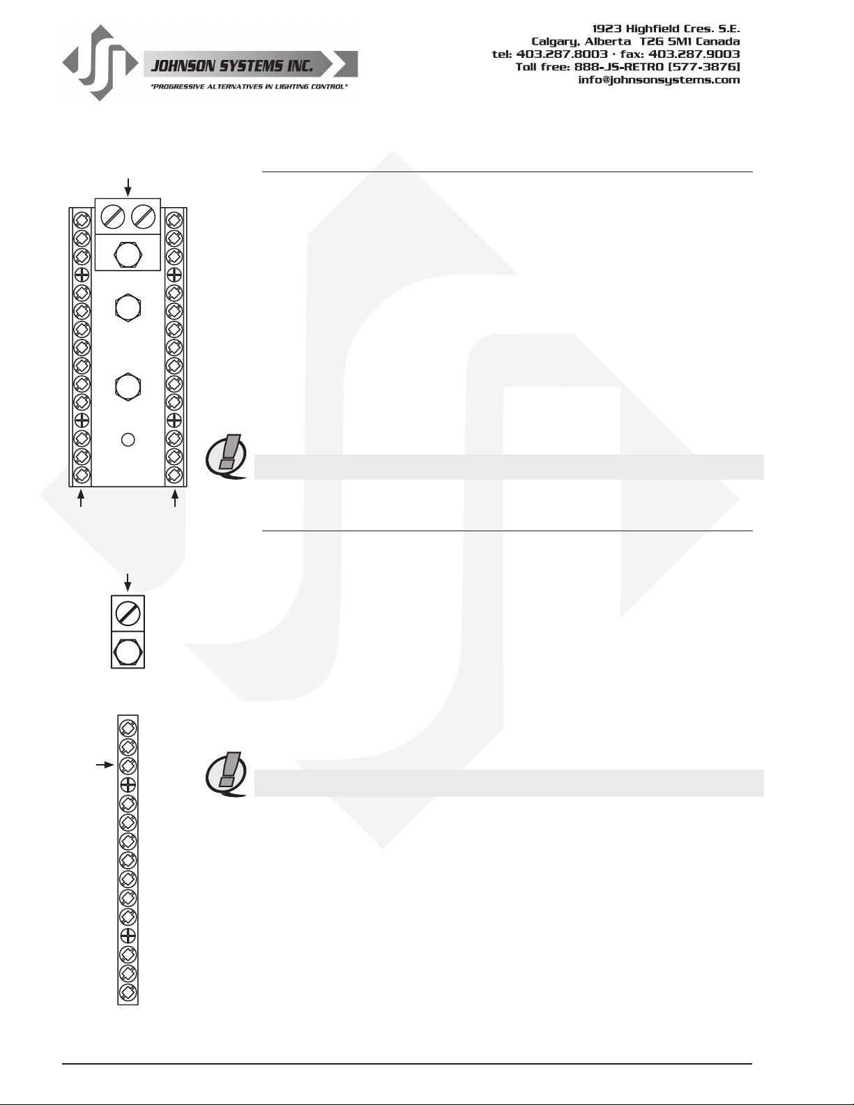
Neutral Power Distribution Block
Neutral Input Terminal
• Use wire size #14 to #1/0 AWG. Strip insulation length to 0.65" (16.5mm).
• Torque neutral terminal(s) to 45-50 IN-LBS (5.0-5.6 NM).
Capable of single or dual rated neutral termination. The neutral terminal may be
mounted on the top or bottom of the distribution block to facilitate top or bottom
wire entry. To change the position of the neutral terminal, remove the 1/4-20 x
1/2" mounting bolt (use a 7/16" wrench or socket), move into place, and tighten
the mounting bolt to 45-50 IN-LBS (5.0-5.6 NM).
Load Circuit Neutral Output Terminals
• Use wire size #14 to #8 AWG. Strip insulation length to 0.315" (8mm).
• Torque load circuit neutral terminals to 20-25 IN-LBS (2.3-2.8 NM).
Models JS-ICON™ 2410, JS-ICON™ 2413 and JS-ICON™ 1210/620 are supplied
with 25 load
NOTE: For connection use copper wire only, rated for 167°F (75°C) minimum.
circuit
neutral terminals, while Model JS-
ICON™ 1220 is supplied with 12.
Load Circuit Neutrals
Ground Input
Load
Circuit
Grounds
Ground Connection Details
Ground Input Terminal
• Use wire size #14 to #1/0 AWG. Strip insulation length to 0.65" (16.5mm).
• Torque ground terminal to 45-50 IN-LBS (5.0-5.6 NM).
The ground input terminal may be rotated up to 360 degrees to facilitate top or
bottom wire entry. To rotate the ground terminal, loosen the 1/4-20 lock-nut (use
a 7/16" wrench or socket), rotate terminal into place, and tighten the lock-nut to
45-50 IN-LBS (5.0-5.6 NM).
Load Circuit Ground Output Terminals
• Use wire size #14 to #8 AWG. Strip insulation length to 0.315" (8mm).
• Torque load circuit ground terminals to 20-25 IN-LBS (2.3-2.8 NM).
Models JS-ICON™ 2410, JS-ICON™ 2413 and JS-ICON™ 1210/620 are supplied
with 25 load circuit ground terminals, while model JS-
NOTE: For connection use copper wire only, rated for 167°F (75°C) minimum.
ICON™ 1220 is supplied with 12.
8
www.johnsonsystems.com
Page 9
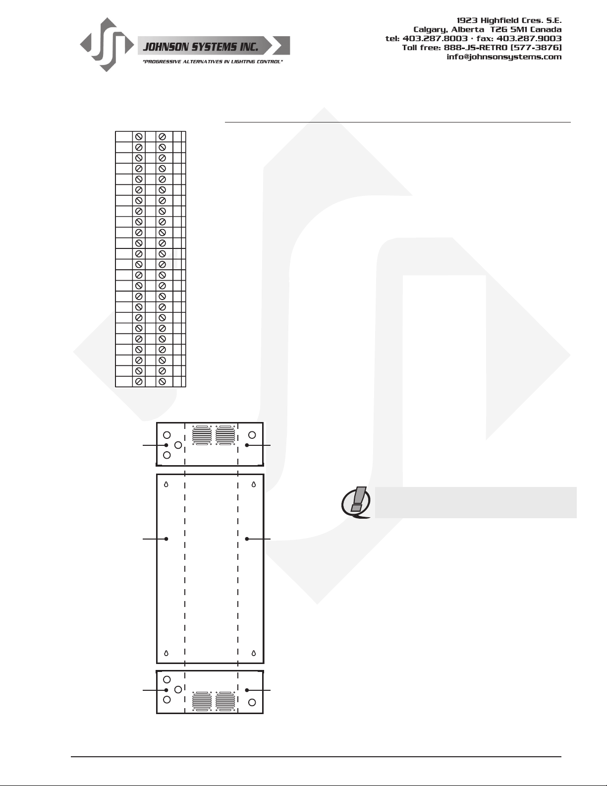
Load Output
Terminal Blocks
12 345 6789101311 12 14 15 16 17 18 19 20 21 22 23 24
Line Voltage
AC Wire / Conduit
Entry
Dimmer Output
JS-ICON™ 2410 24 x 10 Amp (1200 Watt) dimmers.
JS-ICON™ 2413 24 x 13 Amp (1560 Watt) dimmers.
JS-ICON™ 1220 12 x 20 Amp (2400 Watt) dimmers.
JS-ICON™ 1210/620 12 x 10 Amp (1200 Watt) and
6 x 20 Amp (2400 Watt) dimmers.
JS-ICON™ Series dimmer racks are designed for high performance dimming of
standard incandescent, quartz, and dimmable (SCR/Leading-Edge) electronic
low-voltage xtures. The dimmer outputs may be congured for non-dimmed
applications when switched (relay controlled) load outputs are required.
Knockouts on the top and bottom of the chassis are provided for wire/conduit
entry to the power terminals.
Load (Hot) Output Connection Details
Load output connections are terminated via DIN rail mounted terminal blocks.
Models JS-ICON™ 2410 and JS-ICON™ 2413
• Use wire size #14 to #10 AWG. Strip insulation length to 0.315" (8mm).
• Torque load output terminal blocks to 5-7 IN-LBS (0.6-0.8 NM).
Model JS-ICON™ 1220
• Use wire size #14 to #8 AWG. Strip insulation length to 0.4" (10mm).
• Torque load output terminal blocks to 13-16 IN-LBS (1.5-1.8 NM).
Model JS-ICON™ 1210/620
• For load output terminal blocks 1 to 12, use
Low Voltage
DC Wire / Conduit
Entry
TOP VIEW
same specication as Model JS-ICON
2410.
• For load output terminal blocks 13 to 18,
use same specication as Model JS-
ICON™ 1220.
™
Line Voltage
AC Contractor
Termination
Section
Line Voltage
AC Wire / Conduit
Entry
REAR VIEW
BOTTOM VIEW
NOTE: For connection use copper wire
only, rated for 167°F (75°C) minimum.
Low Voltage
DC Contractor
Termination
Section
Low Voltage
DC Wire / Conduit
Entry
www.johnsonsystems.com 9
Page 10
J24
J23
J18
J17
J33
J30
J29
J28
J27
J26
J21
J20
J19
J16J15
PS1
J1
J3
J2
J6
J4
J8J7 J10J9
J12
J5
J11
J14J13
J32
INPUT
VAC26485
WATTS15DCVOLTS12SUPPLYPOWER
TO
AUX
SCTY
FIRE
OCOP
+12V
COM
ANA4
ANA3
ANA2
ANA1
COM
BCN
CMD-D+CMD-D+CMD-D+CMD+
DMX A I/ODMX B I/O
BUMP
REMOTE
LCD AND LED STATUS
D-
A
1+
1-
2+
2-
A-
B-
C-
D-
++
UAD
SSR1
UAD
SSR2
DUAL
SSR1
DUAL
SSR2
UAD
SSR3
FAN1 FAN2
-
1+
1-
2+
2-
A-
B-
C-
D-
++
1+
1-
2+
2-
A-
B-
C-
D-
++
1+
1-
2+
2-
A-
B-
C-
D-
++
1+
1-
2+
2-
A-
B-
C-
D-
++
1+
1-
2+
2-
A-
B-
C-
D-
++
TERMO
TEMP
SENSOR
-STAT
LM35DT
+
-
FAN3 FAN4
+
-
UAD
SSR4
UAD
SSR5
UAD
SSR6
DUAL
SSR3
DUAL
SSR4
DUAL
SSR5
DUAL
SSR6
DUAL
SSR4
DUAL
SSR5
DUAL
SSR6
1210 620
NO
1+
1-
2+
2-
1+
1-
2+
2-
1+
1-
2+
2-
1210 6201210 620
Signal Distribution Board
SWITCH CONT
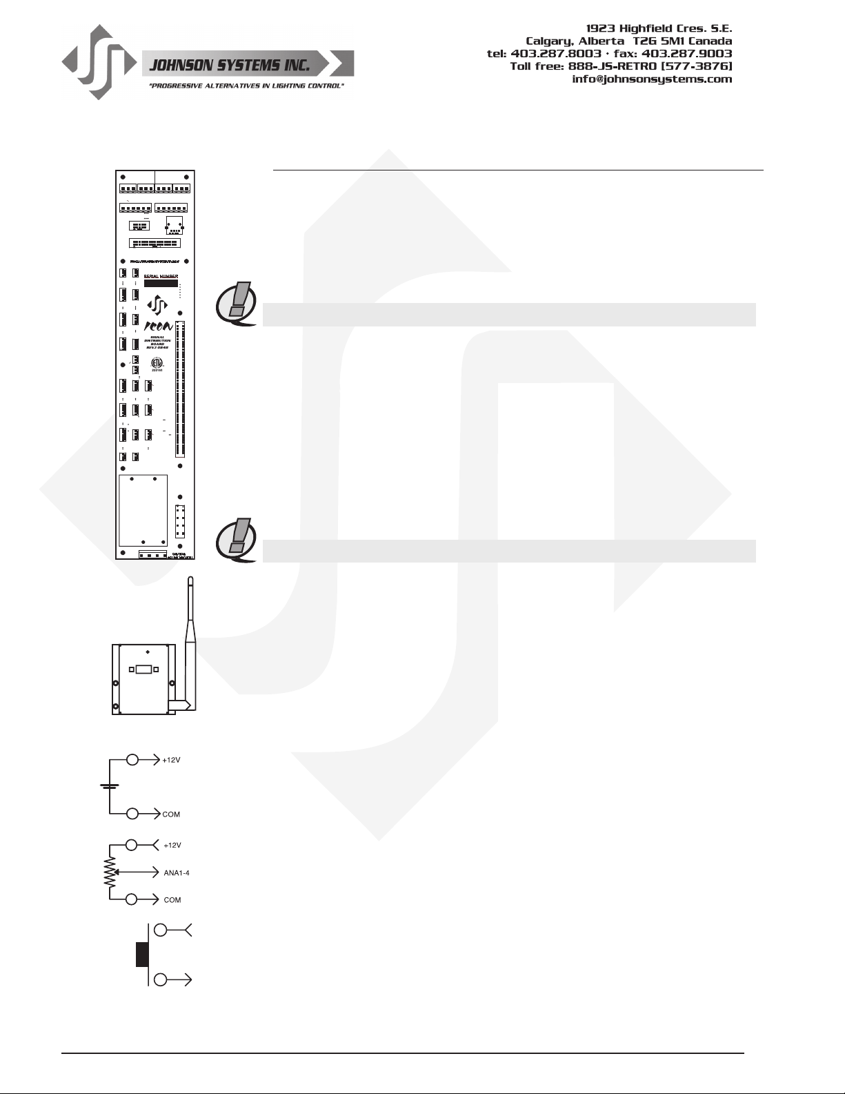
Control Input/Output
JS-ICON™ Series dimmer racks come with a variety of control input and output
(I/O) capabilities. All I/O connections are terminated on the Signal Distribution
Board, located on the right-hand side of the dimmer rack.
Breakaway type connectors are supplied for all I/O connections.
• Use wire size #28 to #12 AWG. Strip insulation length to 0.3" (7.5mm).
• Torque terminations to 3.6 IN-LBS (0.4 NM).
NOTE: For connection use copper wire only, rated for 167°F (75°C) minimum.
Dual DMX Input and Through
• DMX A terminates to J7 and J8 connectors.
• DMX B terminates to J9 and J10 connectors.
• Complies with USITT DMX512-A (ANSI E1.11 - 2008), Standard protocol
for digital data control.
• Recommended cable is Belden 9829, 9842, Cat 5 or equivalent
(low-capacitance, twisted pair).
• Wiring must follow a daisy-chain topology.
• Maximum of 32 receiving devices on a single DMX line.
• Maximum cable length is 1,500 feet (455 meters).
• For more information, Google DMX, or visit:
http://old.usitt.org/DMX512FAQ.aspx
NOTE: Ensure only the last (end-of-line) DMX receiving device is terminated!
MAINTAINED
NORMALLY OPEN
JS-ICON™ Rx
ACT
+12V
ANA1-4
Models JS-ICON™ Rx and JS-ICON™ Tx
Wireless DMX is optional for all JS-ICON™ Series dimmer racks. SHoW DMX
receiver (JS-ICON™ Rx) and transmitter (JS-ICON™ Tx) is sourced from City
Theatrical, and has been selected for its reliability and ease of use. The JSICON™ Rx is specically designed for easy adaptation to all JS-ICON™ products.
The JS-ICON™ Rx comes complete with a wiring harness and mounting
hardware. For more information visit:
http://www.johnsonsystems.com/JS-ICON_Rx_Manual_by_City_Theatrical.pdf.
+12VDC Power Supply Output
• A regulated +12VDC power supply is available for powering external
devices.
• Terminate on +12V and COM of J12 connector.
• External devices should not exceed the maximum combined current draw
of 200mA.
0-10VDC Analog Inputs or Load Shed Contact Inputs
• Four (4) analog inputs terminate on J12 connector.
• AN1=Analog Input 1, AN2=Analog Input 2, AN3=Analog Input 3,
AN4=Analog Input 4.
• Inputs can be congured for normal or load shed mode of operation.
• Inputs can be patched to any combination of dimmer output circuits.
•
Programmed in the “ANA MODE” and “ANA PTCH” menus. See page 22 for details.
10
www.johnsonsystems.com
Page 11
MAINTAINED
SWITCH CONT
O/T
EEPROM
NORMALLY OPEN
ACT
MAX
FIRE
SCTY
AUX
COM
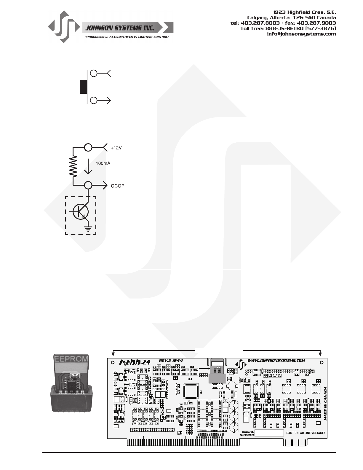
Over-Temperature Input (Normally Open)
• Terminate (O/T) on J11 connector.
• Disables all dimmer outputs when contact/switch is closed.
• Controlled via a maintained contact/switch to low-voltage common (COM).
Fire Alarm Input (Normally Open)
• Terminate (FIRE) on J11 connector.
• Triggers selected channels to turn on when contact/switch is closed.
• Controlled via a maintained contact/switch to low-voltage common (COM).
• Programmed in the “F-ALARM” menu. See page 25 for details.
Security Alarm Input (Normally Open)
• Terminate (SCTY) on J11 connector.
• Triggers selected channels to cycle on and off at a 1 Hertz rate.
• Controlled via a maintained contact/switch to low-voltage common (COM).
• Programmed in the “S-ALARM” menu. See page 24 for details.
Auxiliary Input (Normally Open)
• Terminate (AUX) on J11 connector.
• Triggers 1 of 24 presets when contact/switch is closed.
• Controlled via a maintained contact/switch to low-voltage common (COM).
• Programmed in the “AUX IN” menu. See page 24 for details.
Open Collector Output
• Terminate (OCOP) on J11 connector.
• Sink up to 100mA.
• Trigger Solid State Relays (SSR) or other external devices.
• Controlled via DMX and/or Analog Input 4.
• Programmed in the “OC MODE” menu. See page 23 for details.
MADD-24 (Multiple Application Dimmer Driver)
The MADD-24 is the central electronic control system (aka brain) for all JS-ICON™ Series dimmer racks.
The MADD-24 is located on the right-hand side of the dimmer rack, and mounts into card edge connectors
located on the Signal Distribution Board. The MADD-24 can easily be removed by unscrewing two #440 mounting screws (use a small sized #1 Philips screwdriver) located on the top corners, and pulling
it forward using both hands. When re-installing a MADD-24, be sure it is fully seated into the card edge
connectors, and the two mounting screws are screwed in tight.
Located on the MADD-24 is a removable EEPROM memory module. The EEPROM memory module
slides into the PORT1 connector located on the upper center of the board. The EEPROM memory module
is used to backup important conguration settings and may be removed for safe storage. The EEPROM
memory module can also be used for rmware updates. Refer to menu items “EEPROM”, “FW-LOAD”,
“RESTORE” and “BACKUP” on page 27 to 29 for further details.
Mounting Screws
EEPROM
1
MEMORY
R127 R126
C79
C78
MODULE
U50
U49
C61
R87
R86
R85
R121
U28
C65 C64
C63
X1
R68
R69
C80
U37
C81
U38
R66 R67
R75
R76
C89
R77
F5
R78
R84
PORT1
BACKUP &
FIRMWARE
C62
UPDATE
U29
TP4
C58
U33
U30
R79 R74
C59
R80
C60
U31
PWM
R81
R82
R83
R89 R88
TPA
TPB
C68
TPC
U51
CALIBRATE
D27
D28
C34
C33
T3
L1
D18
D17
U32
VR3
C53
Q7
U52 U53
U34
DC/FAN
C1
C2
C3
C54
C55
C57
C56
D26
U18
R134
R133
R132
R131
R130
C84
C83
R128
R129
U17
R52 R53
R54
U11
U13
U12
D2
D1
D3
R43 R46
U1
R3
C4
VR1
R1 R2
R51
R47
R48
R49
R50
R42
C24
R45
R44
C25
D6
U8
U9
C5
C26
C27
C28
R34
R5
R4
R38
R37
R36
R35
R33 R32
R31
C85
R141
R140
R139
R138
R137
R136
R135
Q11 Q10 Q9 Q8
C37
R57
U16
R29
C32 C31
C15
C16
C30
D5
U5
U6
U10
C17
C18
C29
R21
R22
R24
R23
R41
R40
R39
R18
R19 R20
R30
C87
U19
R145
R144
R143
R142
C86
C19
R25
VR5
C88
C36
R56
C35
U14
U15
R16
C6
C14 C13
C7
C21
C22 C23
U7
R26
R17
C12
D4
U2
U4
U3
C8
C9
C10
C20
R8
R9
R14
R13
R12
R11
R10
R28
R27
R7 R6
TP1
EDGE1
EEPROM
Memory Module
U20
U21
VR2
C40
R58
R59
C41
D9 D10 D11
F1 F2 F3 F4
RLY1
R60
Q4 Q3
D15
D16
R61
C38
C39
D12
BR2 BR1
TP3
1 BUMP REM
EDGE2
R63
U26 U25 U24 U23
RLY2
D7
D8
T5
U40
U41
U42
U43
D22
D21
D20
R108 R107
R106
C73
R95
R94
C72
R93
R92
C71
R91
R90
ANA I/O DMX LCD LED SWITCH
C42
C43
U22
Q1 Q2
D13
D14
C75
U46
R62
U45
R64 R65
R70 R71 C52
U27
R96
R122 R123
R124 R125
C76
C77
U47
U48
C51 C50
R146
R120
C67
R72 R73
C49 D25
C44
C46
C45
R115 R114 R113 R112 R111
U44
D23
D24
R110 R109
C74
R97
C66
C47 C48
VR4
R116
R117
R118
R119
TP2
Q6
Q5
U35
C69 C70
D19
C82
U39
U36
R99
R98
R105
R104
R103
R102
R101
R100
R55
C11
R15
www.johnsonsystems.com 11
Page 12
AB A
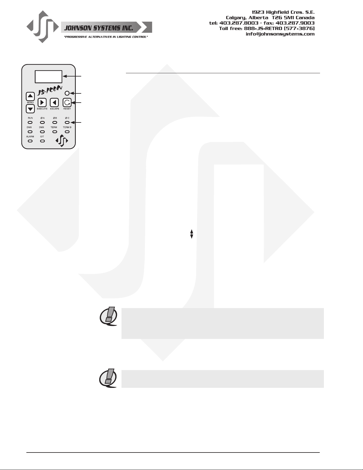
LCD Display
Infrared LED
Programming
Switches
System
Status
LED Indicators
User Interface
The user interface provides access to all programming and conguration
settings. System status is easily visible on the LCD display and LED
indicators. All JS-ICON™ Series dimmer racks are equipped with a user
interface connected to the Signal Distribution Board via a 34-pin ribbon
cable.
An infrared LED allows for printout of all system conguration settings
when used with a hand held infrared printer (Johnson System Inc., Part
Number: JS-IP).
All of the programming is accomplished using four (4) switches. Within
a few minutes, most users will nd the menu structure very intuitive and
easy to navigate. All conguration settings are automatically stored into
E2ROM.
LCD Display
The LCD display is capable of displaying 2 lines of 8 Characters.
A backlight automatically comes on when activity is sensed on the
switches. The LCD contrast can be easily adjusted for optimum viewing.
Refer to menu item “LCD VIEW” on page 30 for further details.
Programming Switches
The MENU UP/DOWN ( ) switches are used for navigating through
the various system conguration menu items. They also allow for
programming of other specic parameters within a selected menu.
Pressing and holding either switch will speed up the scroll rate, which can
be helpful to speed up the conguration time.
The EXECUTE switch is normally used to select/enter a menu item,
advance forward within a selected menu item, or toggle between
parameters within a selected menu item.
The ESCAPE switch is normally used to back up within a selected menu
item one step at a time, or exit the menu completely.
NOTE: The programming switches can be locked out to prevent
inadvertent conguration changes. To toggle between “LOCKED!!” and
“UNLOCKED” press and hold down the EXECUTE and then ESCAPE
switches at the same time for 4-5 seconds.
The RESET switch has two purposes. First, it allows for quick exit from
a menu item after a programming change, and automatically puts the
system into normal run mode. Second, it provides a soft reboot for the
systems microcontroller.
NOTE: A detailed procedure for programming all system conguration
menu items can be found on page 15 to 30.
12
www.johnsonsystems.com
Page 13
System Status - LED Indicators
RUN (Green)
Illuminates when the power is on, and the microcontroller status is in normal run mode. The LED
ashes once every 2 seconds when the system is in STANDBY mode.
ØA, ØB and ØC (Green)
Illuminates when the line voltage power is within the acceptable range of 100-130 VAC for each
phase, and the zero-cross reference circuitry is functioning properly. The LED will ash slowly
(once per second) when an under-voltage state of less than 100 VAC is sensed, and will ash
quickly (twice per second) when an over-voltage of greater than 130 VAC is sensed.
DMX A and DMX B (Yellow)
Illuminates when valid DMX is received on each of the inputs. Flashes when invalid DMX is
received.
TERM A and TERM B (Yellow)
Illuminates when DMX is terminated on each of the inputs.
ALARM
Illuminates and ashes twice per second when either a re or security alarm is sensed on each of
the inputs.
O/T
Illuminates and ashes twice per second whenever one of three over-temperature sensing inputs
are triggered.
System Status - LCD Display
When DMX is being received, the top line of the LCD display shows the active DMX MODE (“PTY
A”, “PTY B”, “MERGE”, “DMX A+B”, “2 ROOM” or “PATCH”). When DMX is not being received,
the top line of the LCD display shows “MADD-24”, unless the system is in standby mode, then
“STANDBY!” is displayed.
The bottom line of the LCD Display shows the current status of the system, unless the system
conguration menu items are being accessed. Below are descriptions for each status indication.
NO RX!
Displayed when DMX is not being received on either input, and the system is not in scene mode.
AXXXBXXX
Displayed when valid DMX is being received on one or both inputs, and both inputs are not
terminated. “A” and “B” represent the DMX A and DMX B inputs, while “XXX” represents the
number of channels being received in each packet of data. For example, if the system is receiving
512 channels on DMX B and DMX A is disconnected, the display will show “A000B512”.
XXX
XXX
Same as above, except the “A” and “B” is replaced with “ ” to indicate if one or both of the DMX
inputs are terminated. For example, if the system is receiving 48 channels on DMX A and 512
channels on DMX B, with only DMX A terminated, the display will show “
menu items “DMXA TRM” and “DMXB TERM” on page 18 and 19 for further details.
SH XX:YY
Displayed when DMX is disconnected, and the systems predetermined DMX status hold (SH)
time is counting down. “XX” represents minutes, while “YY” represents seconds. Refer to menu
item “SH TIME” on page 21 for further details.
048B512”. Refer to
www.johnsonsystems.com 13
Page 14

INF HOLD
Displayed when DMX is disconnected, and the systems predetermined DMX status hold (SH)
time is set for innite (INF) hold. Refer to menu item “SH TIME” on page 21 for further details.
SCENE:XX
Displays the scene (1 to 24) that is currently activated. Refer to menu item “L-BUTTON” on page
24 for further details.
A-SCENE!
Displayed when the auxiliary input is triggered. Refer to menu item “AUX IN” on page 24 for
further details.
FIRE!!!
Displayed when the re alarm input is triggered. Refer to menu item “F-ALARM” on page 25 for
further details.
SECURITY
Displayed when the security alarm input is triggered. Refer to menu item “S-ALARM” on page 24
for further details.
EXT-TEMP
Displayed when the external over-temperature (O/T) input is triggered, or when the systems
thermostat senses an over-temperature condition between 185°F (85°C) and 203°F (95°C).
All dimmer outputs are disabled and the fans are turned on to full, until the external devices
temperature drops to within specication.
REM-TEMP
Displayed when the systems remote temperature sensor measures an over-temperature
condition of 185°F (85°C) or more. All dimmer outputs are disabled and the fans are turned on to
full, until the temperature cools down to 178°F (81°C) or less. Refer to menu item “REM TEMP”
on page 26 to view the current remote temperature.
CTL-TEMP
Displayed when the microcontroller senses an internal over-temperature condition of 185°F
(85°C) or more. All dimmer outputs are disabled and the fans are turned on to full, until the
temperature cools down to 178°F (81°C) or less. Refer to menu item “CTL TEMP” on page 26 to
view the current microcontroller temperature.
Ø ERROR!
Displayed when an error is sensed on any of the input power phases. A phase error can be
caused from an under-voltage of less than 100VAC, an over-voltage of greater than 130VAC, or if
a zero-cross phase reference is not detected.
RTC ERR!
Displayed when the system detects a runtime counter (RTC) error. This occurs when there is an
invalid hard-key code, and the runtime counter is greater than 2160 hours (90 days). Refer to
menu item “HARD-KEY” on page 27 for further details.
LOCKED!!
Displayed when an attempt is made to access the system conguration menu items, and the
programming switches are locked out. To toggle between “LOCKED!!” and “UNLOCKED” press
and hold down the “EXECUTE” and then “ESCAPE” switches at the same time for 4-5 seconds.
Also displayed when an attempt is made to access factory only setup menus.
14
www.johnsonsystems.com
Page 15

Quick Programming Reference to System Configuration Menu Items
1. SCENESET Enable and setup 24 different backup scenes.
2. FADETIME Set the fade time for each of the 24 scenes from 0 to 99 seconds.
3. SNAPSHOT Record DMX levels into the backup scenes.
4. DIM TEST Test the dimmer outputs one at a time, or all at once.
5. MONITOR View the control level to each dimmer output.
6. ADDRESS Set the DMX start address.
7. DMX MODE Congure the mode of the on-board DMX protocol manager.
8. 2 RM SET Set the two room assignment for each of the dimmer outputs.
9. DMXA TRM Enable or disable termination on the DMX A input.
10. DMXB TRM Enable or disable termination on the DMX B input.
11. DMX O/P Congure the on-board DMX protocol manager for offset or patch mode.
12. DMXA PAT Patch the 24 dimmer (PWM) outputs to any DMX A input channel.
13. DMXB PAT Patch the 24 dimmer (PWM) outputs to any DMX B input channel.
14. SH TIME Set the DMX status hold time from 0 to 99 minutes or innite.
15. DC PATCH Congure the dimmer to channel patch for the dimmer rack.
16. DIM CURV Congure the dimmer curve for each output.
17. VOUT LIM Set the maximum RMS output voltage for each dimmer.
18. REGULATE Enable or disable the dimmer output voltage regulation.
19. ANA MODE Congure the analog inputs for normal or load shed mode.
20. ANA PTCH Patch the analog inputs to any combination of control channels.
21. ANA TEST View the control level for each of the analog inputs.
22. ANA FLTR Apply a noise lter on the analog inputs of up to 1 Volt.
23. ANA BLOC Enable or disable the analog inputs when DMX is being received.
24. STANDBY Enable or disable the power savings standby mode.
25. TEST INC Set the test increment units to percent or hexadecimal.
26. OC MODE Congure the input trigger parameters for the open collector output.
27. AUX IN Select which scene the auxiliary input will trigger/enable.
28. L-BUTTON Set the mode of the local buttons to scene, bump or disabled.
29. S-ALARM Select the level and control channels triggered by the security alarm input.
30. F-ALARM Select the level and control channels triggered by the re alarm input.
31. Ø-PATCH Set the zero-cross phase reference for each dimmer control output circuit.
32. WARMING Turn the “lamp warming” feature on or off.
33. POLARITY Set the PWM output control polarity. Locked for factory use only!
34. LINE V View the RMS line voltage for each power phase.
35. LINE F View the line frequency of phase A.
36. REM TEMP View the temperature of the remote temperature sensor.
37. CTL TEMP View the temperature of the microcontroller.
38. RTIME View the total run time of the microcontroller.
39. HARD-KEY View the microcontroller’s unique six-character hard-key code.
40. SERIAL# View the microcontroller’s unique six-character silicone serial number.
41. VERSION View the microcontroller’s rmware version.
42. EEPROM View the type of EEPROM memory module plugged in.
43. FW-LOAD Load new rmware into the MADD-24 via the EEPROM memory module.
44. RESTORE Restore parameters saved in the EEPROM memory module.
45. BACKUP Backup parameters and save them in the EEPROM memory module.
46. PRINTOUT Print various system conguration settings using a hand held infrared printer.
47. DEFAULTS Set various system conguration settings to the factory default.
48. LCD VIEW Adjust the contrast of the LCD Display for optimum viewing.
www.johnsonsystems.com 15
Page 16
Detailed Programming of System Configuration Menu Items
NOTE: The programming switches can be locked out to prevent inadvertent conguration
changes. To toggle between “LOCKED!!” and “UNLOCKED” press and hold down the EXECUTE
and then ESCAPE switches at the same time for 4-5 seconds.
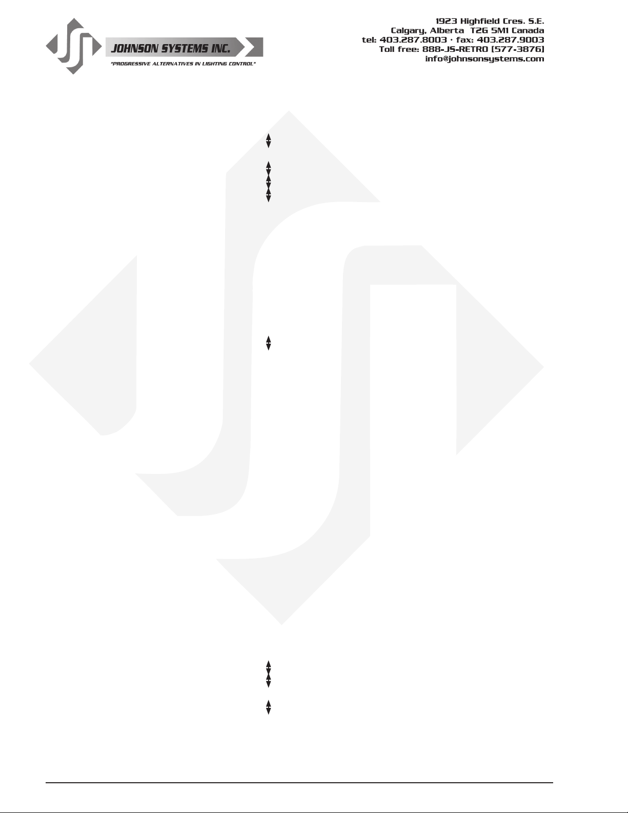
The sequence of the following system conguration menu items appear as the MENU DOWN ( ) switch
is pressed. Pressing the MENU UP ( ) switch will sequence the system conguration menu items in the
opposite order. Pressing and holding either of the MENU UP/DOWN ( ) switches will speed up the scroll
rate, which can be helpful to speed up the conguration time.
1. SCENESET Enable and setup 24 different backup scenes.
When scene mode is activated the selected scene will be held with no timeout until
the menu is exited. The 24 control channel levels are congured within the menu and
can be modied on the y. Scene mode is useful when an external controller is not
available and independent internal control is required.
Press EXECUTE to enter the menu and activate scene mode.
SCENE>01 Displays the scene (01) to be activated.
SCENE>24 Press MENU ( ) to select a different scene from 01 to 24.
CTRL: ON Control (CTRL) is ON via the selected scene.
CTRL:DMX Control (CTRL) is via DMX and takes priority over scene mode.
CTRL:HLD Control (CTRL) is via DMX status hold (HLD) and takes priority over scene mode.
SCENE>24 Press EXECUTE to activate the selected scene.
SCENE:24 The colon (:) ashes twice per second while fading to the selected scene.
SCENE:24 The colon (:) stops ashing when fade is complete and the selected scene is active.
SCENE>24 Press MENU ( ) to select a different scene from 01 to 24.
SCENE 24 Press EXECUTE to modify the selected scene.
C>01L 00 The second line on the LCD indicates the control channel (C) and level (L).
C>24L 00 Press MENU ( ) to select the control channel (C) to modify from 01 to 24.
C 24L>00 Press EXECUTE to toggle from channel (C>) to level (L>) selection.
C>24L 00 Press ESCAPE to toggle from level (L>) to channel (C>) selection.
C24L>FL Press MENU ( ) to select the output level (L) for the selected channel from 00 to FL.
CLEAR??? Press EXECUTE to clear the selected preset, and set all channels to 00 level.
SURE ??? Press EXECUTE if you are sure to clear the selected preset.
DONE !!! Indicates the selected preset has been cleared.
WAIT... Press ESCAPE to exit and the menu and save programmed scene levels.
Press ESCAPE to back-up within the menu, or exit/deactivate scene mode.
Press RESET to exit scene mode without saving programmed scene levels.
NOTE: When scene mode is activated: DMX and DMX status hold (SH TIME)
automatically takes precedence over scene mode. The analog input levels are
merged (HTP) with the scene levels. If the analog inputs are congured for load
shed mode the inputs will take precedence over the active scene. The security
alarm (S-ALARM) input is merged (HTP) with the scene levels while the re alarm
(F-ALARM) input automatically takes precedence. The local buttons (L-BUTTONS)
are temporarily set for scene mode and the auxiliary input (AUX IN) is enabled.
Scene mode will only activate dimmers assigned to room “A”.
16
2. FADETIME Set the fade time for each of the 24 scenes from 0 to 99 seconds.
The factory default is 5 seconds for all 24 presets.
Press EXECUTE to enter the menu.
S>01T 05 Displays the scene (S>01) and assigned fade time (T 05).
S>24T 05 Press MENU ( ) to select a different scene from 01 to 24.
S 24T>05 Press EXECUTE to toggle between scene (S>) and fade time (T>) selection.
S 24T>99 Press MENU ( ) to select a different fade time from 00 to 99 seconds.
Press ESCAPE to exit the menu and save the selected fade time.
Press RESET to exit the menu without saving.
The menu will automatically timeout after 2 minutes of inactivity and save.
www.johnsonsystems.com
Page 17
3. SNAPSHOT Record DMX levels into the backup scenes.
Provides a quick and easy way to save control channel levels into each of the
01 to 24 backup scenes using a DMX source.
Press EXECUTE to enter the menu and activate snapshot mode.
SAVE >01 Press MENU ( ) to select a different scene from 01 to 24.
SCENE>24 Press EXECUTE to store DMX levels in the selected scene.
SURE ??? Press EXECUTE if you are sure the DMX levels are set as intended.
DONE !!! DMX levels have now been stored in the selected scene.
NO RX! DMX is not being received on either input, so a snapshot is not possible.
Press ESCAPE to back-up within the menu, or exit/deactivate snapshot mode.
Press RESET to exit/deactivate snapshot mode.
4. DIM TEST Test the dimmer outputs one at a time, or all at once.
A technician’s best friend! Used for troubleshooting the dimmer outputs and eld
wiring to the load.
Press EXECUTE to enter the menu and activate dimmer test mode.
D 01L>00 Displays the active dimmer (D) and the test level (L).
D 01L>50 Press MENU ( ) to select the desired test level.
D 01L>FL Press ESCAPE to toggle the test level from full-on (FL) and off (00).
D>01L FL Press EXECUTE to toggle between the dimmer (D>) and the test level (L>).
D>ALL FL Press MENU ( ) to select the active dimmer from 01 to 24 or ALL.
Press ESCAPE or RESET to exit the menu.
The menu will automatically timeout after 2 minutes of inactivity.
5. MONITOR View the control level to each dimmer output.
The dimmer control level is displayed as a 9-bit value from 000 to 512. This menu
does not timeout automatically and will continue to monitor indenitely.
Press EXECUTE to enter the menu and activate monitor mode.
D>01L000 Press MENU ( ) to select the dimmer (D) output to monitor from 01 to 96.
D>24L512 Display shows dimmer 24 has full-on control.
Press ESCAPE or RESET to exit the menu.
NOTE: The control value will not reach 512 when voltage output limiting is activated,
or when regulation is enabled and the line voltage is greater than 118 VAC.
6. ADDRESS Set the DMX start address.
The DMX start address can be assigned from 001 to 512, and is common to both
DMX inputs. When DMX MODE is set for DMX A+B operation, each of the DMX
inputs can be assigned to a separate DMX start address. The DMX inputs are merged
and DMX-B is offset by the number of DMX-A channels.
Press EXECUTE to enter the menu.
DMXA>001 Displays the current DMX start address for both DMX inputs.
DMXA>512 Press MENU ( ) to modify and select the desired DMX start address.
DMXA>001
DMXA>025 Press EXECUTE to save the selected DMX start address.
DMXB>001 * Press EXECUTE to advance to select the DMX-B start address.
DMXB>512 *
#CHA=>01 * Press EXECUTE to advance to select the number of DMX-A channels.
#CHA=>24 *
Press RESET to exit the menu without saving.
NOTE: * DMX MODE must be set for DMX A+B operation to access this feature.
NOTE: DMX O/P must be set to OFFSET mode for this menu to function.
Press both MENU ( ) simultaneously to toggle to DMX start address 001.
Press MENU ( ) to modify and select the desired DMX start address.
Press MENU ( ) to modify the number of DMX-A channels from 01 to 24.
Press ESCAPE to exit the menu and save the selected DMX start address.
The menu will automatically timeout after 2 minutes of inactivity and save.
www.johnsonsystems.com 17
Page 18
7. DMX MODE Congure the mode of the on-board DMX protocol manager.
There are ve different mode settings for the DMX protocol manager.
Priority A (PTY A) and Priority B (PTY B) modes are intended for the implementation of a
backup DMX source. Priority A (PTY A) sets the DMX A input as the priority, and ignores the
DMX B input when the DMX A input is active. Priority B (PTY B) sets the DMX B input as
the priority, and ignores the DMX A input when the DMX B input is active.
Merge (MERGE) mode combines both DMX inputs with highest-takes-precedence (HTP)
operation. Merge mode allows for simultaneous DMX control of the dimmers from both
inputs, and is the default for the system.
Dual Universe DMX (DMX A+B) mode provides a method to combine two universes of
DMX within one system. It permits two independent DMX sources to be active on the DMX
inputs, with each having a separate DMX start address. The DMX inputs are merged and
DMX-B is offset by the number of DMX-A channels programmed via the ADDRESS menu
(see page 17 for further details). This feature is typically used when a system is at the end
of one DMX universe (DMX-A) and the beginning of another (DMX-B).
Two Room (2 ROOM) mode enables the room (A or B) assignment for each of the dimmer
outputs via the 2 RM SET menu.
PTY A Press EXECUTE to toggle into Priority A (PTY A) mode.
PTY B Press EXECUTE to toggle into Priority B (PTY B) mode.
MERGE Press EXECUTE to toggle into Merge (MERGE) mode.
DMX A+B Press EXECUTE to toggle into Dual Universe DMX (DMX A+B) mode.
2 ROOM Press EXECUTE to toggle into Two Room (2 ROOM) mode.
Press ESCAPE or RESET to exit the menu.
Any change in the conguration is automatically saved.
NOTE: DMX O/P must be set to OFFSET mode for this menu to function.
8. 2 RM SET Set the two room assignment for each of the dimmer outputs.
This menu is used to assign each of the 24 dimmer outputs to room “A” or room “B”.
Dimmer outputs assigned to room “A” are controlled via the DMX-A input. Dimmer outputs
assigned to room “B” are controlled via the DMX-B input. This creates separation within
the dimmer rack and makes a single dimmer rack function as though it is two independent
dimmer racks. When used in conjunction with the DC PATCH menu, the dimmer rack
can be congured for sequential DMX control of two rooms, even if the dimmer room
assignments are not sequential.
DMX MODE must be set for 2 ROOM operation for this menu to function.
Press EXECUTE to enter the menu and activate 2 RM SET mode.
DIM 01 A Displays the dimmer (DIM) output (01) and the room assignment (A).
DIM 24 A Press MENU ( ) to select a different dimmer output from 01 to 24.
DIM 24 B Press EXECUTE to toggle the room assignment from A to B.
Press ESCAPE or RESET to exit the menu.
Any change in the conguration is automatically saved.
NOTE:
NOTE: DMX O/P must be set to OFFSET mode for this menu to function.
Scene mode (SCENESET) will only activate/control dimmers assigned to room “A”.
.
9. DMXA TRM Enable or disable termination on the DMX A input.
Activates and deactivates a 120Ω termination resistor. DMX termination is indicated on
the LCD display when DMX is being received. When the DMX A input is not terminated
(DISABLED) the LCD display will read AXXXBXXX. When the DMX A input is teminated
(ENABLED) the LCD display will read
T
XXXBXXX.
M
ENABLED Press EXECUTE to toggle termination from ENABLED to DISABLED.
DISABLED Press EXECUTE to toggle termination from DISABLED to ENABLED.
Any change in the conguration is automatically saved.
18
NOTE: Ensure only the last (end-of-line) DMX receiving device is terminated!
www.johnsonsystems.com
Page 19
10. DMXB TRM Enable or disable termination on the DMX B input.
Activates and deactivates a 120Ω termination resistor. DMX termination is indicated
on the LCD display when DMX is being received. When the DMX B input is not
terminated (DISABLED) the LCD display will read AXXXBXXX. When the DMX B
input is teminated (ENABLED) the LCD display will read AXXX
T
XXX.
M
ENABLED Press EXECUTE to toggle termination from ENABLED to DISABLED.
DISABLED Press EXECUTE to toggle termination from DISABLED to ENABLED.
Any change in the conguration is automatically saved.
NOTE: Ensure only the last (end-of-line) DMX receiving device is terminated!
11. DMX O/P Congure the on-board DMX protocol manager for offset or patch mode..
OFFSET mode is typically used for the majority of systems, and is the factory default.
OFFSET mode refers to the DMX start address, with each of the 24 dimmer (PWM)
outputs addressed sequentially from the DMX start address.
PATCH mode provides full exibility for addressing each of the 24 dimmer (PWM)
outputs. Each of the 24 dimmer (PWM) outputs can be patched to (controlled from)
any DMX input channel from 001 to 512, from either or both of the DMX A and DMX B
inputs simultaneously
With DMX patch mode activated, any conguration within the ADDRESS, DMX
MODE, 2 RM SET and DC PATCH menus is ignored, and the DMX patch congured
within the DMXA PAT and DMXB PAT menus takes precedence.
When using the system in DMX patch mode, it is strongly recommended to printout
the patch using a hand held infrared printer (Johnson System Inc., Part Number: JS-IP).
Press EXECUTE to enter the menu and congure the DMX mode.
DISABLED This menu is disabled to help prevent inadvertent changes. Proceed to enable.
ENABLED Press and hold MENU ( ) and MENU ( ) at the same time for 4-5 seconds.
OFFSET Press EXECUTE to toggle the DMX mode from OFFSET to PATCH.
PATCH Press EXECUTE to toggle the DMX mode from PATCH to OFFSET.
Press ESCAPE or RESET to exit the menu.
Any change in the conguration is automatically saved.
12. DMXA PAT Patch the 24 dimmer (PWM) outputs to any DMX A input channel.
There are two ways to congure the DMX patch. Each of the 24 dimmer (PWM)
outputs can be manually (MANUAL) patched to a DMX input channel, or patched in
blocks (BLOCK) of sequential dimmers and DMX channels.
For MANUAL patching, each of the dimmers are patched individually. First, the
dimmer (DIM) output is selected, and then any DMX input channel from 001 to 512 is
patched to the selected dimmer.
For BLOCK patching, a sequential range of dimmers are patched to a sequential
range of DMX channels. First, the rst dimmer number (DIM#) in the block is selected,
then the DMX A start address (DMXA) for the block is selected, and then nally the
number of dimmers (#DIM) in the block is selected. For example, if DIM# is 001, DMX
is 001, and #DIM is 024, then all of the dimmer outputs, 001 thru 024 are addressed
sequentially to DMX channels 001 thru 024.
For a more complex example, if DIM# is 007, DMX is 321, and #DIM is 012, then
dimmer outputs 007 thru 018 are addressed sequentially to DMX channels 321 thru 344.
Using a combination of MANUAL and BLOCK patching methods can speed up
conguration. Typically, a BLOCK of dimmers is rst patched and then edited using
the MANUAL patch.
The DMX patch should be cleared (CLEAR) before conguring the patch. Clearing
the patch ensures all previously congured patch data is cleared (erased).
When DMXA PAT is utilized in conjunction with DMXB PAT, each of the 24 dimmer
(PWM) outputs can be patched to (controlled from) any DMX input channel from 001
to 512, from either or both of the DMX A and DMX B inputs simultaneously.
www.johnsonsystems.com 19
Page 20
If a dimmer is patched to both DMX A and DMX B input channels, the DMX levels are
merged and highest-takes-precedence (HTP).
Press EXECUTE to enter the menu and congure the DMX A patch.
Press MENU ( ) to scroll through and select the patching method.
MANUAL? Press EXECUTE to patch each of the dimmers manually (MANUAL).
DIM DMXA The top line shows the dimmer (DIM) and (DMXA) address headings.
001<999? The second line shows the dimmer (DIM) and (DMXA) address values.
024<999? Press MENU ( ) to select the dimmer (DIM) from 001 to 024 to patch.
001<999? Press MENU ( ) and MENU ( ) at the same time to toggle back to 001.
001 999? Press EXECUTE to advance and select the DMXA address for the dimmer.
001 999? DMXA is initialized at 999 to indicate the dimmer is not patched.
001 999? ? indicates the DMXA address (513 to 999) is invalid and is not patched.
001 999? The cursor (_) position indicates the DMXA digit to be edited.
001 999? Press EXECUTE to move the cursor to the right, under the digit to be edited.
001 999? Press ESCAPE to move the cursor to the left or to exit the menu.
001 512 Press MENU ( ) to select the DMXA address from 001 to 512.
001 999? Press MENU ( ) and MENU ( ) at the same time to toggle back to 999.
Repeat until all required dimmers are manually patched.
BLOCK? Press EXECUTE to patch the dimmers in a sequential block (BLOCK).
DIM#:001 Press EXECUTE to select the rst dimmer number (DIM#) in the block.
DIM#:024 Press MENU ( ) to edit the dimmer number (DIM#) from 001 to 024.
DIM#:001 Press MENU ( ) and MENU ( ) at the same time to toggle back to 001.
DMXA:001 Press EXECUTE to select the DMX A (DMXA) start address for the block.
DMXA:512 Press MENU ( ) to edit the DMX A (DMXA) start address from 001 to 512.
DMXA:001 Press MENU ( ) and MENU ( ) at the same time to toggle back to 001.
#DIM:001 Press EXECUTE to select the number of dimmers (#DIM) in the block.
#DIM:024 Press MENU ( ) to edit the number of dimmers (#DIM) from 001 to 024.
#DIM:001 Press MENU ( ) and MENU ( ) at the same time to toggle back to 001.
PROCEED? Press EXECUTE to proceed.
SURE ??? Press EXECUTE to proceed.
DONE !!! Indicates the sequential block patch has been completed.
Repeat until all required blocks of sequential dimmers have been patched.
Press ESCAPE to exit the menu.
CLEAR??? Press EXECUTE to clear the entire patch.
SURE ??? Press EXECUTE to proceed.
DONE !!! Indicates the entire patch has been cleared.
Press ESCAPE to exit the menu and save the selected patch.
Press RESET to exit the menu without saving.
The menu will automatically timeout after 5 minutes of inactivity and save.
NOTE: Be sure to BACKUP any conguration changes!
20
NOTE: With DMX patch mode activated, any conguration within the ADDRESS,
DMX MODE, 2 RM SET and DC PATCH menus is ignored, and the DMX patch
congured within this menu takes precedence.
13. DMXB PAT Patch the 24 dimmer (PWM) outputs to any DMX B input channel.
Refer to the DMXA PAT menu for further information.
The DMXA PAT menu is used to patch dimmers to DMX A input channels, while the
DMXB PAT menu is used to patch dimmers to DMX B input channels.
www.johnsonsystems.com
Page 21
14. SH TIME Set the DMX status hold time from 0 to 99 minutes or innite.
When DMX is disconnected the system will hold the status of the last received DMX
levels for the selected amount of time. When activated, the LCD display shows a
countdown of the status hold time or innite hold.
Press EXECUTE to enter the menu.
HTIME 00 Displays the current DMX status hold time (HTIME) setting.
HTIME 99 Press MENU ( ) to set the desired hold time from 00 to 99 minutes.
HTIME XX Press MENU ( ) to set the desired hold time to innite (XX).
HTIME 00 Press both MENU ( ) switches to toggle back to status hold time of 00.
Press ESCAPE to exit the menu and save the desired DMX status hold time.
Press RESET to exit the menu without saving.
The menu will automatically timeout after 2 minutes of inactivity and save.
15. DC PATCH Congure the dimmer to channel patch for the dimmer rack.
Each of the 96 dimmer (PWM) outputs can be assigned and patched to any of the 96
control channels. Multiple dimmer outputs may be patched to a single control channel.
The dimmer to channel patch is used by other menu features to provide transparent
control of the dimmer output circuits. JS-ICON™ Series dimmer racks are typically
patched for 1 to 1 operation but may be altered for custom applications.
Press EXECUTE to enter the menu.
D01<C01 Displays the dimmer (D) output (01) and its current control channel (C) patch (01).
D24<C24 Press MENU ( ) to select the desired dimmer output from 01 to 24.
D24 C24< Press EXECUTE to toggle the pointer (<) to select the control channel to patch.
D24 C01< Press MENU ( ) to select the desired control channel from 01 to 24.
D24<C01 Press EXECUTE to toggle the pointer (<) to select another dimmer output.
Press ESCAPE to exit the menu and save the desired dimmer channel patch.
Press RESET to exit the menu without saving.
The menu will automatically timeout after 2 minutes of inactivity and save.
NOTE: DMX O/P must be set to OFFSET mode for this menu to function.
16. DIM CURV Congure the dimmer curve for each output.
There are four different dimmer curve proles that can be assigned to each individual
dimmer output circuit. Square Law (SQ) curve is the industry standard and the default
for all dimmers. Linear (LN) curve modies the dimmer output for a linear relationship
to the control input level. Direct Drive (DD) curve is not modied - meaning the control
input level is directly proportional to the control output level. Non-Dim (ND) curve
assigns the dimmer circuit to operate in a full-on or off state only, with no dimming.
Dimmers set for non-dim will be triggered full-on at 55% control input and will be
triggered off again at 45% control input.
Press EXECUTE to enter the menu.
DIM01 SQ Displays the dimmer (DIM) output (01) and its current dimmer curve.
DIM24 SQ Press MENU ( ) to select the desired dimmer number from 01 to 24.
DIM24 LN Press EXECUTE to toggle to linear (LN) curve mode.
DIM24 DD Press EXECUTE to toggle to direct drive (DD) mode.
DIM24 ND Press EXECUTE to toggle to non-dim (ND) mode.
Press ESCAPE to exit the menu and save the desired dimmer curves.
Press RESET to exit the menu without saving.
The menu will automatically timeout after 2 minutes of inactivity and save.
www.johnsonsystems.com 21
Page 22
17. VOUT LIM Set the maximum RMS output voltage for each dimmer.
Limiting the maximum RMS voltage can greatly improve lamp life.
Press EXECUTE to enter the menu.
01<127.5 Displays the dimmer (01) and its current maximum output voltage level (127.5).
24<127.5 Press MENU ( ) to select the desired dimmer number from 01 to 24.
24>127.5 Press EXECUTE to toggle the pointer (< >) to select the output voltage level.
24>100.0 Press MENU ( ) to adjust the output voltage level in 0.5 Volt increments.
24<100.0 Press EXECUTE to toggle the pointer (< >) to select another dimmer number.
Press ESCAPE to exit the menu and save the desired dimmer curves.
Press RESET to exit the menu without saving.
The menu will automatically timeout after 2 minutes of inactivity and save.
18. REGULATE Enable or disable the dimmer output voltage regulation.
With the on-board output voltage regulation feature enabled the maximum RMS
output is limited to 118 Volts. Voltage regulation automatically adjusts the internal
control level to compensate for any line voltage uctuations.
ENABLED Press EXECUTE to toggle regulation from ENABLED to DISABLED.
DISABLED Press EXECUTE to toggle regulation from DISABLED to ENABLED.
Any change in the conguration is automatically saved.
19. ANA MODE Congure the analog inputs for normal or load shed mode.
Each of the four (4) analog inputs can be independently congured for normal
(NORM) or load shed (SHED) mode of operation.
Normal (NORM) mode sets the analog input for 0-10VDC operation. The analog
voltage level sensed sets the level for the selected dimmer outputs.
Load shed (SHED) mode is used as a power management interface to building
management systems (BMS). Contact closure devices such as a photocell or
maintained switch contact may be used to trigger the analog input. When a voltage
of 5.5VDC to 12VDC is sensed on the analog input the selected dimmer outputs are
disabled (set to zero output level). The selected dimmer outputs are enabled when
the voltage sensed on the analog input drops to below 4.5VDC.
Press EXECUTE to enter the menu and set the mode for each analog input.
A01<NORM Displays the active analog input (A01) and current mode setting (NORM).
A04<NORM Press MENU ( ) to select the desired analog input to congure from 01 to 04.
A04<SHED Press EXECUTE to toggle from normal (NORM) to load shed (SHED) mode.
Press ESCAPE to exit the menu and save the desired analog input modes.
Press RESET to exit the menu without saving.
The menu will automatically timeout after 2 minutes of inactivity and save.
22
20. ANA PTCH Patch the analog inputs to any combination of control channels.
Press EXECUTE to enter the menu and activate analog patch mode.
A01<C01 Displays the active analog input (A01) and control channel (C01).
A04<C01 Press MENU ( ) to select the desired analog input to patch.
A04>C01 Press EXECUTE to toggle the pointer (>) to select the control channel.
A04>C24 Press MENU ( ) to select the desired control channel from 01 to 24.
A04>C24 * Press EXECUTE to patch and ag (*) the control channel to the analog input.
A04<C24 * Press ESCAPE to toggle the pointer (< >) to select another analog input.
Press ESCAPE to exit the menu and save the desired analog patches.
Press RESET to exit the menu without saving.
The menu will automatically timeout after 2 minutes of inactivity and save.
www.johnsonsystems.com
Page 23

21. ANA TEST View the control level for each of the analog inputs.
The analog voltage level for the 4 analog inputs can be tested and viewed as a
percentage or hexadecimal value. The level displayed is proportional to the 0-10VDC
analog input where 5VDC is 50%.
Press EXECUTE to enter the menu and activate analog test mode.
AI>01=00 Displays the active analog input (AI>01) and the level (00).
AI>04=00 Press MENU ( ) to select the desired analog input to test.
AI>04=FL Displays the analog input level from off (00) to full-on (FL).
Press ESCAPE or RESET to exit the menu.
22. ANA FLTR Apply a noise lter on the analog inputs of up to 1 Volt.
High frequency noise can sometimes be induced into the analog input lines. The
analog lter is set in 1% increments where each percent (%) represents 0.1 Volts for
a maximum lter level of 1 Volt, or 10%. For example, when the analog lter level is
set at 5% (LEV:05%) all analog input levels at or below 0.5 Volts is ignored or ltered out.
LEV:00% Displays the lter level (00%) in percent.
LEV:00%< Press EXECUTE to enter the menu and adjust the analog lter level.
LEV:10%< Press MENU ( ) to select the desired lter level.
Press ESCAPE to exit the menu and save the desired analog lter level.
Press RESET to exit the menu without saving.
The menu will automatically timeout after 2 minutes of inactivity and save.
23. ANA BLOC Enable or disable the analog inputs when DMX is being received.
When analog blocking (ANA BLOC) is enabled the analog inputs will be ignored when
DMX is online. When analog blocking is disabled the analog inputs will be merged/
combined with the DMX inputs and functions in a highest-takes-precedence (HTP)
mode of operation.
ENABLED Press EXECUTE to toggle analog blocking from ENABLED to DISABLED.
DISABLED Press EXECUTE to toggle analog blocking from DISABLED to ENABLED.
Any change in the conguration is automatically saved.
24. STANDBY Enable or disable the power savings standby mode.
When standby mode is enabled the microcontroller goes to sleep within 5 seconds
of inactivity on the control inputs. The microcontroller wakes up again when a
programming switch is pressed or when control is sensed on the control inputs. Note
that there is a delay of 150 milliseconds for the microcontroller to wake up and restart
normal run mode.
ENABLED Press EXECUTE to toggle standby mode from ENABLED to DISABLED.
DISABLED Press EXECUTE to toggle standby mode from DISABLED to ENABLED.
Any change in the conguration is automatically saved.
25. TEST INC Set the test increment units to percent or hexadecimal.
The levels for the dimmer test (DIM TEST) and analog test (ANA TEST) features can
be displayed as a percentage or hexadecimal value.
PERCENT Press EXECUTE to toggle test increments from PERCENT to HEX VAL.
HEX VAL Press EXECUTE to toggle test increments from HEX VAL to PERCENT.
Any change in the conguration is automatically saved.
26. OC MODE Congure the input trigger parameters for the open collector output.
The on-board open collector output is used to sink up to 100mA of current. It can be
congured to be triggered via a selected DMX channel, analog input 4, or both. The
open collector is triggered on at 55% control input and triggered off again at 45%
control input. When analog and DMX (A+D) is selected to trigger the open collector
the inputs are combine for highest takes precedence (HTP).
Press EXECUTE to enter the menu and congure the open collector output.
www.johnsonsystems.com 23
Page 24
A+D< 001 Displays the active trigger mode as analog and DMX (A+D<) channel 001.
A+D> 001 Press EXECUTE to toggle the pointer (>) and select the DMX channel.
A+D> 512 Press MENU ( ) to change and select the DMX channel from 001 to 512.
A+D< 512 Press EXECUTE to toggle the pointer (<) and select a different trigger mode.
DMX< 512 Press MENU ( ) to select DMX input trigger mode.
ANA< Press MENU ( ) to select analog (ANA) input trigger mode.
OFF< Press MENU ( ) to deactivate (OFF) the open collector output.
Press ESCAPE to exit the menu and save the desired settings.
Press RESET to exit the menu without saving.
The menu will automatically timeout after 2 minutes of inactivity and save.
27. AUX IN Select which scene the auxiliary input will trigger/enable.
When a contact is sensed on the auxiliary input the selected scene will be triggered
and held until the contact is removed. The auxiliary input only functions when scene
mode (SCENESET) is activated or when the systems local buttons (L-BUTTONS) are
set for scene mode.
SCENE:01 Displays the scene (01) that will be triggered by the auxiliary input.
SCENE>01 Press EXECUTE to enter the menu and select a different scene.
SCENE>24 Press MENU ( ) to change the selected scene from 01 to 24.
Press ESCAPE to exit the menu and save the desired scene to be triggered.
Press RESET to exit the menu without saving.
The menu will automatically timeout after 2 minutes of inactivity and save.
28. L-BUTTON Set the mode of the local buttons to scene, bump or disabled.
JS-ICON™ Series dimmer racks normally have the local buttons disabled. Bump mode
is used in conjunction with 24 bump button switches, not applicable with JS-ICON™
Series dimmer racks.
Setting the local buttons to scene mode puts the system in scene mode. With scene
mode enabled, the selected scene will always be activated when DMX is not being
received. The selected scene can be changed in the SCENESET menu. Scene mode
enables the use of the auxiliary (AUX) input. A contact closure sensed on the over-
temperature (O/T), re alarm (FIRE) or security alarm (SCTY) input automatically
takes precedence over scene mode.
DISABLED Press EXECUTE to toggle the operation of the local buttons to disabled.
BUMP Press EXECUTE to toggle the operation of the local buttons to bump mode.
SCENE Press EXECUTE to toggle the operation of the local buttons to scene mode.
Any change in the conguration is automatically saved.
24
29. S-ALARM Select the level and control channels triggered by the security alarm input.
When a contact is sensed on the security alarm input, selected control channels will
cycle on and off at a 1 hertz rate. The level of the on cycle can be set from 0% to
100%. The security alarm input takes precedence over the DMX and analog inputs.
The system will stay in security alarm mode until the contact is removed.
Press EXECUTE to enter the menu and congure the security alarm input.
L>FL:01* Displays the output level (L>FL) of 100% and control channel (01*).
L>00:01* Press MENU ( ) to change the output level from 00% to 100% (FL).
L>FL:01* Press MENU ( ) at the same time to toggle the level back to 100% (FL).
L:FL>01* Press EXECUTE to toggle the pointer (>) and select the control channel(s).
L:FL>24* Press MENU ( ) to select the desired control channel from 01 to 24.
L:FL>24 Press EXECUTE to toggle the ag (*) for each desired control channel.
Press ESCAPE to exit the menu and save the desired settings.
Press RESET to exit the menu without saving.
The menu will automatically timeout after 2 minutes of inactivity and save.
www.johnsonsystems.com
Page 25
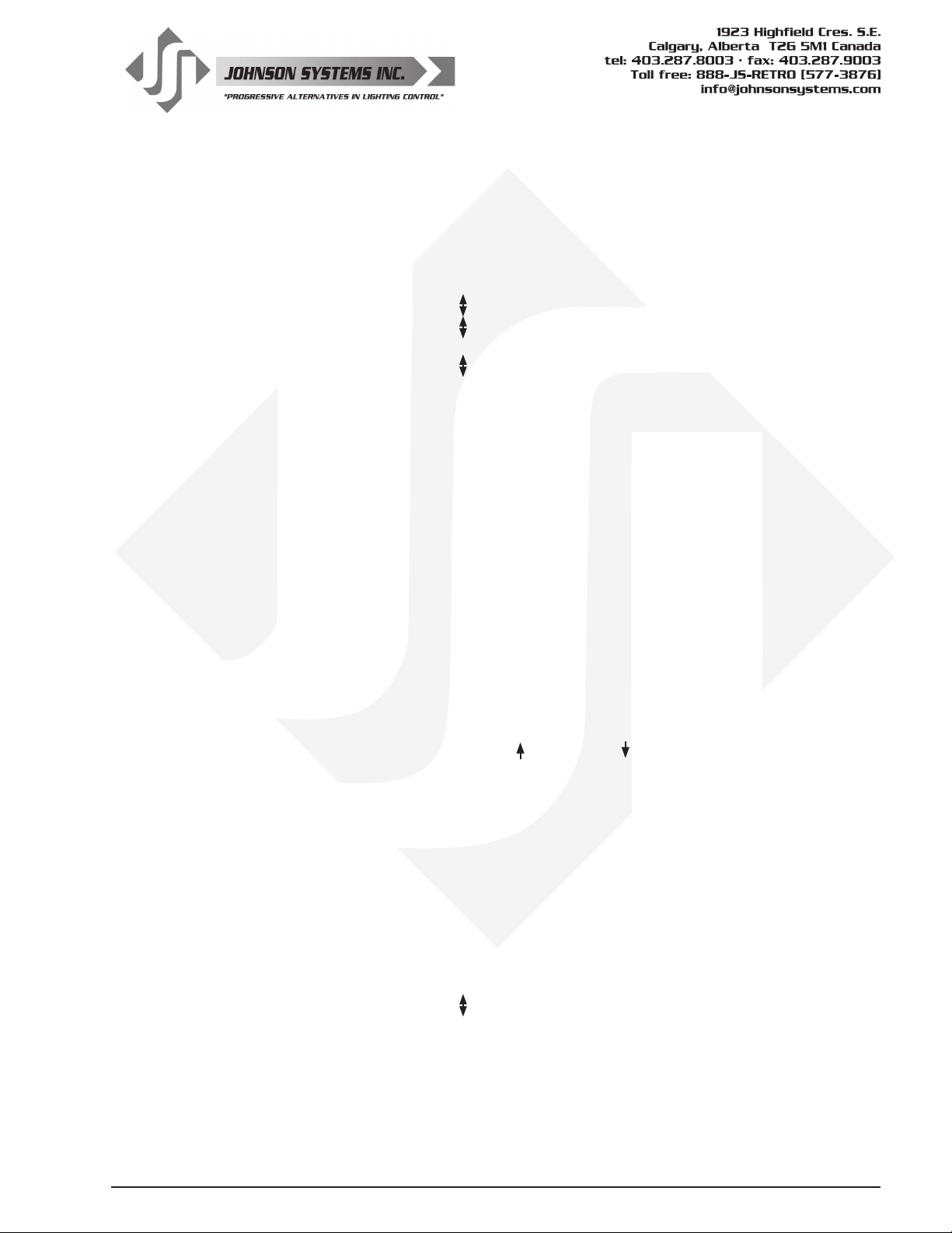
30. F-ALARM Select the level and control channels triggered by the re alarm input.
When a contact is sensed on the re alarm input, the selected control channels are
triggered on to the selected output level from 0% to 100%. The re alarm input is
merged with the DMX and analog inputs with highest takes precedence (HTP). The
system will stay in re alarm mode until the contact is removed.
Press EXECUTE to enter the menu and congure the re alarm input.
L>FL:01* Displays the output level (L>FL) of 100% and control channel (01*).
L>00:01* Press MENU ( ) to change the output level from 00% to 100% (FL).
L>FL:01* Press MENU ( ) at the same time to toggle the level back to 100% (FL).
L:FL>01* Press EXECUTE to toggle the pointer (>) and select the control channel(s).
L:FL>24* Press MENU ( ) to select the desired control channel from 01 to 24.
L:FL>24 Press EXECUTE to toggle the ag (*) for each desired control channel.
Press ESCAPE to exit the menu and save the desired settings.
Press RESET to exit the menu without saving.
The menu will automatically timeout after 2 minutes of inactivity and save.
31. WARMING Turn the “lamp warming” feature on or off.
WARMING is set to ON by factory default, but may be turned OFF for some
Press EXECUTE to enter the menu and congure the lamp warming mode.
DISABLED This menu is disabled to help prevent inadvertent changes. Proceed to enable.
ENABLED Press and hold MENU ( ) and MENU ( ) at the same time for 4-5 seconds.
ON Press EXECUTE to toggle the lamp warming mode from ON to OFF.
OFF Press EXECUTE to toggle the lamp warming mode from OFF to ON.
Press ESCAPE or RESET to exit the menu.
Any change in the conguration is automatically saved.
The unique “lamp warming” feature is activated by a control level above 0% and
lowers the in-rush current to the dimmer (cold lamp lament) by up to 70%. This
results in signicantly increased lamp lament life and lower long-term operating costs.
installation applications. With WARMING set to ON, a maximum delay of 245
milliseconds is introduced to “warm” the lamp when it is turned on. For fast chase
effects the delay may be undesirable, in which case, the “lamp warming” feature can
be turned off. Note that when standby mode is enabled the microcontroller goes to
sleep within 5 seconds of inactivity on the control inputs, and there is delay of 150
milliseconds for the microcontroller to wake up and restart normal run mode. To
ensure virtually instant dimmer control response, set STANDBY to DISABLED and
WARMING to OFF.
32. Ø-PATCH Set the zero-cross phase reference for each dimmer control output circuit.
The defaults (DEFAULTS) menu is normally used to congure the phase patch for
JS-ICON™ Series dimmer racks. This menu provides custom phase patching for non-
standard applications. If a dimmer control output is patched to the incorrect phase
reference, the dimmer will not dim correctly and will go to full output at around 1%
DMX input.
Press EXECUTE to enter the menu and congure the dimmer phase patch.
CH 01 ØA Displays the dimmer output channel (CH 01) and patched Phase A (ØA).
CH 24 ØA Press MENU ( ) to change the dimmer output channel to patch from 01 to 24.
CH 24 ØB Press EXECUTE to toggle the patch to Phase B (ØB).
CH 24 ØC Press EXECUTE to toggle the patch to Phase C (ØC).
Press ESCAPE to exit the menu and save the desired settings.
Press RESET to exit the menu without saving.
The menu will automatically timeout after 2 minutes of inactivity and save.
www.johnsonsystems.com 25
Page 26
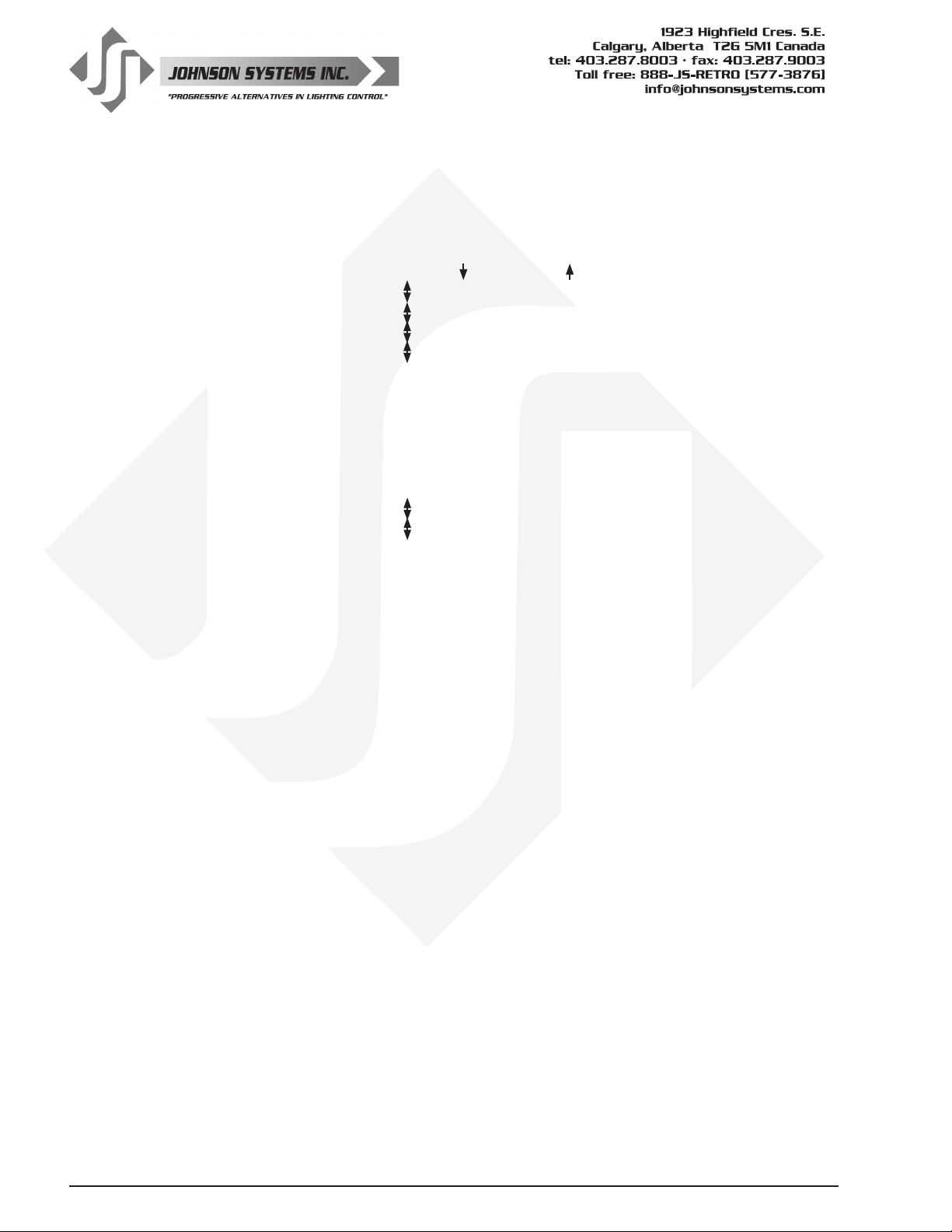
33. POLARITY Set the PWM output control polarity. Locked for factory use only!
This menu is only used when swapping the MADD-24 controller between different
models of JS-ICON™ Series dimmer racks.
Press EXECUTE to enter the menu and congure the polarity mode.
DISABLED This menu is for factory use, and is disabled for the end user.
ENABLED Press and hold MENU ( ) and MENU ( ) at the same time for 4-5 second.
MODE:1 Press MENU ( ) to select mode 1 - for JS-ICON™ 1220 operation.
MODE:2 Press MENU ( ) to select mode 2 - for JS-ICON™ 1210/620 operation.
MODE:3 Press MENU ( ) to select mode 3 (not applicable with JS-ICON™ product).
MODE:4 Press MENU ( ) to select mode 4 - for JS-ICON™ 2410 operation.
Press ESCAPE to exit the menu and save the desired settings.
Press RESET to exit the menu without saving.
The menu will automatically timeout after 2 minutes of inactivity and save.
34. LINE V View the RMS line voltage for each power phase.
Press EXECUTE to enter the menu and view the line voltage of each phase.
ØA=120.0 Shows the line voltage of Phase A.
ØB=120.0 Press MENU ( ) to view the line voltage of Phase B.
ØC=120.0 Press MENU ( ) to view the line voltage of Phase C.
Press ESCAPE or RESET to exit the menu.
35. LINE F View the line frequency of phase A.
60.0 Hz Shows the frequency.
36. REM TEMP View the temperature of the remote temperature sensor.
A thermostat measures the internal heat sink temperature.
+032°F Shows the temperature in degrees Fahrenheit.
+000°C Press EXECUTE to toggle units to degrees Celsius.
37. CTL TEMP View the temperature of the microcontroller.
+91°F Shows the temperature in degrees Fahrenheit.
+33°C Press EXECUTE to toggle units to degrees Celsius.
38. RTIME View the total run time of the microcontroller.
The run time counter keeps track of the total time the microcontroller is powered up.
The maximum time is 99999 hours, 59 minutes, 59 seconds, or about 11.4 years.
System operation is not effected when the maximum run time is reached and can be
reset to zero at the factory.
RTIME SS Shows the number of seconds (SS) of run time.
HHHHH:MM Shows the number of hours (HHHHH) and minutes (MM) of run time.
26
www.johnsonsystems.com
Page 27
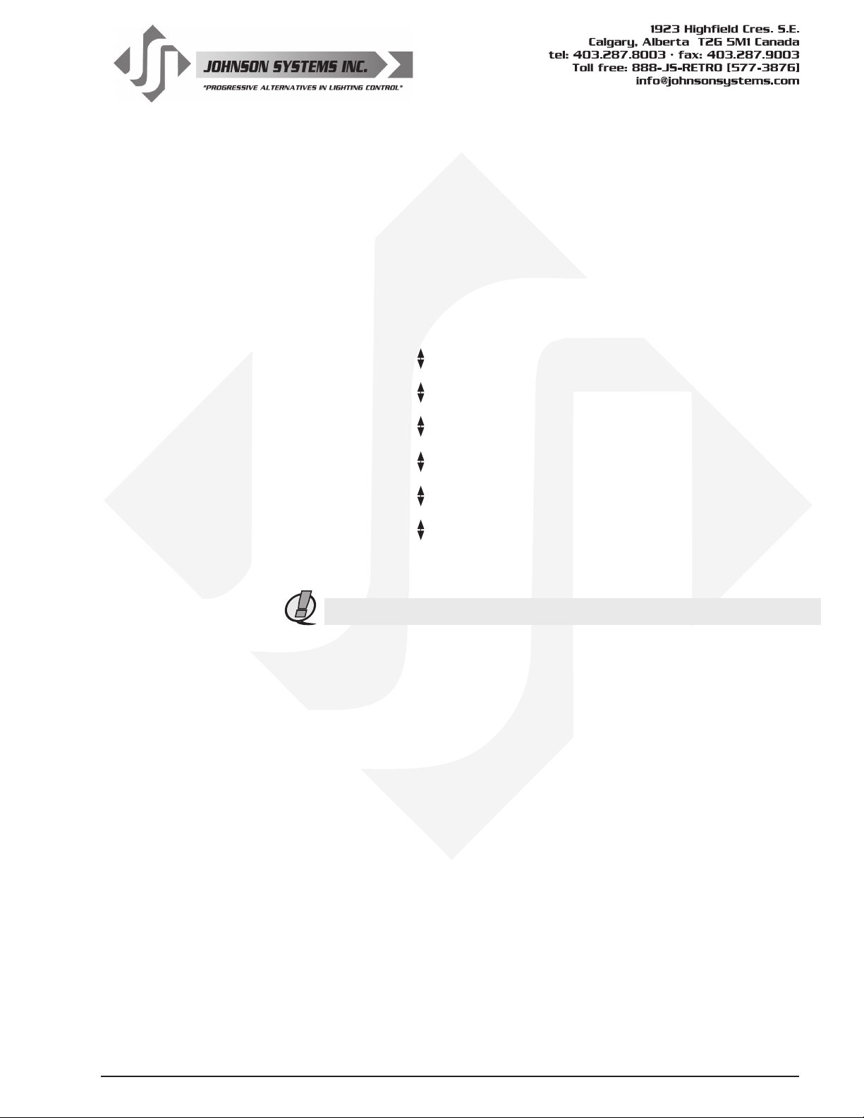
39. HARD-KEY View the microcontroller’s unique six-character hard-key code.
JS-ICON™ Series dimmer racks may be shipped with an invalid hard-key code of
000000. A valid hard-key must be entered before the run time (RTIME) counter
reaches 2160 hours / 90 days. If the run time expires without a valid hard-key the
LCD display will show a runtime counter error (RTC ERR!) and all dimmer control
outputs will be disabled.
HARD-KEY A dash (-) between hard and key represents a valid hard-key.
HARD KEY A blank space between hard and key represents an invalid hard-key.
K:XXXXXX Shows the unique six-character hard-key code (XXXXXX).
K:XXXXXX Follow the procedure below to enter the menu and modify the hard-key.
K:XXXXXX Press and hold EXECUTE and then ESCAPE at the same time for 4-5 seconds.
K>XXXXXX A pointer (>) appears to indicate hard-key modication is activated.
K>XXXXXX Press MENU ( ) to modify the rst hard-key character.
K:>XXXXX Press EXECUTE to advance to the second hard-key character.
K:>XXXXX Press MENU ( ) to modify the second hard-key character.
K:X>XXXX Press EXECUTE to advance to the third hard-key character.
K:X>XXXX Press MENU ( ) to modify the third hard-key character.
K:XX>XXX Press EXECUTE to advance to the fourth hard-key character.
K:XX>XXX Press MENU ( ) to modify the fourth hard-key character.
K:XXX>XX Press EXECUTE to advance to the fth hard-key character.
K:XXX>XX Press MENU ( ) to modify the fth hard-key character.
K:XXXX>X Press EXECUTE to advance to the sixth hard-key character.
K:XXXX>X Press MENU ( ) to modify the sixth hard-key character.
Press ESCAPE to exit the menu and save the desired hard-key code.
Press RESET to exit the menu without saving.
The menu will automatically timeout after 2 minutes of inactivity and save.
NOTE: Be sure to record and le the hard-key code on page 31 for future reference.
40. SERIAL# View the microcontroller’s unique six-character silicone serial number.
XXXXXX Shows the unique six-character serial number.
41. VERSION View the microcontroller’s software version.
VER X.X Shows the microcontroller’s software version.
42. EEPROM View the type of EEPROM memory module plugged in.
All JS-ICON™ Series dimmer racks come with a removable EEPROM memory module
located on the MADD-24 board. The EEPROM memory module inserts into the
PORT1 connector located on the upper center of the board, and may be removed for
safe storage.
The EEPROM type is programmed for parameter (P) or rmware (F) operation. A
parameter EEPROM is used to backup all of the current conguration settings. A
rmware EEPROM is used to update the current rmware version running on the
MADD-24 microcontroller to the rmware version saved on the EEPROM.
The EEPROM memory module supplied with all JS-ICON™ Series dimmer racks is
a parameter type with all of the factory default conguration settings saved onto it
before shipping.
MADD24-P Indicates the EEPROM memory module is for a MADD-24 microcontroller.
MADD24-P Indicates the EEPROM type is programmed for parameter (P) operation.
XXXXXX Press EXECUTE to display the silicone serial number parameter.
DISABLED Press EXECUTE and menu feature is disabled for factory use only.
MADD24-F Indicates the EEPROM type is programmed for rmware (F) operation.
VER X.X Press EXECUTE to display the version (VER) of the rmware.
DISABLED Press EXECUTE and menu feature is disabled for factory use only.
NONE! Indicates the EEPROM memory module is not installed.
www.johnsonsystems.com 27
Page 28
43. FW-LOAD Load new rmware into the MADD-24 via the EEPROM memory module.
If a rmware update is required, Johnson Systems Inc. may supply an EEPROM
memory module with the latest rmware version. The rmware EEPROM memory
module can be inserted into PORT1 on the MADD-24 board and the rmware can be
loaded into the microcontroller.
Press EXECUTE to enter the menu.
DISABLED This menu is disabled for inadvertent use. Proceed to enable.
ENABLED Press and hold MENU ( ) and MENU ( ) at the same time for 4-5 seconds.
MEMCHECK Automatically checks the EEPROM memory module for rmware type.
CRC-TEST Automatically does a CRC test on the rmware code in the EEPROM.
>>>>>>>> The CRC test in progress.
VER X.X Displays the rmware version on the EEPROM memory module.
UPDATE?? Press EXECUTE to proceed.
SURE ??? Press EXECUTE to proceed.
UPDATING Firmware update in progress.
WILL Firmware update in progress.
AUTO Firmware update in progress.
RESTART Firmware update in progress.
PLEASE Firmware update in progress.
WAIT.... When rmware update is complete the RUN LED ashes and system restarts.
NO MEM! Displayed if an EEPROM memory module is not detected.
WRONG Displayed if the wrong type (parameter) of EEPROM memory module detected.
MEM TYPE Displayed if the wrong type (parameter) of EEPROM memory module detected.
WRONG Displayed if the wrong product type of EEPROM memory module detected.
PRODUCT Displayed if the wrong product type of EEPROM memory module detected.
CRC ERR! Displayed if the CRC test fails and the EEPROM memory module is defective.
WARNING: Do not reset or turn the power off while the rmware is being updated.
Doing so will cause unrecoverable loss of rmware data that is being loaded into the
MADD-24 microcontroller.
44. RESTORE Restore parameters saved in the EEPROM memory module.
All of the conguration setting parameters can be restored from the EEPROM
memory module if they have been inadvertently changed or corrupted. This feature
can also be used to load conguration setting parameters into a different or new
control module. This reduces the conguration time for multi-system applications that
require similar settings or when a replacement control module is required.
Press EXECUTE to enter the menu.
DISABLED This menu is disabled for inadvertent use. Proceed to enable.
ENABLED Press and hold MENU ( ) and MENU ( ) at the same time for 4-5 seconds.
MEMCHECK Automatically checks the EEPROM memory module for parameter type.
OKAY.... The EEPROM memory module has been veried for parameter type.
PROCEED? Press EXECUTE to proceed.
SURE ??? Press EXECUTE to proceed.
CRC-TEST Automatically does a CRC test on the parameter code in the EEPROM.
WAIT CRC test in progress.
VERIFY CRC test in progress.
DONE!! CRC test is done and the parameter restore automatically begins.
WILL Parameter restore in progress.
AUTO Parameter restore in progress.
28
www.johnsonsystems.com
Page 29
RESTART When parameter restore is complete, the system restarts.
SERIAL # Displayed when the silicone serial number on the EEPROM memory module is a
mismatch with the silicone serial number on the MADD-24 microcontroller.
PROCEED? Press EXECUTE to proceed.
NO MEM! Displayed if an EEPROM memory module is not detected.
WRONG Displayed if the wrong type (parameter) of EEPROM memory module detected.
MEM TYPE Displayed if the wrong type (parameter) of EEPROM memory module detected.
WRONG Displayed if the wrong product type of EEPROM memory module detected.
PRODUCT Displayed if the wrong product type of EEPROM memory module detected.
ERROR Displayed when an error occurs. Waits for key press to restart RESTORE.
45. BACKUP Backup parameters and save them in the EEPROM memory module.
All of the conguration setting parameters can be saved in the EEPROM memory
module for backup. The backup parameters can then be restored if they have been
inadvertently changed or corrupted. Once backup is complete the EEPROM memory
module may be removed for safe storage. All JS-ICON™ Series dimmer racks are
shipped with the factory default settings saved in the EEPROM memory module.
Press EXECUTE to enter the menu.
DISABLED This menu is disabled for inadvertent use. Proceed to enable.
ENABLED Press and hold MENU ( ) and MENU ( ) at the same time for 4-5 seconds.
MEMCHECK Automatically checks the EEPROM memory module for parameter type.
SURE ??? Press EXECUTE to proceed.
WAIT Automatically begins parameter backup and generates CRC value.
VERIFY Automatically veries parameter backup data and CRC value.
DONE!! Parameter backup is done and saved in the EEPROM memory module.
NO MEM! Displayed if an EEPROM memory module is not detected.
WRONG Displayed if the wrong type (parameter) of EEPROM memory module detected.
MEM TYPE Displayed if the wrong type (parameter) of EEPROM memory module detected.
WRONG Displayed if the wrong product type of EEPROM memory module detected.
PRODUCT Displayed if the wrong product type of EEPROM memory module detected.
DATA ERR Displayed when a data error occurs. Waits for key press to restart BACKUP.
NOTE: Backup all JS-ICON™ Series dimmer racks when conguration is complete.
46. PRINTOUT Print various system conguration settings using a hand held infrared printer.
All JS-ICON™ Series dimmer racks come equipped with an infrared (I/R) LED that
provides the ability to printout all the system conguration settings, when used in
conjunction with a hand held infrared printer (Johnson System Inc., Part Number: JS-
IP). Point the hand held printer I/R LED directly at the JS-ICON™ User Interface I/R
LED within 3 ft (1m)
Press EXECUTE to enter the menu.
Press MENU ( ) to scroll through and select which item(s) to printout.
SYSTEM? Prints general system information and conguration settings.
ANALOGS? Prints the channel patch for all 4 analog inputs.
Ø-PATCH? Prints the phase patch for all 24 dimmer outputs.
CURVES? Prints the dimmer curves for all 24 dimmer outputs.
F-ALARM? Prints the conguration settings for the re alarm input.
S-ALARM? Prints the conguration settings for the security alarm input.
SCENE? Prints the level settings for each of the 24 dimmers within the 24 scenes.
SCENE>01 Press EXECUTE to toggle the pointer (>) and select which scene to print.
.
www.johnsonsystems.com 29
Page 30
SCENE>FL Press MENU ( ) to select the desired scene (01 to 24) or all scenes (FL).
V-LIMIT? Prints the output voltage limit settings for each of the 24 dimmer outputs.
DCPATCH? Prints the conguration settings for the dimmer to channel patch.
FD-TIME? Prints the fade time settings for each of the 24 scenes.
2 ROOM? Prints the two room assignment for each of the 24 dimmer outputs.
ALL? Printout all items at once.
PRINTING Press EXECUTE on any item to begin printing.
Press ESCAPE or RESET to exit the menu.
47. DEFAULTS Set various system conguration settings to the factory default.
Press EXECUTE to enter the menu.
Press MENU ( ) to scroll through and select which item(s) to default.
ØPATCH1? Phase patch for JS-ICON™ 2410 and JS-ICON™ 2413 with Three-Phase power.
Dimmer phase assignment is AAAAAAAABBBBBBBBCCCCCCCC.
ØPATCH2? Phase patch for JS-ICON™ 1220 with Three -Phase power.
Dimmer phase assignment is AAAABBBBCCCC (13-24 are unused).
ØPATCH3? Phase patch for JS-ICON™ 1210/620 with Three-Phase power.
Dimmer phase assignment is AAAAAAAABBBBBBCCCC (19-24 are unused).
ØPATCH4? Phase patch for JS-ICON™ 2410 and JS-ICON™ 2413 with Single-Phase power.
Dimmer phase assignment is AAAAAAAAAAAABBBBBBBBBBBB.
ØPATCH5? Phase patch for JS-ICON™ 1220 with Single-Phase power.
Dimmer phase assignment is AAAAAABBBBBB (13-24 are unused).
ØPATCH6? Phase patch for JS-ICON™ 1210/620 with Single-Phase power.
Dimmer phase assignment is AAAAAAAAAAAABBBBBB (19-24 are unused).
ØPATCH7? Patches all PWM output channels to ØA. Not used with JS-ICON™ product.
ØPATCH8? Phase patch for DE90-3000 Series retrot control systems.
ØPATCH9? Phase patch for DE90-3000 Series retrot control systems.
CURVES? Sets all 24 dimmer curve proles to Square Law curve.
ANA-OFF? Clears the control channel patch for all 4 analog inputs.
V-LIMIT? Sets the output voltage limit to full (127.5) on all 24 dimmer outputs.
DCPATCH? Clears the dimmer to channel patch and congures it for 1:1 operation.
FD-TIME? Sets the fade time at 5 seconds for all 24 scenes.
2 ROOM? Sets the two room assignment to room “A” on all 24 dimmer outputs.
SURE??? Press EXECUTE to select the item to default. Are you sure?
DONE!!! Press EXECUTE to set the selected default.
Press ESCAPE or RESET to exit the menu.
30
48. LCD VIEW Adjust the contrast of the LCD Display for optimum viewing.
Press EXECUTE to enter the menu.
ADJUST Press MENU ( ) to adjust the contrast.
Press ESCAPE to exit the menu and save the desired LCD view.
Press RESET to exit the menu without saving.
The menu will automatically timeout after 2 minutes of inactivity and save.
www.johnsonsystems.com
Page 31

Important Hard-key Information
JS-ICON
™
Series dimmer racks may be shipped with an invalid hard-key code of 000000. A valid hard-key must be
entered before the run time (RTIME) counter reaches 2160 hours / 90 days. If the run time expires without a valid
hard-key, the LCD display will show a runtime counter error (RTC ERR!) and all dimmer control outputs will be
disabled.
Refer to menu item “HARD-KEY” on page 27 of the user manual for detailed instructions on how to enter a valid
hard-key code. Be sure to record and le the valid hard-key code for future reference
JSI Serial Number: ___________________
Silicone Serial Number: _______________
Hard-Key Code: _____________________
JSI Serial Number: ___________________
Silicone Serial Number: _______________
Hard-Key Code: _____________________
JSI Serial Number: ___________________
Silicone Serial Number: _______________
Hard-Key Code: _____________________
JSI Serial Number: ___________________
Silicone Serial Number: _______________
Hard-Key Code: _____________________
JSI Serial Number: ___________________
Silicone Serial Number: _______________
Hard-Key Code: _____________________
JSI Serial Number: ___________________
Silicone Serial Number: _______________
Hard-Key Code: _____________________
JSI Serial Number: ___________________
Silicone Serial Number: _______________
Hard-Key Code: _____________________
JSI Serial Number: ___________________
Silicone Serial Number: _______________
Hard-Key Code: _____________________
JSI Serial Number: ___________________
Silicone Serial Number: _______________
Hard-Key Code: _____________________
JSI Serial Number: ___________________
Silicone Serial Number: _______________
Hard-Key Code: _____________________
JSI Serial Number: ___________________
Silicone Serial Number: _______________
Hard-Key Code: _____________________
JSI Serial Number: ___________________
Silicone Serial Number: _______________
Hard-Key Code: _____________________
JSI Serial Number: ___________________
Silicone Serial Number: _______________
Hard-Key Code: _____________________
JSI Serial Number: ___________________
Silicone Serial Number: _______________
Hard-Key Code: _____________________
JSI Serial Number: ___________________
Silicone Serial Number: _______________
Hard-Key Code: _____________________
JSI Serial Number: ___________________
Silicone Serial Number: _______________
Hard-Key Code: _____________________
www.johnsonsystems.com 31
Page 32

Troubleshooting Reference
32
This manual is accurate at time of printing and subject
to revisions and technical updates as required without prior notice.
Please visit www.johnsonsystems.com for applicable updates.
www.johnsonsystems.com
Page 33
Troubleshooting Reference
This manual is accurate at time of printing and subject
to revisions and technical updates as required without prior notice.
Please visit www.johnsonsystems.com for applicable updates.
www.johnsonsystems.com 33
Page 34
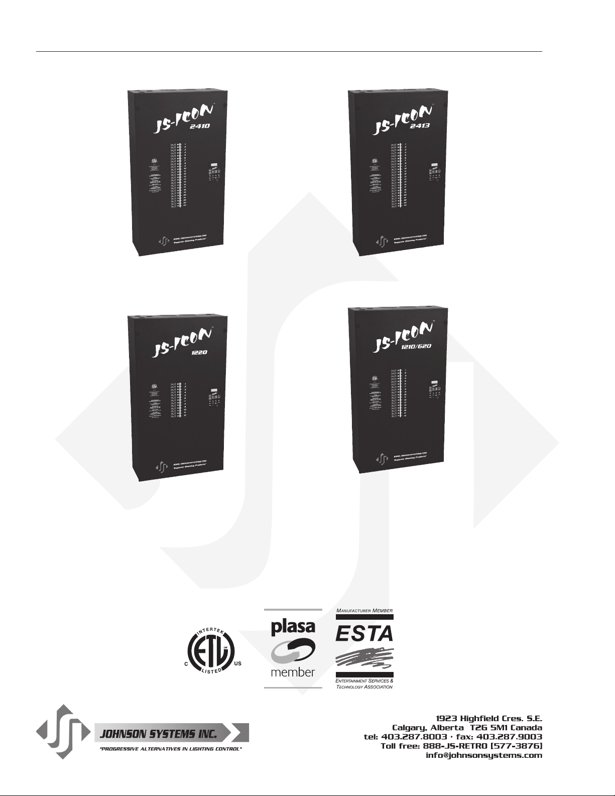
JSI-ICON™ Series Dimmer/Relay Racks
JS-ICON™ 2410
24 x 10 Amp (1200 Watt) dimmers
JS-ICON™ 1220
12 x 20 Amp (2400 Watt) dimmers
JS-ICON™ 2413
24 x 13 Amp (1560 Watt) dimmers
JS-ICON™ 1210/620
12 x 10 Amp (1200 Watt)
+ 6 x 20 Amp (2400 Watt) dimmers
User Manual
JS-ICON™ Series Dimmers
Rev. 3
www.johnsonsystems.com
 Loading...