

Page 1
User Manual
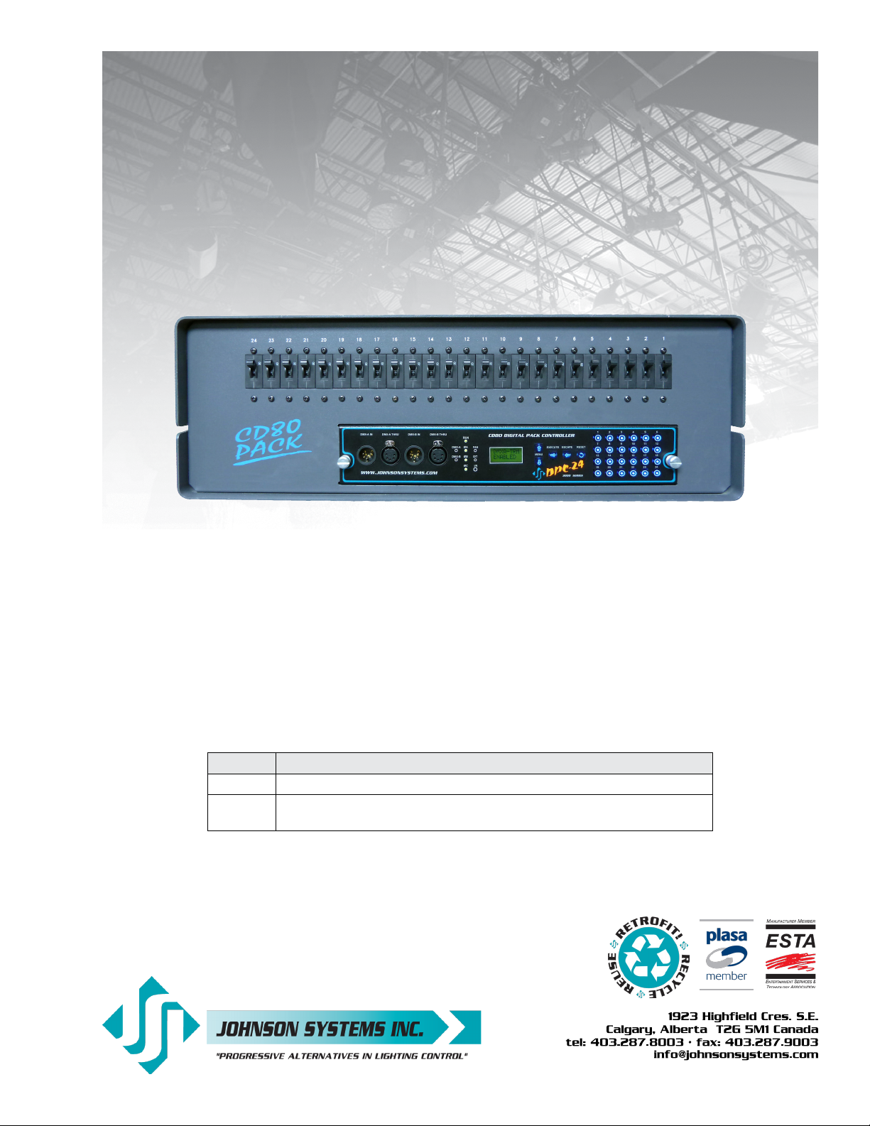
DPC-12 & DPC-24
3000 Series Digital Pack Controller
Control Retrofit for CD80 Portable Dimmer Packs
Model Description
DPC-12 CD80 12 x 2.4kW, 6 x 6kW and 6 x 12kW Portable Dimmer Packs.
DPC-24 CD80 24 x 1.2 kW and 24 x 2.4kW Portable Dimmer Packs
CD80 48 x 2.4kW Compact Rolling Racks (requires 2 per rack).
JOHNSON SYSTEMS INC.
www.johnsonsystems.com
Page 2
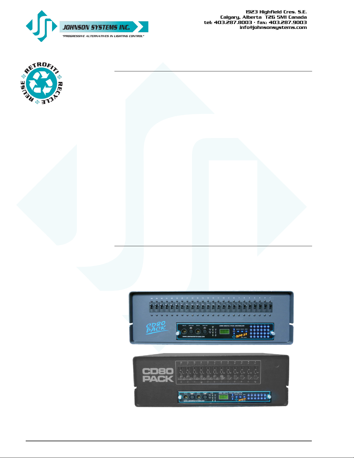
Table of Contents
Warranty ..........................................................................................................2
Introduction ......................................................................................................3
Packaging & Contents .....................................................................................3
Installation .......................................................................................................3
DPC-24/12 Circuit Board .................................................................................5
DPC-12 and DPC-24 Control Module Face Panels.........................................6
Dual DMX Input and Thru Connectors ............................................................7
User Interface ..................................................................................................7
LCD Display.....................................................................................................8
Programming Switches....................................................................................8
12 or 24 Local Buttons/Switches .....................................................................8
System Status - LED Indicators.......................................................................9
System Status - LCD Display ..........................................................................9
Quick Programming Reference to System Conguration Menu Items .......... 11
Detailed Programming of System Conguration Menu Items........................12
Troubleshooting Reference ...........................................................................23
Important Hard-key Information .....................................................................23
Warranty
DPC-12 and DPC-24 retrot control modules comes with a standard one (1)
year limited warranty against defects in parts and workmanship.
Extended warranties of up to ten (10) years are available at the time of
purchase. For details visit www.johnsonsystems.com/warranties.htm
2
www.johnsonsystems.com
Page 3
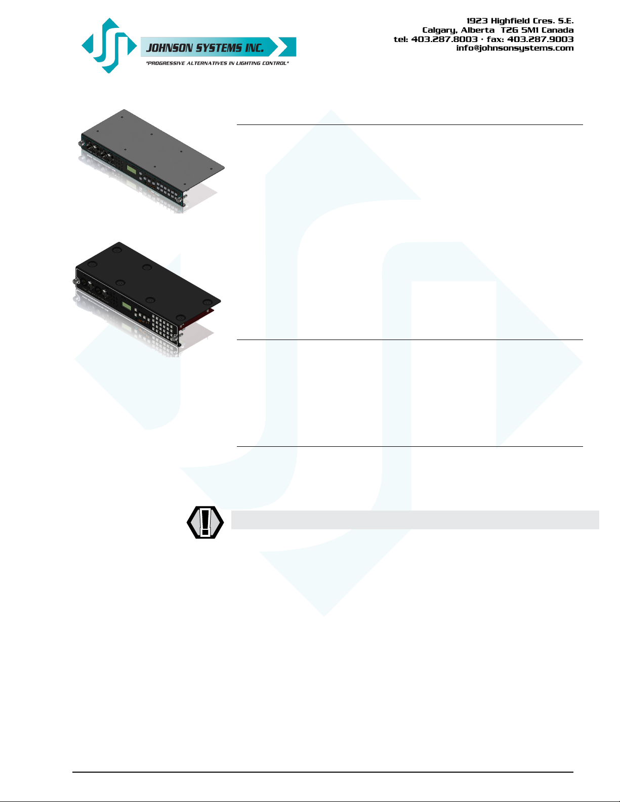
DPC-12
Introduction
Digital Pack Controllers (DPC’s) are a next generation retrot electronics
package designed specically for upgrading Strand CD80 12 channel and 24
channel portable dimmer packs, as well as 48 channel compact rolling racks.
This direct plug-in replacement control module supersedes all previous
generations of OEM and aftermarket controllers in both reliability and
features.
“Basic Mode”, on power up, was designed specically at the request of
major U.S. studios and rental houses. Advanced features for the more
selective user allow customization of over 30 additional features. Advanced
next generation “3000 Series” hardware and software designs reduce
stand-by power consumption to less than 1 Watt. Exclusive “lamp warming”
techniques extends lamp life considerably.
DPC-24
Packaging & Contents
DPC-12 and DPC-24 retrot control modules are shipped in a custom
designed box and packaging for protection of the unit. It is recommended to
keep the box and packaging stored in a safe place. In the unlikely event that
the system needs to be returned to the JSI Factory, the packaging will help
prevent shipping damage and maintain warranty.
Installation
DPC-12 and DPC-24 retrot control modules are a “plug-and-play”
replacement for the OEM (Original Equipment Manufacturer) CD80 dimmer
pack control module.
• Disconnect (turn off) the power supply to the CD80 dimmer pack.
WARNING! Verify all power is disconnected (turned off) before proceeding.
Removal of the old CD80 pack control module
• Loosen the two (2) thumbscrews located on each end of the control
module.
• Carefully pull straight out on the thumbscrews to remove the control
module.
• Determine if the DMX input is connected internally, on a terminal block
mounted inside the CD80 dimmer pack. If it is, determine which rear
connector the DMX comes in though.
Installation of the new DPC-12 or DPC-24 retrofit control
module
• Remove your new DPC-12 or DPC-24 retrot control module from the
box.
www.johnsonsystems.com 3
Page 4
(EDGE3) (EDGE2)
CD80 DIGITAL PACK CONTROLLER
REV.1 1132
SERIAL NUMBER
3000 SERIES
DPC-24/12
FAN FUSE
REPLACE WITH
2A 250V
FAST-ACTING
GMA TYPE
FUSE ONLY!
CAUTION: AC LINE VOLTAGE!
MOVE JUMPERS (x3)
TO LEFT-HAND SIDE POSITION
TO ENABLE INTERNAL DMX-B INPUT
EDGE2, 16-Pin
Edge Connector
PIN FUNCTION
13 DMX-B Input Data+
15 DMX-B Input Data-
16 DMX-B Input Shield / Common
EDGE3, 20-Pin
Edge Connector
PIN FUNCTION
1 DMX-B Input Shield / Common
2 DMX-B Input Data+
4 DMX-B Input Data-
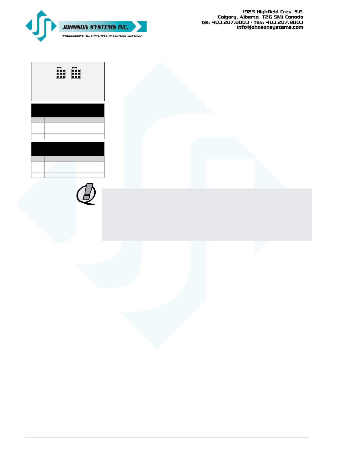
• If the DMX input is connected internally, on a terminal block mounted
inside the CD80 dimmer pack, jumpers will need to be moved on the
DPC-24/12 circuit board to enable the DMX-B input. To enable the internal
DMX through the EDGE2 connector on the DPC-24/12 circuit board, move
the three (3) jumpers on JP2 to the left-hand side position. To enable the
internal DMX through the EDGE3 connector on the DPC-24/12 circuit
board, move the three (3) jumpers on JP3 to the left-hand side position.
• Line up the DPC-12 or DPC-24 control module with the guide rails on each
end of the control module slot.
• Carefully slide the DPC-12 or DPC-24 control module in until the
connectors on the DPC-24/12 circuit board touch the rear connectors
inside the CD80 dimmer pack.
• Line up the two (2) thumbscrews on the DPC-12 or DPC-24 with the
mounting holes on the CD80 dimmer pack.
• Firmly push the DPC-12 or DPC-24 in on both ends until the control
module is fully seated.
NOTE: If it feels like the control module isn’t fully seated or doesn’t slide in
easily, it may be necessary to re-align the rear connectors inside
the CD80 dimmer pack to their upper most position, due to the
inconsistencies in the assembly of the CD80 dimmer pack. This can
be accomplished by loosening the two (2) mounting screws on each
end of the rear connectors by half a turn, sliding the connectors up as
much as possible and then re-tightening the mounting screws.
4
• Tighten the two (2) thumbscrews to secure the DPC-12 or DPC-24 in the
CD80 dimmer pack.
Turn on and test the new DPC-12 or DPC-24 retrofit control
module
• Connect (turn on) the power supply to the to the CD80 dimmer pack.
• Verify the operation of the system status LED indicators, LCD display and
programming switches.
• Refer to the programming section of this manual for system conguration.
• Test the system thoroughly to ensure everything is functioning properly.
• Verify all of the dimmer control outputs have the correct phase referencing.
If a dimmer control output is patched to the incorrect phase reference, the
dimmer will not dim correctly and will go to full output at around 1% DMX
input. The factory conguration for DPC-12 and DPC-24 control modules
is for standard three-phase applications, with the dimmer phase reference
patch set at AAAABBBBCCCC… For standard single-phase applications,
set the default (DEFAULT) menu for single-phase (1ØPATCH) operation,
with the dimmer phase reference patch set at AAAAAAAACCCCCCCC…
The phase patch (Ø-PATCH) menu must be used to congure non-
standard applications.
• Verify the fan inside the CD80 dimmer pack is operating properly. The fan
should turn on with between 6-7% DMX (or other) control – when DMX (or
other) control drops below 6-7%, there is a 5 minute timeout on the fan to
ensure the dimmers have been cooled sufciently. If required, replacement
fans are available (Johnson System Inc., Part Number: CF-CD80P).
www.johnsonsystems.com
Page 5
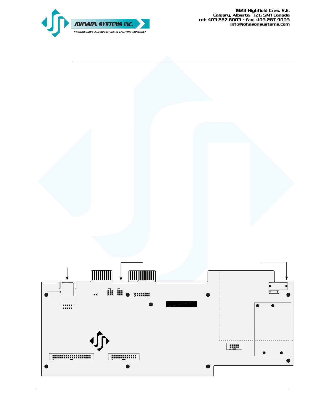
DPC-24/12 Circuit Board
The DPC-24/12 circuit board is the central electronic control system (a.k.a. brain) for DPC-12 and
DPC-24 retrot control modules. The edge connectors (EDGE1, EDGE2, EDGE3 and EDGE5 (for
DPC-24 only)) located on the upper edge of the DPC-24/12 circuit board connects with the OEM
connectors inside the CD80 dimmer pack.
There are three (3) items of interest located on the DPC-24/12 circuit board:
• Located on the upper left-hand side of the board, there is a removable EEPROM memory
module. The EEPROM memory module slides into the PORT1 connector located on
the upper left-hand side of the board. The EEPROM memory module is used to backup
important conguration settings and may be removed for safe storage. The EEPROM
memory module can also be used for rmware updates. Refer to menu items “EEPROM”,
“FW-LOAD”, “RESTORE” and “BACKUP” on page 19, 20 and 21 for further details.
• Located on the upper-central left-hand side of the board, there are two sets of jumpers. If
the DMX input is connected internally, on a terminal block mounted inside the CD80 dimmer
pack, the jumpers will need to be moved on the DPC-24/12 circuit board to enable the
DMX-B input. To enable the internal DMX through the EDGE2 connector on the DPC-24/12
circuit board, move the three (3) jumpers on JP2 to the left-hand side position. To enable the
internal DMX through the EDGE3 connector on the DPC-24/12 circuit board, move the three
(3) jumpers on JP3 to the left-hand side position.
• Located on the upper right-hand side of the board, there is a fan fuse. The fuse is required
for safety and protects the fan control circuitry on the DPC-24/12 circuit board. If the fuse
is blown (open), the “FAN” LED illuminates. A blown (open) fuse suggests the fan may
be defective and needs to be replaced (Johnson System Inc., Part Number: CF-CD80P).
Replace the fuse with a 2A, 250V, fast-acting, GMA type fuse only!
EEPROM Memory Module Enable Internal DMX-B Input Jumpers Fan Fuse
EEPROM
MEMORY
MODULE
MADE IN CANADA
EEPROM
BACKUP &
FIRMWARE
UPDATE
(EDGE3) (EDGE2)
MOVE JUMPERS (x3)
TO LEFT-HAND SIDE POSITION
TO ENABLE INTERNAL DMX-B INPUT
WWW.JOHNSONSYSTEMS.COM
DPC-24/12
CD80 DIGITAL PACK CONTROLLER
SERIAL NUMBER
3000 SERIES
REV.1 1132
FAN FUSE
REPLACE WITH
2A 250V
FAST-ACTING
GMA TYPE
FUSE ONLY!
CAUTION: AC LINE VOLTAGE!
www.johnsonsystems.com 5
Page 6
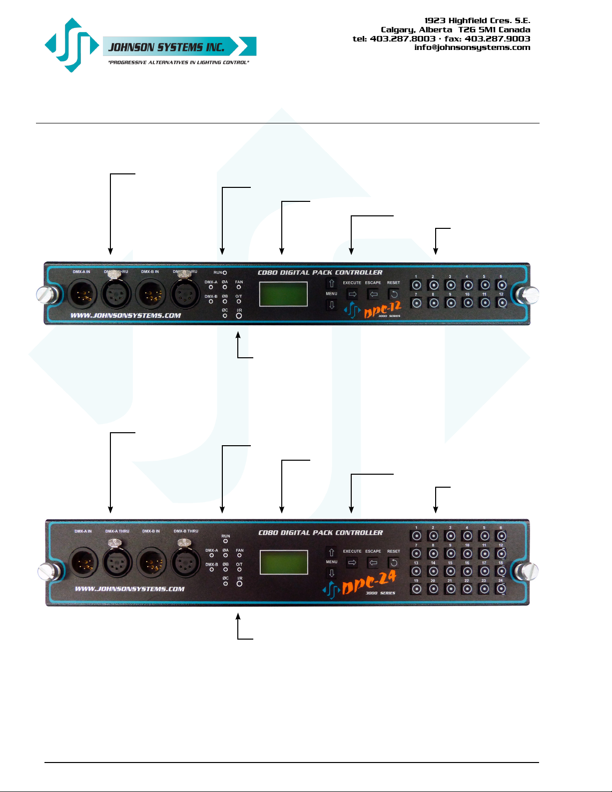
DPC-12 and DPC-24 Control Module Face Panels
Dual DMX Input and Thru Connectors (5-Pin XLR)
System Status - LED Indicators
LCD Display
Programming Switches
Infrared (I/R) LED for Printer
Local Button/Switches
(a.k.a. Bump Buttons)
Dual DMX Input and Thru Connectors (5-Pin XLR)
System Status - LED Indicators
Infrared (I/R) LED for Printer
LCD Display
Programming Switches
Local Button/Switches
(a.k.a. Bump Buttons)
6
www.johnsonsystems.com
Page 7
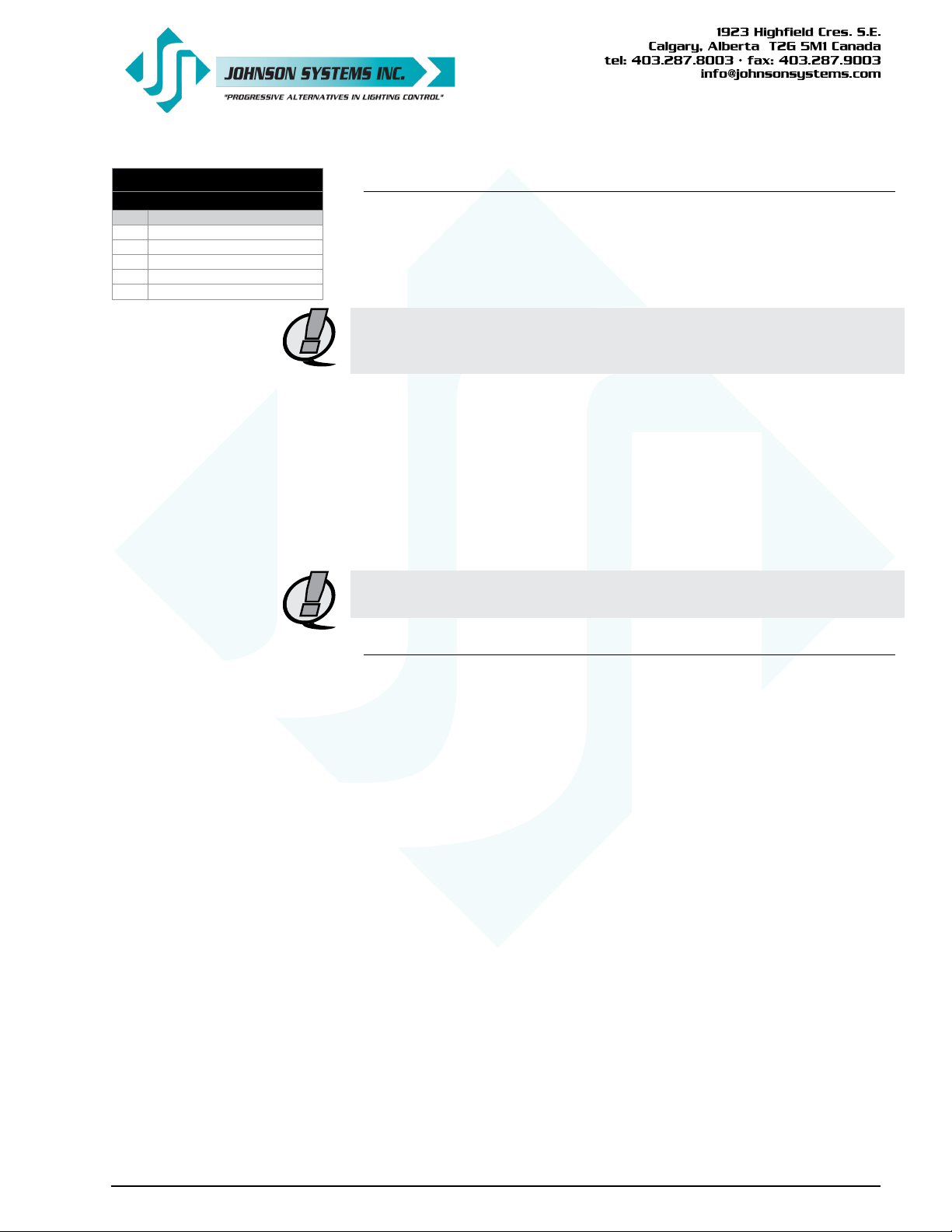
DMX Input and Thru
5-Pin XLR Connectors
PIN FUNCTION
1 DMX Shield / Common
2 DMX Data3 DMX Data+
4 Pass Thru Connection
5 Pass Thru Connection
Dual DMX Input and Thru Connectors
DPC-12 and DPC-24 control modules are equipped with dual (2) optoisolated DMX inputs. The DMX-A and DMX-B input and thru connectors (5pin XLR) are located on the front panel of the control module. A built-in DMX
protocol manager can be congured for various applications. Refer to menu
item “DMX MODE” on page 14 for further details.
NOTE: If DMX is connected internally, on a terminal block mounted inside
the CD80 dimmer pack, the DMX-B input is utilized, and the front
panel DMX-B input should not be used or data collision will occur.
• Complies with USITT DMX512-A (ANSI E1.11 - 2008), standard protocol
for digital data control.
• Recommended cable is Beldon 9829, 9842, Cat 5 or equivalent (lowcapacitance, twisted pair).
• Wiring must follow a daisy-chain topology.
• Maximum of 32 receiving devices on a single DMX line.
• Maximum cable length is 1,500 feet (455 meters).
• For more information, Google DMX, or visit:
http://www.usitt.org/DMX512FAQ.aspx
NOTE: Ensure only the last (end-of-line) DMX receiving device is
terminated!
User Interface
DPC-12 and DPC-24 retrot control modules are equipped with a user
interface. The user interface provides access to all programming and
conguration settings. System status is easily visible on the LCD display
and LED indicators. An infrared (I/R) LED allows for printout of all system
conguration settings when used with a hand held infrared printer (Johnson
System Inc., Part Number: JS-IP).
All of the programming is accomplished using four (4) switches. Within a few
minutes most users will nd the menu structure very intuitive and easy to
navigate. All conguration settings are automatically stored in the on-board
EEPROM.
www.johnsonsystems.com 7
Page 8
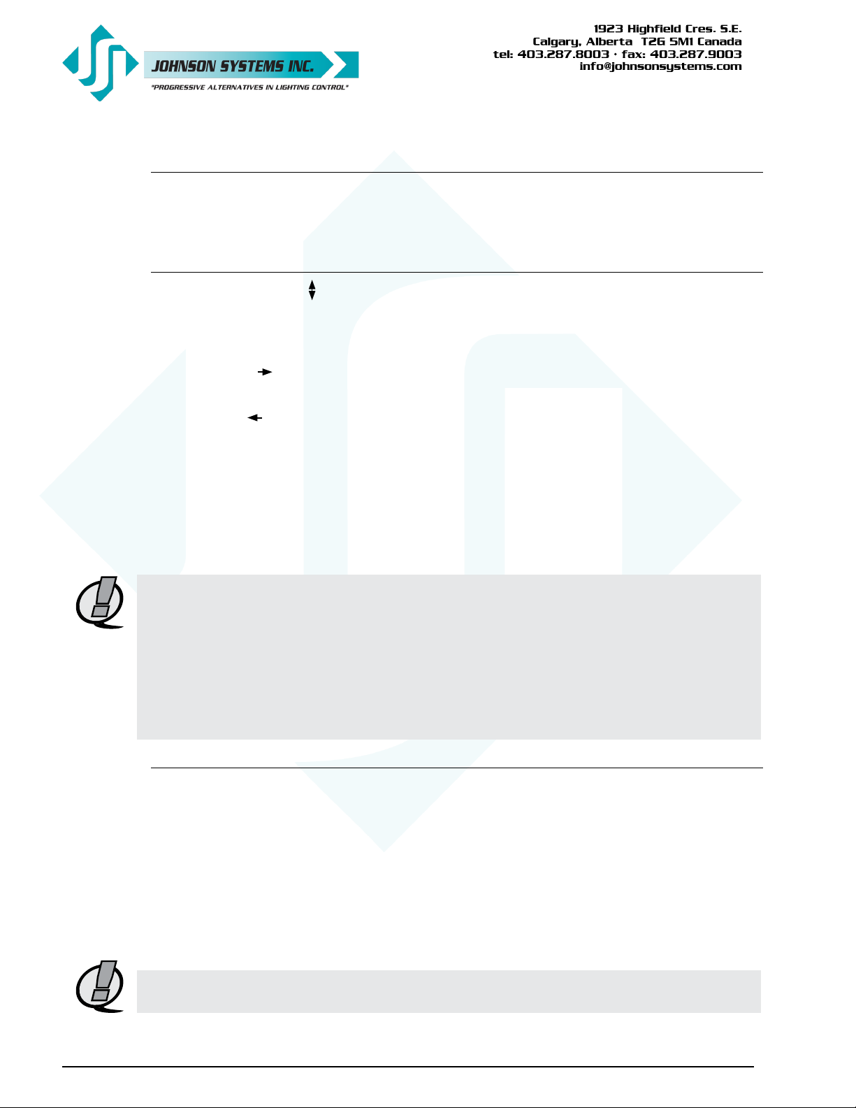
LCD Display
The LCD display is capable of displaying 2 lines of 8 characters. A backlight automatically comes
on when activity is sensed. The LCD contrast can be easily adjusted for optimum viewing.
Refer to menu item “LCD VIEW” on page 22 for further details.
Programming Switches
The MENU UP/DOWN ( ) switches are used for navigating through the various system
conguration menu items. They also allow for programming of other specic parameters within
a selected menu. Pressing and holding either switch will speed up the scroll rate, which can be
helpful to speed up the conguration time.
The EXECUTE ( ) switch is normally used to select/enter a menu item, advance forward within
a selected menu item, or toggle between parameters within a selected menu item.
The ESCAPE ( ) switch is normally used to back up within a selected menu item one step at a
time or exit the menu completely.
The RESET switch has two purposes. First, it allows for quick exit from a menu item after a
programming change and automatically puts the system into normal run mode. Second, it provides
a soft reboot for the systems microcontroller.
The programming switches are backlit with blue LED’s. The LED’s automatically turn on when
activity is sensed. The LED intensity can be adjusted in the “LED INT” menu. Refer to page 24 for
further details.
NOTE: When the DPC-12 or DPC-24 is powered up, the menus are “LOCKED!!” with access
only to the basic system conguration menus, which includes setting the DMX start
address as well as enabling or disabling the end-of-line DMX termination. The menus
need to be “UNLOCKED” to access the advanced system conguration menus. To
toggle between “LOCKED!!” and “UNLOCKED” press and hold down the EXECUTE and
then ESCAPE switches at the same time for 4-5 seconds.
NOTE: A detailed procedure for programming all system conguration menu items can be found
on page 11 to 22.
12 or 24 Local Buttons/Switches
The 12 or 24 local buttons/switches (a.k.a. bump buttons) can be congured for two different
modes. They can either be congured as bump buttons or to activate scenes. Refer to menu item
“L-BUTTON” on page 17 for conguration details.
The local buttons are backlit with blue LED’s. The LED’s indicate the approximate control level for
each of the 12 or 24 dimmers. As the control level for a dimmer is increased, the intensity of the
LED increases.
For a 6 dimmer circuit CD80 pack, button 1 controls and indicates dimmer 1, button 3 controls
and indicates dimmer 2, button 5 controls and indicates dimmer 3, button 7 controls and indicates
dimmer 4, button 9 controls and indicates dimmer 5 and button 11 controls and indicates dimmer 6.
NOTE: To congure a DPC-12 for 6 PACK (6 dimmer circuit CD80 pack) operation,
select 6 PACK in the DEFAULTS menu..
8
www.johnsonsystems.com
Page 9
System Status - LED Indicators
RUN (Green)
Illuminates when the power is on and the microcontroller status is in normal run mode. The LED
ashes once every 2 seconds when the system is in STANDBY mode.
ØA, ØB and ØC (Green)
Illuminates when the line voltage for each phase is within the acceptable range of 100VAC to
130VAC for 120VAC operation and 200VAC to 260VAC for 240VAC operation, and the zero-cross
reference circuitry is functioning properly. The LED will ash slowly (once per second) when an
under-voltage is sensed - less than 100VAC for 120VAC operation, and less than 200VAC for
240VAC operation. The LED will ash quickly (twice per second) when an over-voltage is sensed
- greater than 130VAC for 120VAC operation, and greater than 260VAC for 240VAC operation.
DMX-A (Yellow)
Illuminates when valid DMX is received on the DMX-A input. Flashes when invalid DMX is
received.
DMX-B (Yellow)
Illuminates when valid DMX is received on the DMX-B input. Flashes when invalid DMX is
received.
FAN
Illuminates when a blown (open) fan fuse is sensed. A blown (open) fuse suggests the fan may
be defective and needs to be replaced (Johnson System Inc., Part Number: CF-CD80P). Replace
the fuse with a 2A, 250V, fast-acting, GMA type fuse only!
O/T
Illuminates and ashes twice per second when an over-temperature is sensed via the OEM
thermostat, mounted on the heat-sink inside the CD80 dimmer pack. The thermostat closes
when an over-temperature condition of 180°F ±7°F (82°C ±4°C) is reached. All dimmer outputs
are disabled and the fan is turned on to full until the thermostat temperature drops to within
specication.
System Status - LCD Display
When DMX is being received, the top line of the LCD display shows the DMX-A start address
(“DMXA:001” to “DMXA:512”). When DMX is not being received, the top line of the LCD display
shows “DPC-12” or “DPC-24”, unless the system is in standby mode, then “STANDBY!” is
displayed.
The bottom line of the LCD display shows the current status of the system unless the system
conguration menu items are being accessed. Below are descriptions for each status indication.
NO RX!
Displayed when DMX is not being received on either input and the system is not in scene mode.
AXXXBXXX
Displayed when valid DMX is being received on one or both inputs and both inputs are not
terminated. “A” and “B” represent the DMX-A and DMX-B inputs while “XXX” represents the
number of channels being received in each packet of data. For example, if the system is receiving
512 channels on DMX-B and DMX-A is disconnected, the display will show “A000B512”.
www.johnsonsystems.com 9
Page 10

XXX XXX
Same as above except the “A” and “B” is replaced with “ ” to indicate if one or both of the DMX
inputs are terminated. For example, if the system is receiving 48 channels on DMX-A and 512
channels on DMX-B, with only DMX-A terminated, the display will show “ 048B512”. Refer to
menu items “DMXA-TRM” and “DMXB-TERM” on page 12 for further details.
SH XX:YY
Displayed when DMX is disconnected and the systems predetermined DMX status hold (SH) time
is counting down. “XX” represents minutes while “YY” represents seconds. Refer to menu item
“SH TIME” on page 15 for further details.
INF HOLD
Displayed when DMX is disconnected and the systems predetermined DMX status hold (SH) time
is set for innite (INF) hold. Refer to menu item “SH TIME” on page 15 for further details.
SCENE:XX
Displays the scene (1 to 12 or 24) that is currently activated. Refer to menu item “L-BUTTON”
on page 17 for further details.
REM-TEMP
Displayed when the remote over-temp sensor is triggered via the OEM thermostat, mounted on
the heat-sink inside the CD80 dimmer pack. The thermostat closes when an over-temperature
condition of 180°F ±7°F (82°C ±4°C) is reached. All dimmer outputs are disabled and the fan is
turned on to full until the thermostat temperature drops to within specication.
CTL-TEMP
Displayed when the microcontroller senses an internal over-temperature condition of 185°F (85°C)
or more. All dimmer outputs are disabled and the fans are turned on to full until the temperature
cools down to 178°F (81°C) or less. Refer to menu item “CTL TEMP” on page 18 to view the
current microcontroller temperature.
Ø ERROR!
Displayed when an error is sensed on any of the input power phases. A phase error can be caused
from an under-voltage of less than 100VAC for 120VAC operation and 200VAC for 240VAC
operation, an over-voltage of greater than 130VAC for 120VAC operation and 260VAC for 240VAC
operation, or if a zero-cross phase reference is not detected.
FAN ERR!
Displayed when a blown (open) fan fuse is sensed. A blown (open) fuse suggests the fan may be
defective and needs to be replaced (Johnson System Inc., Part Number: CF-CD80P). Replace the
fuse (located on the DPC-24/12 circuit board) with a 2A, 250V, fast-acting, GMA type fuse only!
RTC ERR!
Displayed when the system detects a runtime counter (RTC) error. This occurs when there
is an invalid hard-key code and the runtime counter is greater than 2160 hours (90 days).
Refer to menu item “HARD-KEY” on page 18 for further details.
LOCKED!!
When the DPC-12 or DPC-24 is powered up, the menus are “LOCKED!!” with access only to
the basic system conguration menus, which includes setting the DMX start address as well as
enabling or disabling the end-of-line DMX termination. The menus need to be “UNLOCKED”
to access the advanced system conguration menus. To toggle between “LOCKED!!” and
“UNLOCKED” press and hold down the EXECUTE and then ESCAPE switches at the same time
for 4-5 seconds.
10
www.johnsonsystems.com
Page 11

Quick Programming Reference to System Configuration Menu Items
Basic Menus
1. ADDRESS Set the DMX start address.
2. DMXA-TRM Enable or disable termination on the DMX-A input.
3. DMXB-TRM Enable or disable termination on the DMX-B input.
Advanced Menus
4. SCENESET Enable and setup 12 or 24 different backup scenes.
5. FADETIME Set the fade time for each of the 12 or 24 scenes from 0 to 99 seconds.
6. SNAPSHOT Record DMX levels into the backup scenes.
7. DIM TEST Test the dimmer outputs one at a time, or all at once.
8. MONITOR View the control level to each dimmer output.
9. DMX MODE Congure the mode of the on-board DMX protocol manager.
10. 2 RM SET Set the two room assignment for each of the dimmer outputs.
11. SH TIME Set the DMX status hold time from 0 to 99 minutes or innite.
12. DC PATCH Congure the dimmer to channel patch for the dimmer pack.
13. DIM CURV Congure the dimmer curve for each output.
14. VOUT LIM Set the maximum RMS output voltage for each dimmer.
15. REGULATE Enable or disable the dimmer output voltage regulation.
16. STANDBY Enable or disable the power savings standby mode.
17. TEST INC Set the test increment units to percent or hexadecimal.
18. L-BUTTON Set the mode of the 12 or 24 local buttons to scene, bump or disabled.
19. Ø-PATCH Set the zero-cross phase reference for each dimmer control output circuit.
20. V-RANGE Set the supply voltage range for 120 Volts or 240 Volts operation.
21. LINE V View the RMS line voltage for each power phase.
22. LINE F View the line frequency of phase A.
23. CTL TEMP View the temperature of the microcontroller.
24. RTIME View the total run time of the microcontroller.
25. HARD-KEY View the microcontroller’s unique six-character hard-key code.
26. SERIAL# View the microcontroller’s unique six-character silicone serial number.
27. VERSION View the microcontroller’s rmware version.
28. EEPROM View the type of EEPROM memory module plugged in.
29. FW-LOAD Load new rmware into the microcontroller via the EEPROM memory module.
30. RESTORE Restore parameters saved in the EEPROM memory module.
31. BACKUP Backup parameters and save them in the EEPROM memory module.
32. PRINTOUT Print various system conguration settings using a hand held infrared printer.
33. DEFAULTS Set various system conguration settings to the factory default.
34. LED INT Set the LED intensity for the programming switches.
35. LCD VIEW Adjust the contrast of the LCD Display for optimum viewing.
www.johnsonsystems.com 11
Page 12
Detailed Programming of System Configuration Menu Items
NOTE: When the DPC-12 or DPC-24 is powered up, the menus are “LOCKED!!” with access
only to the basic system conguration menus, which includes setting the DMX start
address as well as enabling or disabling the end-of-line DMX termination. The menus
need to be “UNLOCKED” to access the advanced system conguration menus. To
toggle between “LOCKED!!” and “UNLOCKED” press and hold down the EXECUTE
and then ESCAPE switches at the same time for 4-5 seconds.
The sequence of the following system conguration menu items appear as the MENU DOWN ( )
switch is pressed. Pressing the MENU UP ( ) switch will sequence the system conguration
menu items in the opposite order. Pressing and holding either of the MENU UP/DOWN ( )
switches will speed up the scroll rate, which can be helpful to speed up the conguration time.
Basic Menus
1. ADDRESS Set the DMX start address.
The DMX start address can be assigned from 001 to 512, and is common to both
DMX inputs. When DMX MODE is set for DMX A+B operation, each of the DMX
inputs can be assigned to a separate DMX start address. The DMX inputs are merged
and DMX-B is offset by the number of DMX-A channels.
Press EXECUTE to enter the menu.
DMXA>001 Displays the current DMX start address for both DMX inputs.
DMXA>512 Press MENU ( ) to modify and select the desired DMX start address.
DMXA>001 Press both MENU ( ) simultaneously to toggle to DMX start address 001.
DMXA>025 Press EXECUTE to save the selected DMX start address.
DMXB>001 *Press EXECUTE to advance to select the DMX-B start address.
DMXB>512 *Press MENU ( ) to modify and select the desired DMX start address.
#CHA=>01 *Press EXECUTE to advance to select the number of DMX-A channels.
#CHA=>24 *Press MENU ( ) to modify the number of DMX-A channels from 01 to 24.
Press ESCAPE to exit the menu and save the selected DMX start address.
Press RESET to exit the menu without saving.
The menu will automatically timeout after 2 minutes of inactivity and save.
NOTE: * DMX MODE must be set for DMX A+B operation to access this feature.
12
2. DMXA-TRM Enable or disable termination on the DMX-A input.
Activates and deactivates a 120Ω termination resistor. DMX termination is indicated
on the LCD display when DMX is being received. When the DMX-A input is not
terminated (DISABLED) the LCD display will read AXXXBXXX. When the DMX-A
input is terminated (ENABLED) the LCD display will read TMXXXBXXX.
ENABLED Press EXECUTE to toggle termination from ENABLED to DISABLED.
DISABLED Press EXECUTE to toggle termination from DISABLED to ENABLED.
Any change in the conguration is automatically saved.
NOTE: Ensure only the last (end-of-line) DMX receiving device is terminated!
3. DMXB-TRM Enable or disable termination on the DMX-B input.
Activates and deactivates a 120Ω termination resistor. DMX termination is indicated
on the LCD display when DMX is being received. When the DMX-B input is not
terminated (DISABLED) the LCD display will read AXXXBXXX. When the DMX-B
input is terminated (ENABLED) the LCD display will read AXXXTMXXX.
ENABLED Press EXECUTE to toggle termination from ENABLED to DISABLED.
DISABLED Press EXECUTE to toggle termination from DISABLED to ENABLED.
Any change in the conguration is automatically saved.
NOTE: Ensure only the last (end-of-line) DMX receiving device is terminated!
www.johnsonsystems.com
Page 13
Advanced Menus
4. SCENESET Enable and setup 12 or 24 different backup scenes.
When scene mode (SCENESET) is activated the selected scene will be held with
no timeout until the menu is exited. The 12 or 24 local buttons (L-BUTTON) are
automatically set for SCENE mode and can be used to activate scenes. The 12 or 24
control channel levels are congured within the menu and can be modied on the y.
Scene mode is useful when an external controller is not available and independent
internal control is required.
Press EXECUTE to enter the menu and activate scene mode.
SCENE>01 Displays the scene (01) to be activated.
SCENE>24 Press MENU ( ) to select a different scene from 01 to 12 or 24.
CTRL: ON Control (CTRL) is ON via the selected scene.
CTRL:DMX Control (CTRL) is via DMX and takes priority over scene mode.
CTRL:HLD Control (CTRL) is via DMX status hold (HLD) and takes priority over scene mode.
CTRL:INF Control (CTRL) is via DMX status hold (INF) and takes priority over scene mode.
SCENE>24 Press EXECUTE to activate the selected scene.
SCENE:24 The colon (:) ashes twice per second while fading to the selected scene.
SCENE:24 The colon (:) stops ashing when fade is complete and the selected scene is active.
SCENE>24 Press MENU ( ) to select a different scene from 01 to 12 or 24.
SCENE 24 Press EXECUTE to modify the selected scene.
C>01L 00 The second line on the LCD indicates the control channel (C) and level (L).
C>24L 00 Press MENU ( ) to select the control channel (C) to modify from 01 to 12 or 24.
C 24L>00 Press EXECUTE to toggle from channel (C>) to level (L>) selection.
C>24L 00 Press ESCAPE to toggle from level (L>) to channel (C>) selection.
C 24L>FL Press MENU ( ) to select the output level (L) for the selected channel from 00 to FL.
CLEAR??? Press EXECUTE to clear the selected preset, and set all channels to 00 level.
SURE ??? Press EXECUTE if you are sure to clear the selected preset.
DONE !!! Indicates the selected preset has been cleared.
WAIT... Press ESCAPE to exit and the menu and save programmed scene levels.
Press ESCAPE to back-up within the menu, or exit/deactivate scene mode.
Press RESET to exit scene mode without saving programmed scene levels.
NOTE: When scene mode is activated, DMX and DMX status hold (SH-TIME)
automatically takes precedence over scene mode. Scene mode will only
activate dimmers assigned to room “A”.
5. FADETIME Set the fade time for each of the 12 or 24 scenes from 0 to 99 seconds.
The factory default is 5 seconds for all 12 or 24 scenes.
Press EXECUTE to enter the menu.
S>01T 05 Displays the scene (S>01) and assigned fade time (T 05).
S>24T 05 Press MENU ( ) to select a different scene from 01 to 12 or 24.
S 24T>05 Press EXECUTE to toggle between scene (S>) and fade time (T>) selection.
S 24T>99 Press MENU ( ) to select a different fade time from 00 to 99 seconds.
Press ESCAPE to exit the menu and save the selected fade time.
Press RESET to exit the menu without saving.
The menu will automatically timeout after 2 minutes of inactivity and save.
www.johnsonsystems.com 13
Page 14
6. SNAPSHOT Record DMX levels into the backup scenes.
Provides a quick and easy way to save control channel levels into each of the 01 to 12
or 24 backup scenes using a DMX source.
Press EXECUTE to enter the menu and activate snapshot mode.
SAVE >01 Press MENU ( ) to select a different scene from 01 to 12 or 24.
SCENE>24 Press EXECUTE to store DMX levels in the selected scene.
SURE ??? Press EXECUTE if you are sure the DMX levels are set as intended.
DONE !!! DMX levels have now been saved in the selected scene.
NO RX! DMX is not being received on either input, so a snapshot is not possible.
Press ESCAPE to back-up within the menu, or exit/deactivate snapshot mode.
Press RESET to exit/deactivate snapshot mode.
7. DIM TEST Test the dimmer outputs one at a time, or all at once.
A technician’s best friend! Used for troubleshooting the dimmer outputs and eld wiring
to the load.
Press EXECUTE to enter the menu and activate dimmer test mode.
D 01L>00 Displays the active dimmer (D) and the test level (L).
D 01L>50 Press MENU ( ) to select the desired test level.
D 01L>FF Press ESCAPE to toggle the test level from full-on (FF) and off (00).
D>01L FF Press EXECUTE to toggle between the dimmer (D>) and the test level (L>).
D>ALL FF Press MENU ( ) to select the active dimmer from 01 to 12 or 24 or ALL.
Press ESCAPE or RESET to exit the menu.
The menu will automatically timeout after 2 minutes of inactivity.
8. MONITOR View the control level to each dimmer output.
The dimmer control level is displayed as a 9-bit value from 000 to 512. This menu does
not timeout automatically and will continue to monitor indenitely.
Press EXECUTE to enter the menu and activate monitor mode.
D>01L000 Press MENU ( ) to select the dimmer (D) output to monitor from 01 to 12 or 24.
D>24L512 Display shows dimmer 24 has full-on control.
Press ESCAPE or RESET to exit the menu.
14
NOTE: The control level value will not reach 512 when voltage output limiting is
activated, or when regulation is enabled and the line voltage is greater than
118VAC for 120VAC operation or 236VAC for 240VAC operation.
9. DMX MODE Congure the mode of the on-board DMX protocol manager.
There are ve different mode settings for the DMX protocol manager.
Priority A (PTY A) and Priority B (PTY B) modes are intended for the implementation of a
backup DMX source. Priority A (PTY A) sets the DMX-A input as the priority, and ignores
the DMX-B input when the DMX-A input is active. Priority B (PTY B) sets the DMX-B
input as the priority, and ignores the DMX-A input when the DMX-B input is active.
Merge (MERGE) mode combines both DMX inputs with highest-takes-precedence (HTP)
operation. Merge mode allows for simultaneous DMX control of the dimmers from both
inputs, and is the default for the system.
Dual Universe DMX (DMX A+B) mode provides a method to combine two universes
of DMX within one system. It permits two independent DMX sources to be active on
the DMX inputs, with each having a separate DMX start address. The DMX inputs are
merged and DMX-B is offset by the number of DMX-A channels programmed via the
ADDRESS menu (see page XX for further details). This feature is typically used when
a system is at the end of one DMX universe (DMX-A) and the beginning of another
(DMX-B).
Two Room (2 ROOM) mode enables the room (A or B) assignment for each of the
dimmer outputs via the 2 RM SET menu.
www.johnsonsystems.com
Page 15
PTY A Press EXECUTE to toggle into Priority A (PTY A) mode.
PTY B Press EXECUTE to toggle into Priority B (PTY B) mode.
MERGE Press EXECUTE to toggle into Merge (MERGE) mode.
DMX A+B Press EXECUTE to toggle into Dual Universe DMX (DMX A+B) mode.
2 ROOM Press EXECUTE to toggle into Two Room (2 ROOM) mode.
Press ESCAPE or RESET to exit the menu.
Any change in the conguration is automatically saved.
10. 2 RM SET Set the two room assignment for each of the dimmer outputs.
This menu is used to assign each of the 12 or 24 dimmer outputs to room “A” or
room “B”. Dimmer outputs assigned to room “A” are controlled via the DMX-A input.
Dimmer outputs assigned to room “B” are controlled via the DMX-B input. This
creates separation within the dimmer rack and makes a single dimmer rack function
as though it is two independent dimmer racks. When used in conjunction with the DC
PATCH menu, the dimmer rack can be congured for sequential DMX control of two
rooms, even if the dimmer room assignments are not sequential.
DMX MODE must be set for 2 ROOM operation for this menu to function.
Press EXECUTE to enter the menu and activate 2 RM SET mode.
DIM 01 A Displays the dimmer (DIM) output (01) and the room assignment (A).
DIM 24 A Press MENU ( ) to select a different dimmer output from 01 to 12 or 24.
DIM 24 B Press EXECUTE to toggle the room assignment from A to B.
Press ESCAPE or RESET to exit the menu.
Any change in the conguration is automatically saved.
NOTE: Scene mode (SCENESET) will only activate/control dimmers assigned to
room “A”.
11. SH TIME Set the DMX status hold time from 0 to 99 minutes or innite.
When DMX is disconnected the system will hold the status of the last received DMX
levels for the selected amount of time. When activated, the LCD display shows a
countdown of the status hold time or innite hold.
Press EXECUTE to enter the menu.
HTIME 00 Displays the current DMX status hold time (HTIME) setting.
HTIME 99 Press MENU ( ) to set the desired hold time from 00 to 99 minutes.
HTIME XX Press MENU ( ) to set the desired hold time to innite (XX).
HTIME 00 Press both MENU ( ) switches to toggle back to status hold time of 00.
Press ESCAPE to exit the menu and save the desired DMX status hold time.
Press RESET to exit the menu without saving.
The menu will automatically timeout after 2 minutes of inactivity and save.
12. DC PATCH Congure the dimmer to channel patch for the dimmer pack.
Each of the 12 or 24 dimmer (PWM) outputs can be assigned and patched to any of
the 12 or 24 control channels. Multiple dimmer outputs may be patched to a single
control channel. The dimmer to channel patch is used by other menu features to
provide transparent control of the dimmer output circuits. DPC-12 and DPC-24 control
modules are typically patched for 1 to 1 operation but may be altered for custom
applications.
Press EXECUTE to enter the menu.
D01<C01 Displays the dimmer (D) output (01) and its current control channel (C) patch (01).
D24<C24 Press MENU ( ) to select the desired dimmer output from 01 to 12 or 24.
D24 C24< Press EXECUTE to toggle the pointer (<) to select the control channel to patch.
D24 C01< Press MENU ( ) to select the desired control channel from 01 to 12 or 24.
www.johnsonsystems.com 15
Page 16
D24<C01 Press EXECUTE to toggle the pointer (<) to select another dimmer output.
Press ESCAPE to exit the menu and save the desired dimmer channel patch.
Press RESET to exit the menu without saving.
The menu will automatically timeout after 2 minutes of inactivity and save.
13. DIM CURV Congure the dimmer curve for each output.
There are four different dimmer curve proles that can be assigned to each individual
dimmer output circuit. Square Law (SQ) curve is the industry standard and the default
for all dimmers. Linear (LN) curve modies the dimmer output for a linear relationship
to the control input level. Direct Drive (DD) curve is not modied - meaning the control
input level is directly proportional to the control output level. Non-Dim (ND) curve
assigns the dimmer circuit to operate in a full-on or off state only, with no dimming.
Dimmers set for non-dim will be triggered full-on at 55% control input and will be
triggered off again at 45% control input.
Press EXECUTE to enter the menu.
DIM01 SQ Displays the dimmer (DIM) output (01) and its current dimmer curve.
DIM24 SQ Press MENU ( ) to select the desired dimmer number from 01 to 12 or 24.
DIM24 LN Press EXECUTE to toggle to linear (LN) curve mode.
DIM24 DD Press EXECUTE to toggle to direct drive (DD) mode.
DIM24 ND Press EXECUTE to toggle to non-dim (ND) mode.
Press ESCAPE to exit the menu and save the desired dimmer curves.
Press RESET to exit the menu without saving.
The menu will automatically timeout after 2 minutes of inactivity and save.
14. VOUT LIM Set the maximum RMS output voltage for each dimmer.
Limiting the maximum RMS voltage can greatly improve lamp life.
Press EXECUTE to enter the menu.
01<127.5 Displays the dimmer (01) and its current maximum output voltage level (127.5).
24<127.5 Press MENU ( ) to select the desired dimmer number from 01 to 12 or 24.
24>127.5 Press EXECUTE to toggle the pointer (< >) to select the output voltage level.
24>100.0 Press MENU ( ) to adjust the output voltage level in 0.5 Volt increments.
24<100.0 Press EXECUTE to toggle the pointer (< >) to select another dimmer number.
Press ESCAPE to exit the menu and save the desired dimmer curves.
Press RESET to exit the menu without saving.
The menu will automatically timeout after 2 minutes of inactivity and save.
NOTE: For 240VAC operation, the maximum output voltage level is 255 and the
output voltage limit is adjusted in 1 Volt increments.
16
15. REGULATE Congure the dimmer to channel patch for the dimmer rack.
With the on-board output voltage regulation feature enabled, the maximum RMS
output is limited to 118 Volts for 120VAC operation and 236 Volts for 240VAC
operation. Voltage regulation automatically adjusts the internal control level to
compensate for any line voltage uctuations.
ENABLED Press EXECUTE to toggle regulation from ENABLED to DISABLED.
DISABLED Press EXECUTE to toggle regulation from DISABLED to ENABLED.
Any change in the conguration is automatically saved.
16. STANDBY Enable or disable the power savings standby mode.
When standby mode is enabled the microcontroller goes to sleep within 5 seconds
of inactivity on the control inputs. The microcontroller wakes up again when a
programming switch is pressed or when control is sensed on the control inputs.
ENABLED Press EXECUTE to toggle standby mode from ENABLED to DISABLED.
DISABLED Press EXECUTE to toggle standby mode from DISABLED to ENABLED.
Any change in the conguration is automatically saved.
www.johnsonsystems.com
Page 17
17. TEST INC Set the test increment units to percent or hexadecimal.
The level for the dimmer test (DIM TEST) menu can be displayed as a percentage or
hexadecimal value.
PERCENT Press EXECUTE to toggle test increments from PERCENT to HEX VAL.
HEX VAL Press EXECUTE to toggle test increments from HEX VAL to PERCENT.
Any change in the conguration is automatically saved.
18. L-BUTTON Set the mode of the 12 or 24 local buttons to scene, bump or disabled.
The DPC-12 is equipped with 12 local buttons/switches, while the DPC-24 is
equipped with 24 local buttons/switches. The mode for the local buttons can be
congured for “BUMP”, “SCENE” or “DISABLED”.
Setting the local buttons for “BUMP” mode (factory default setting) enables the
use of the local buttons as bump buttons. When a bump button is pressed, the
corresponding dimmer output toggles (alternate action, push on/push off) between
full on and off. If DMX is being received or DMX status hold is active on that channel,
the dimmer output level is HTP (Highest Takes Precedence). For example, if DMX
is received on channel 1 at 50%, bump button 1 toggles the dimmer output level
between 50% and full on. For a 6 dimmer circuit CD80 pack, bump button 1 controls
dimmer 1, bump button 3 controls dimmer 2, bump button 5 controls dimmer 3, bump
button 7 controls dimmer 4, bump button 9 controls dimmer 5 and bump button 11
controls dimmer 6.
Setting the local buttons for “SCENE” mode puts the system in scene mode. With
scene mode enabled the selected scene will always automatically be activated when
DMX is not being received or when DMX status hold is not active. The local buttons
are used to select a scene from 1 to 12 or 24.
When the local buttons are “DISABLED”, nothing happens when a button is pressed.
The local buttons are backlit with blue LED’s. The LED’s indicate the approximate
control level for each of the 12 or 24 dimmers. As the control level for a dimmer is
increased, the intensity of the LED increases.
BUMP Press EXECUTE to toggle the operation of the local buttons to bump mode.
SCENE Press EXECUTE to toggle the operation of the local buttons to scene mode.
DISABLED Press EXECUTE to toggle the operation of the local buttons to disabled.
Any change in the conguration is automatically saved.
19. Ø-PATCH Set the zero-cross phase reference for each dimmer control output circuit.
The defaults (DEFAULTS) menu is normally used to congure the phase patch for
DPC-12 and DPC-24 control modules. This menu provides custom phase patching for
non-standard applications.
If a dimmer control output is patched to the incorrect phase reference, the dimmer will
not dim correctly and will go to full output at around 1% DMX input.
Press EXECUTE to enter the menu and congure the dimmer phase patch.
CH 01 ØA Displays the dimmer output channel (CH 01) and patched phase (ØA).
CH 24 ØC Press MENU ( ) to change the dimmer output channel to patch from 01 to 12 or 24.
CH 24 ØA Press EXECUTE to toggle the patch to Phase A (ØA).
CH 24 ØB Press EXECUTE to toggle the patch to Phase B (ØB).
CH 24 ØC Press EXECUTE to toggle the patch to Phase C (ØC).
Press ESCAPE to exit the menu and save the desired settings.
Press RESET to exit the menu without saving.
The menu will automatically timeout after 2 minutes of inactivity and save.
www.johnsonsystems.com 17
Page 18
20. V-RANGE Set the supply voltage range for 120 Volts or 240 Volts operation.
DPC-12 and DPC-24 retrot control modules are capable of operating with most
common AC supply voltages. The default is for 120 Volts operation. This menu must
be set for 240 Volts operation when the supply voltage is between 210VAC and
250VAC.
120 VOLT Press EXECUTE to toggle from 120 Volts to 240 Volts operation.
240 VOLT Press EXECUTE to toggle from 240 Volts to 120 Volts operation.
Press ESCAPE or RESET to exit the menu.
Any change in the conguration is automatically saved.
21. LINE V View the RMS line voltage for each power phase.
Press EXECUTE to enter the menu and view the line voltage of each phase.
ØA=120.0 Shows the line voltage of Phase A.
ØB=120.0 Press MENU ( ) to view the line voltage of Phase B.
ØC=120.0 Press MENU ( ) to view the line voltage of Phase C.
Press ESCAPE or RESET to exit the menu.
22. LINE F View the line frequency of phase A.
60.0 Hz Shows the frequency of phase A.
23. CTL TEMP View the temperature of the microcontroller.
+91°F Shows the temperature in degrees Fahrenheit.
+33°C Press EXECUTE to toggle units between degrees Fahrenheit and Celsius.
24. RTIME View the total run time of the microcontroller.
The run time counter keeps track of the total time the microcontroller is powered up.
The maximum time is 99999 hours, 59 minutes, 59 seconds, or about 11.4 years.
System operation is not effected when the maximum run time is reached and can be
reset to zero at the factory.
RTIME SS Shows the number of seconds (SS) of run time.
HHHHH:MM Shows the number of hours (HHHHH) and minutes (MM) of run time.
25. HARD-KEY View the microcontroller’s unique six-character hard-key code.
DPC-12 and DPC-24 control modules may be shipped with an invalid hard-key code
of 000000. A valid hard-key must be entered before the run time (RTIME) counter
reaches 2160 hours / 90 days. If the run time expires without a valid hard-key the
LCD display will show a runtime counter error (RTC ERR!) and all dimmer control
outputs will be disabled.
HARD-KEY A dash (-) between hard and key represents a valid hard-key.
HARD KEY A blank space between hard and key represents an invalid hard-key.
K:XXXXXX Shows the unique six-character hard-key code (XXXXXX).
K:XXXXXX Follow the procedure below to enter the menu and modify the hard-key.
K:XXXXXX Press and hold EXECUTE and then ESCAPE at the same time for 4-5 seconds.
K>XXXXXX A pointer (>) appears to indicate hard-key modication is activated.
K>XXXXXX Press MENU ( ) to modify the rst hard-key character.
K:>XXXXX Press EXECUTE to advance to the second hard-key character.
K:>XXXXX Press MENU ( ) to modify the second hard-key character.
K:X>XXXX Press EXECUTE to advance to the third hard-key character.
K:X>XXXX Press MENU ( ) to modify the third hard-key character.
K:XX>XXX Press EXECUTE to advance to the fourth hard-key character.
K:XX>XXX Press MENU ( ) to modify the fourth hard-key character.
K:XXX>XX Press EXECUTE to advance to the fth hard-key character.
18
www.johnsonsystems.com
Page 19
K:XXX>XX Press MENU ( ) to modify the fth hard-key character.
K:XXXX>X Press EXECUTE to advance to the sixth hard-key character.
K:XXXX>X Press MENU ( ) to modify the sixth hard-key character.
Press ESCAPE to exit the menu and save the desired hard-key code.
Press RESET to exit the menu without saving.
The menu will automatically timeout after 2 minutes of inactivity and save.
NOTE: Be sure to record and le the hard-key code on page 23 for future reference.
26. SERIAL# View the microcontroller’s unique six-character silicone serial number.
XXXXXX Shows the unique six-character serial number
27. VERSION View the microcontroller’s software version.
VER X.X Shows the microcontroller’s software version.
28. EEPROM View the type of EEPROM memory module plugged in.
All DPC-12 and DPC-24 control modules are equipped with a removable EEPROM
memory module. The EEPROM memory module inserts into the PORT1 connector
located on the upper left-hand side of the board, and may be removed for safe
storage.
The EEPROM type is programmed for parameter (P) or rmware (F) operation. A
parameter EEPROM is used to backup all of the current conguration settings. A
rmware EEPROM is used to update the current rmware version running on the
DPC-24/12 microcontroller to the rmware version saved on the EEPROM.
The EEPROM memory module supplied with all DPC-12 and DPC-24 control
modules is a parameter type with all of the factory default conguration settings saved
onto it before shipping.
DPC-12-P Indicates the EEPROM memory module is for a DPC-12 microcontroller.
DPC-24-P Indicates the EEPROM memory module is for a DPC-24 microcontroller.
DPC-24-P Indicates the EEPROM type is programmed for parameter (P) operation.
XXXXXX Press EXECUTE to display the silicone serial number parameter.
DISABLED Press EXECUTE and menu feature is disabled for factory use only.
DPC-24-F Indicates the EEPROM type is programmed for rmware (F) operation.
VER X.X Press EXECUTE to display the version (VER) of the rmware.
DISABLED Press EXECUTE and menu feature is disabled for factory use only.
NONE! Indicates the EEPROM memory module is not installed.
29. FW-LOAD Load new rmware into the microcontroller via the EEPROM memory module.
If a rmware update is required, Johnson Systems Inc. may supply an EEPROM
memory module with the latest rmware version. The rmware EEPROM memory
module can be inserted into PORT1 connector located on the upper left-hand side of
the board, and the rmware can be loaded into the microcontroller.
Press EXECUTE to enter the menu.
DISABLED This menu is disabled to help prevent inadvertent changes. Proceed to enable.
ENABLED Press and hold MENU ( ) and MENU ( ) at the same time for 4-5 seconds.
MEMCHECK Automatically checks the EEPROM memory module for rmware type.
CRC-TEST Automatically does a CRC test on the rmware code in the EEPROM.
>>>>>>>> CRC test in progress.
VER X.X Displays the rmware version on the EEPROM memory module.
UPDATE?? Press EXECUTE to proceed.
SURE ??? Press EXECUTE to proceed.
UPDATING Firmware update in progress.
www.johnsonsystems.com 19
Page 20
WILL Firmware update in progress.
AUTO Firmware update in progress.
RESTART Firmware update in progress.
PLEASE Firmware update in progress.
WAIT.... When rmware update is complete the RUN LED ashes and system restarts.
NO MEM! Displayed if an EEPROM memory module is not detected.
WRONG Displayed if the wrong type (parameter) of EEPROM memory module detected.
MEM TYPE Displayed if the wrong type (parameter) of EEPROM memory module detected.
WRONG Displayed if the wrong product type of EEPROM memory module detected.
PRODUCT Displayed if the wrong product type of EEPROM memory module detected.
CRC ERR! Displayed if the CRC test fails and the EEPROM memory module is defective.
WARNING: Do not reset or turn the power off while the rmware is being updated.
Doing so will cause unrecoverable loss of rmware data that is being
loaded into the DPC-24/12 microcontroller.
30. RESTORE Restore parameters saved in the EEPROM memory module.
All of the conguration setting parameters can be restored from an EEPROM memory
module if they have been inadvertently changed or corrupted. This feature can
also be used to load conguration setting parameters into a different or new control
module. This reduces the conguration time for multi-system applications that require
similar settings or when a replacement control module is required.
Press EXECUTE to enter the menu.
DISABLED This menu is disabled to help prevent inadvertent changes. Proceed to enable.
ENABLED Press and hold MENU ( ) and MENU ( ) at the same time for 4-5 seconds.
MEMCHECK Automatically checks the EEPROM memory module for parameter type.
OKAY.... The EEPROM memory module has been veried for parameter type.
PROCEED? Press EXECUTE to proceed.
SURE ??? Press EXECUTE to proceed.
CRC-TEST Automatically does a CRC test on the parameter code in the EEPROM.
WAIT CRC test in progress.
VERIFY CRC test in progress.
DONE!! CRC test is done and the parameter restore automatically begins.
WILL Parameter restore in progress.
AUTO Parameter restore in progress.
RESTART When parameter restore is complete, the system restarts.
SERIAL # Displayed when the silicone serial number on the EEPROM memory module is a
mismatch with the silicone serial number on the DPC-24/12 microcontroller.
PROCEED? Press EXECUTE to proceed.
NO MEM! Displayed if an EEPROM memory module is not detected.
WRONG Displayed if the wrong type (parameter) of EEPROM memory module detected.
MEM TYPE Displayed if the wrong type (parameter) of EEPROM memory module detected.
WRONG Displayed if the wrong product type of EEPROM memory module detected.
PRODUCT Displayed if the wrong product type of EEPROM memory module detected.
ERROR Displayed when an error occurs. Waits for key press to restart RESTORE.
20
www.johnsonsystems.com
Page 21
31. BACKUP Backup parameters and save them in the EEPROM memory module.
All of the conguration setting parameters can be saved in the EEPROM memory
module for backup. The backup parameters can then be restored if they have been
inadvertently changed or corrupted. Once backup is complete the EEPROM memory
module may be removed for safe storage. All DPC-12 and DPC-24 control modules
are shipped with the factory default settings saved in the EEPROM memory module.
Press EXECUTE to enter the menu.
DISABLED This menu is disabled for inadvertent use. Proceed to enable.
ENABLED Press and hold MENU ( ) and MENU ( ) at the same time for 4-5 seconds.
MEMCHECK Automatically checks the EEPROM memory module for parameter type.
SURE ??? Press EXECUTE to proceed.
WAIT Automatically begins parameter backup and generates CRC value.
VERIFY Automatically veries parameter backup data and CRC value.
DONE!! Parameter backup is done and saved in the EEPROM memory module.
NO MEM! Displayed if an EEPROM memory module is not detected.
WRONG Displayed if the wrong type (parameter) of EEPROM memory module detected.
MEM TYPE Displayed if the wrong type (parameter) of EEPROM memory module detected.
WRONG Displayed if the wrong product type of EEPROM memory module detected.
PRODUCT Displayed if the wrong product type of EEPROM memory module detected.
DATA ERR Displayed when a data error occurs. Waits for key press to restart BACKUP.
NOTE: Be sure to BACKUP the DPC-12 or DPC-24 when installation conguration is
complete.
32. PRINTOUT Print various system conguration settings using a hand held infrared printer.
All DPC-12 and DPC-24 control modules come equipped with an infrared (I/R) LED
that provides the ability to printout all the system conguration settings, when used
in conjunction with a hand held infrared printer (Johnson System Inc., Part Number:
JS-IP). Point the hand held printer I/R LED directly at the DPC-12 or DPC-24 control
module I/R LED within 3 ft (1m).
Press EXECUTE to enter the menu.
Press MENU ( ) to scroll through and select which item(s) to printout.
SYSTEM? Prints general system information and conguration settings.
V-LIMIT? Prints the output voltage limit settings for each of the 12 or 24 dimmer outputs.
CURVES? Prints the dimmer curves for all 12 or 24 dimmer outputs.
Ø-PATCH? Prints the phase patch for all 12 or 24 dimmer outputs.
DCPATCH? Prints the conguration settings for the dimmer to channel patch.
SCENE>FL Press MENU ( ) to select the desired scene (01 to 12 or 24) or all scenes (FL).
SCENE? Prints the level settings for each dimmer output within the 12 or 24 scenes.
SCENE>01 Press EXECUTE to toggle the pointer (>) and select which scene to print.
FD-TIME? Prints the fade time settings for each of the 12 or 24 scenes.
2 ROOM? Prints the two room assignment for each of the 12 or 24 dimmer outputs.
ALL? Printout all items at once.
PRINTING Press EXECUTE on any item to begin printing.
Press ESCAPE or RESET to exit the menu.
www.johnsonsystems.com 21
Page 22
33. DEFAULTS Set various system conguration settings to the factory default.
Press EXECUTE to enter the menu.
Press MENU ( ) to scroll through and select which item(s) to default.
3ØPATCH? Sets the dimmer phase patch to AAAABBBBCCCC. This is the default setting.
1ØPATCH? Sets the dimmer phase patch to AAAAAACCCCCC.
CURVES? Sets all 12 or 24 dimmer curve proles to Square Law curve.
V-LIMIT? Sets the output voltage limit to full (127.5 or 255) on all 12 or 24 dimmer outputs.
FD-TIME? Sets the fade time at 5 seconds for all 12 or 24 scenes.
2 ROOM? Sets the two room assignment to room “A” on all 12 or 24 dimmer outputs.
D-PATCH? *Clears the dimmer to channel patch and congures it for 1:1 operation.
12 PACK? **Clears the DC-PATCH and congures it for 1:1 operation for 12 dimmers.
6 PACK? **Clears the DC-PATCH and congures it for 1:1 operation for 6 dimmers.
SURE??? Press EXECUTE to select the item to default. Are you sure?
DONE!!! Press EXECUTE to set the selected default.
Press ESCAPE or RESET to exit the menu.
NOTE: * Applies to the DPC-24 only. ** Applies to the DPC-12 only, and provides
a quick way to congure the control module for sequential DMX control of
either a 12 or 6 dimmer circuit CD80 pack. When a DPC-12 is congured
for controlling a 6 dimmer circuit CD80 pack, local button LED’s 1 and 2
indicate control for dimmer 1, local button LED’s 3 and 4 indicate control for
dimmer 2, local button LED’s 5 and 6 indicate control for dimmer 3, local
button LED’s 7 and 8 indicate control for dimmer 4, local button LED’s 9 and
10 indicate control for dimmer 6 and local button LED’s 11 and 12 indicate
control for dimmer 6.
34. LED INT Set the LED intensity for the programming switches.
Press EXECUTE to enter the menu.
LEV:100% Press MENU ( ) to adjust the LED intensity from 0% to 100%.
LEV:050% Press MENU ( ) and MENU ( ) at the same time to toggle back to 50%.
Press ESCAPE to exit the menu and save the desired setting.
Press RESET to exit the menu without saving.
The menu will automatically timeout after 2 minutes of inactivity and save.
35. LCD VIEW Adjust the contrast of the LCD Display for optimum viewing.
Press EXECUTE to enter the menu.
ADJUST Press MENU ( ) to adjust the LCD contrast.
Press ESCAPE to exit the menu and save the desired LCD view.
Press RESET to exit the menu without saving.
The menu will automatically timeout after 2 minutes of inactivity and save.
22
www.johnsonsystems.com
Page 23
Important Hard-key Information
DPC-12 or DPC-12 control modules may be shipped with an invalid hard-key code of 000000.
A valid hard-key must be entered before the run time (RTIME) counter reaches 2160 hours / 90
days. If the run time expires without a valid hard-key, the LCD display will show a runtime counter
error (RTC ERR!) and all dimmer control outputs will be disabled.
Refer to menu item “HARD-KEY” on page 18 of the user manual for detailed instructions on
how to enter a valid hard-key code. Be sure to record and le the valid hard-key code for future
reference.
JSI Serial Number: ___________________
Silicone Serial Number: _______________
Hard-Key Code: _____________________
JSI Serial Number: ___________________
Silicone Serial Number: _______________
Hard-Key Code: _____________________
Troubleshooting Reference
JSI Serial Number: ___________________
Silicone Serial Number: _______________
Hard-Key Code: _____________________
JSI Serial Number: ___________________
Silicone Serial Number: _______________
Hard-Key Code: _____________________
This manual is accurate at time of printing and subject
to revisions and technical updates as required without prior notice.
Please visit www.johnsonsystems.com for applicable updates.
www.johnsonsystems.com 23
Page 24

User Manual
DPC-12 & DPC-24
3000 Series Digital Pack Controller
Control Retrot for CD80 Portable Dimmer Packs
Rev. 1
www.johnsonsystems.com
 Loading...