

Page 1
User Manual
DMX 6-PORT MERGER
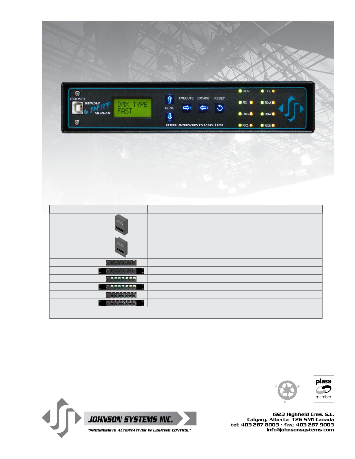
Model Description
DMX-6PIM 6-PORT Installation Merger for permanent hardwired installations
DMX-6PIM-FM Flush Mount version of DMX-6PIM above
DMX-6PM-XLR Portable 6-PORT Merger with 5 pin XLR connectors
DMX-6PM-XLR-RM 19" Rack Mount (1RU) 6-PORT Merger with 5 pin XLR connectors
DMX-6PM-TB
DMX-6PM-TB-RM
DMX-6PM-RJ45 Portable 6-PORT Merger with RJ45 “Ethercon” connectors
DMX-6PM-RJ45-RM 19" Rack Mount (1RU) Merger with RJ45 “Ethercon” connectors
* PC not included. Requires Windows. PowerTerm software not included.
Portable 6-PORT Merger with “break-away” terminal block DMX connectors
19"
Rack M
ount (1RU) 6-PORT Merger with “break-away” terminal block DMX connectors
JOHNSON SYSTEMS INC.
WWW.JOHNSONSYSTEMS.COM
O
R
F
T
I
T
E
!
R
E
S
U
E
R
E
C
Y
C
L
R
E
Page 2

O
R
F
T
I
T
E
R
E
S
U
E
!
R
E
C
Y
C
L
R
E
Contents
Introduction ......................................................................................................3
Characteristics .................................................................................................4
Drawings & Details ..........................................................................................4
Example Application Riser Diagrams ..............................................................6
Installation .......................................................................................................8
Mounting Options ............................................................................................8
Power Supply Input Connections ....................................................................9
DMX Input/Output Connections ....................................................................10
DMX-6PM Controller Board ...........................................................................13
User Interface ................................................................................................14
System Status • LED Indicators ....................................................................15
System Status • LCD Display ........................................................................15
Quick Programming Reference to System Conguration Menu Items ..........16
Detailed Programming of System Conguration Menu Items........................16
USB Tech Port Operation ..............................................................................19
Warranty
All DMX 6-PORT MERGER models come with a standard one (1) year
limited warranty. Extended warranties of up to ten (10) years are available at
the time of purchase.
For details visit www.johnsonsystems.com/warranties.htm
For Technical Assistance
1. Refer to your product user manual. The most current revision is
available online: www.johnsonsystems.com/literature.htm
2. Contact the “point-of-sale” dealer or distributor from which this product
was originally purchased, and ask for technical assistance.
3. If neither of the above can provide you with the necessary information,
please contact our factory via email ([email protected])
or phone (403-287-8003) during business hours (Monday to Friday,
8:00AM to 5:00PM MST).
2
WWW.JOHNSONSYSTEMS.COM
Page 3
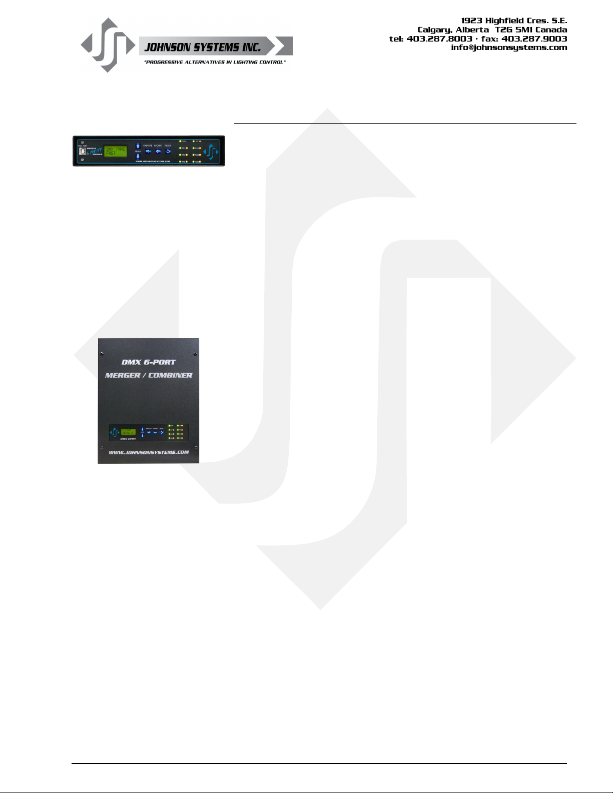
DMX 6-PM
DMX 6-PIM
Introduction
JSI’s DMX 6-PORT MERGER combines up to six DMX512 data lines
into one DMX512 universe. A cost-effective DMX input management
solution for temporary and hardwired installations requiring multiple
DMX sources or multiple opto-isolated DMX input locations.
Model variants include compact portable, 19" rack mount and
installation boxes for permanent installations. DMX I/O options include
RJ45, terminal block and 5-Pin XLR connector.
Input DMX data streams are combined in a “Highest Take
Precedence” (HTP) or “Pile On”. Multiple units can be cascaded
together for larger installations.
A USB “TECH PORT” interface (for use with a *PC) for ease of
monitoring DMX output level data on all 512 channels at one time.
Features
• Six DMX512 inputs, one DMX512 output.
• State-of-the-art design permits “real-time” DMX merging/
combining of all six DMX inputs at 44 packets per second.
• LCD display for easy setup and monitoring.
• Power and data receive LED indicators.
• DMX I/O options include RJ-45, terminal block
and 5 pin XLR connectors.
• USB “TECH PORT” for *PC monitoring of all DMX
inputs and output.
• Removable EEPROM module allows for ease
of rmware upgrade.
• Unique power saving standby (idle) mode reduces
power consumption to less than 1 Watt, a “green” power
management product.
• Keypad lockout prevents unauthorized access.
• Up to 10 year product warranty available.
WWW.JOHNSONSYSTEMS.COM 3
Page 4
Characteristics
• Power Supply Requirements
• DMX-6PM (all models) = 12VDC (adapter included).
• DMX-6PIM (installation version) = 90 to 264VAC, 47-63HZ, 1Ø 3 wire.
• Environment
• Temperature Range: 23°F (-5°C) to 104°F (40°C) ambient.
• Humidity Range: 0% to 90% non-condensing.
• Isolation
• 2,500 Vrms minimum per DMX input.
• Auto-resetting 240V polyswitch fusing of all DMX inputs and output.
• Physical
• DMX-6PM (All models) = 9" x 7" x 1.75" (23 cm x 18 cm x 4.4 cm).
• DMX-6PIM (Installation box version) = 9.5" x 12" x 3.4" (24 cm x 30 cm x 8.6 cm).
• DMX-6PIM-FM (Flush Mount cover for above) = 11.7" x 14.2" (30 cm x 36 cm).
• Weight
• DMX-6PM (Portable/table top version) = 3.6 lbs. (1.6 Kg).
• DMX-6PIM (Installation box version) = 7.4 lbs. (3.3 Kg).
• Material
• 18-gauge steel CRS.
• Finish
• Hammer texture black powder coat.
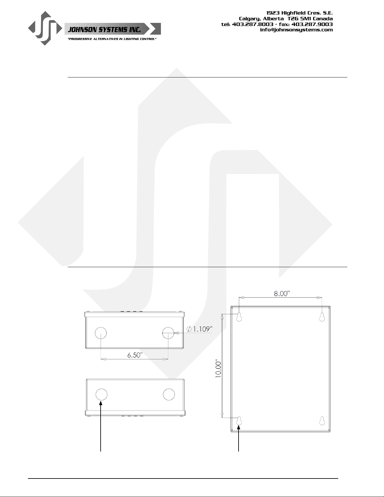
Drawings & Details
Models: DMX-6PIM, DMX-6PIM-FM
4
(4) Knockouts For Wire/Conduit Entry (4) Mounting Keyholes For 1/4" (6mm) Hardware
WWW.JOHNSONSYSTEMS.COM
Page 5
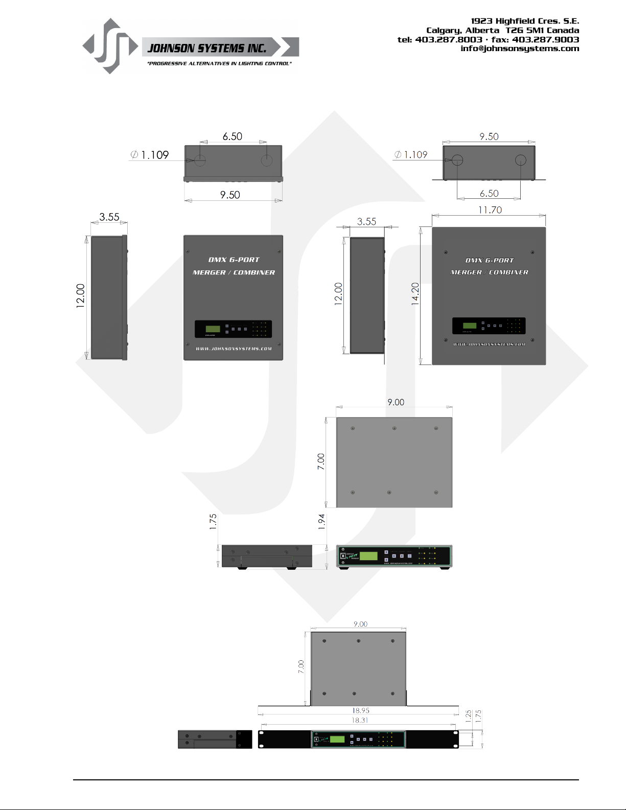
Model: DMX-6PIM Model: DMX-6PIM-FM
Model: DMX-6PM
Model: DMX-6PM-RM
WWW.JOHNSONSYSTEMS.COM 5
Page 6
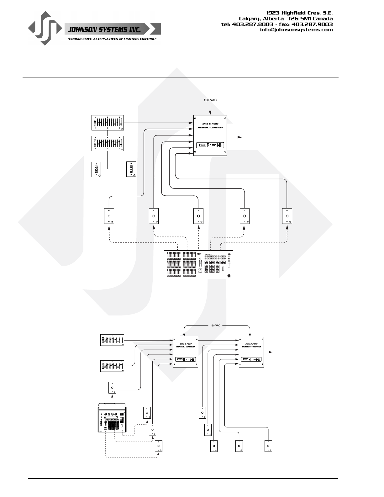
Example Application Riser Diagrams
Theatrical Example #1
Booth
House
Control
SMP
House
Control
Entrance Entrance
Booth SMP Stage
DMX IN DMX IN DMX IN DMX IN DMX IN
DMX IN #1
DMX IN #2
DMX IN #3
DMX IN #4
DMX IN #5
DMX IN #6
Right
WWW.JOHNSONSYSTEMS.COM
DMX Console
DMX OUT
Grid House
Center
Theatrical Example #2
Booth
House
Control
SMP
House
Control
Booth
DMX IN
Control
DMX
Console
6
SMP
WWW.JOHNSONSYSTEMS.COM
FOH
DMX IN
Down
Stage
Right
DMX IN
DMX IN #1
DMX IN #2
DMX IN #3
DMX IN #4
DMX IN #5
DMX IN #6
DMX IN
WWW.JOHNSONSYSTEMS.COM
Stage
DMX OUT
Up
DMX IN
Left
Grip
House
Right
DMX IN
DMX IN #1
DMX IN #2
DMX IN #3
DMX IN #4
DMX IN #5
DMX IN #6
House
Left
WWW.JOHNSONSYSTEMS.COM
Back
Of House
Center
DMX OUT
DMX INDMX INDMX IN
Page 7
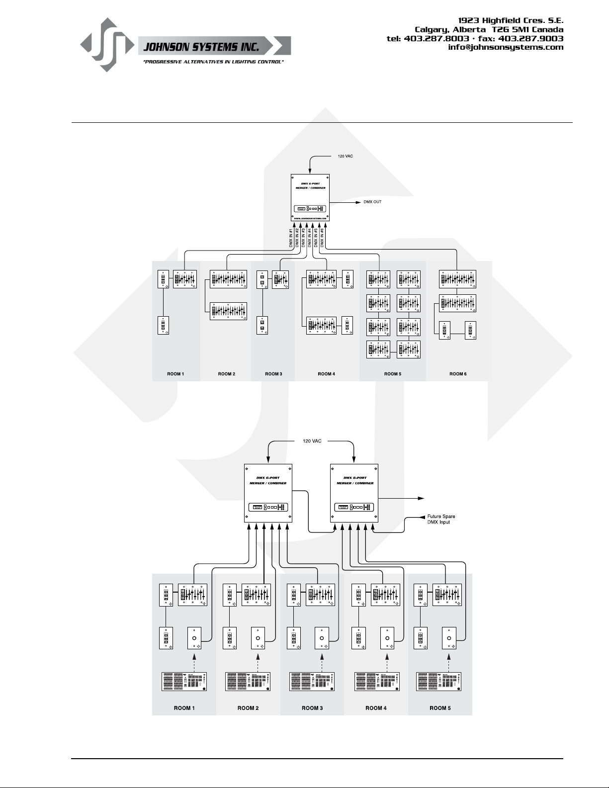
Example Application Riser Diagrams
Architetural Example #1
Architetural Example #2
DMX OUT
WWW.JOHNSONSYSTEMS.COM WWW.JOHNSONSYSTEMS.COM
DMX IN #1 DMX IN #6
DMX IN #1
DMX IN #2
DMX IN #3
DMX IN #4
DMX IN #5
DMX IN #6
DMX IN #2
DMX IN #3
DMX IN #4
DMX IN #5
DMX OUT
DMX INDMX INDMX INDMX INDMX IN
WWW.JOHNSONSYSTEMS.COM 7
Page 8
Installation
All DMX 6-PORT MERGER models are intended for indoor use only, in a
controlled environment at room temperature..
• Mount in a suitable location.
Refer to the Mounting Options section
on page 8 for applicable details.
• Connect the applicable power supply input.
Refer to the Power Supply Input Connections section
on page 9 for applicable details.
• Connect DMX inputs and output.
Refer to the DMX Input / Output Connections section
on page 10 for details.
• Program, setup, test and verify functionality.
Refer to the Detailed Programming of System Conguration Menu
Items section on page 16 for details.
• Optionally, monitor/view the DMX channel levels on a PC.
Refer to the USB Tech Port Operation section on page 19 for details.
WARNING: Type 1 enclosure for indoor use only!
Mounting Options
DMX 6-PORT MERGER models are capable of various mounting options to
suit the application required.
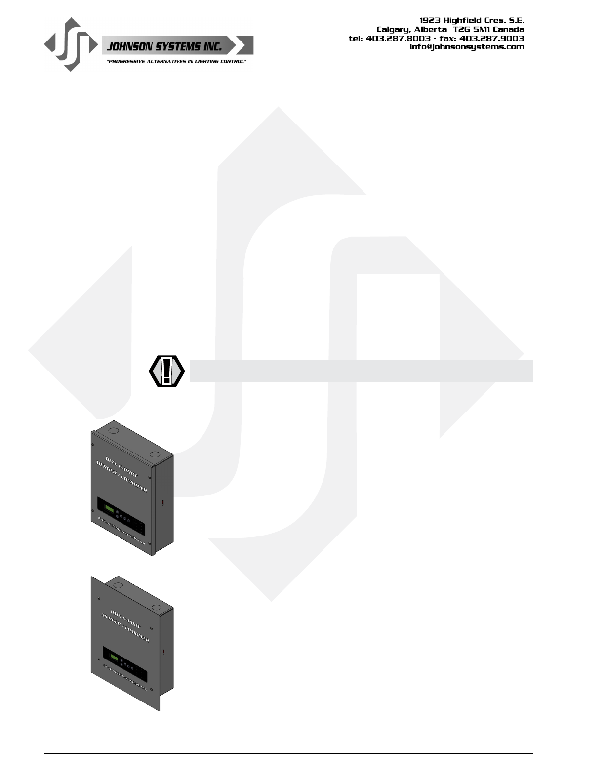
Model: DMX-6PIM
Mount to any wall surface located in a suitable location. Four 1/4" (6mm)
screws or bolts are required to fasten the enclosure safely to the wall (refer
to drawing for mounting locations and dimensions). To access the mounting
locations, simply remove the lid. The lid is secured by four (4) #6-32 x
3/8" machine screws. Use a #2 Philips screwdriver to remove the screws.
Be sure to save the screws to re-install the lid once installation is complete.
Model: DMX-6PIM-FM
Mount inside a studded (3.5" minimum depth) wall for a ush nish in a
suitable location. Four 1/4" (6mm) screws or bolts are required to fasten
the enclosure safely in the wall (refer to drawing for mounting locations and
dimensions). Alternatively, the enclosure may be mounted on the sides of
the enclosure to a single stud or two studs with 9.5" centers. When side
mounting the enclosure to studs, drill suitable mounting holes in the sides
of the enclosure. When drilling holes on the side(s) of the enclosure, be
sure to protect the internal electronics and clean out all metal lings. The
lid is secured by four (4) #6-32 x 3/8" machine screws. Use a #2 Philips
screwdriver to remove the screws. Be sure to save the screws to re-install
the lid once installation is complete.
8
WWW.JOHNSONSYSTEMS.COM
Page 9
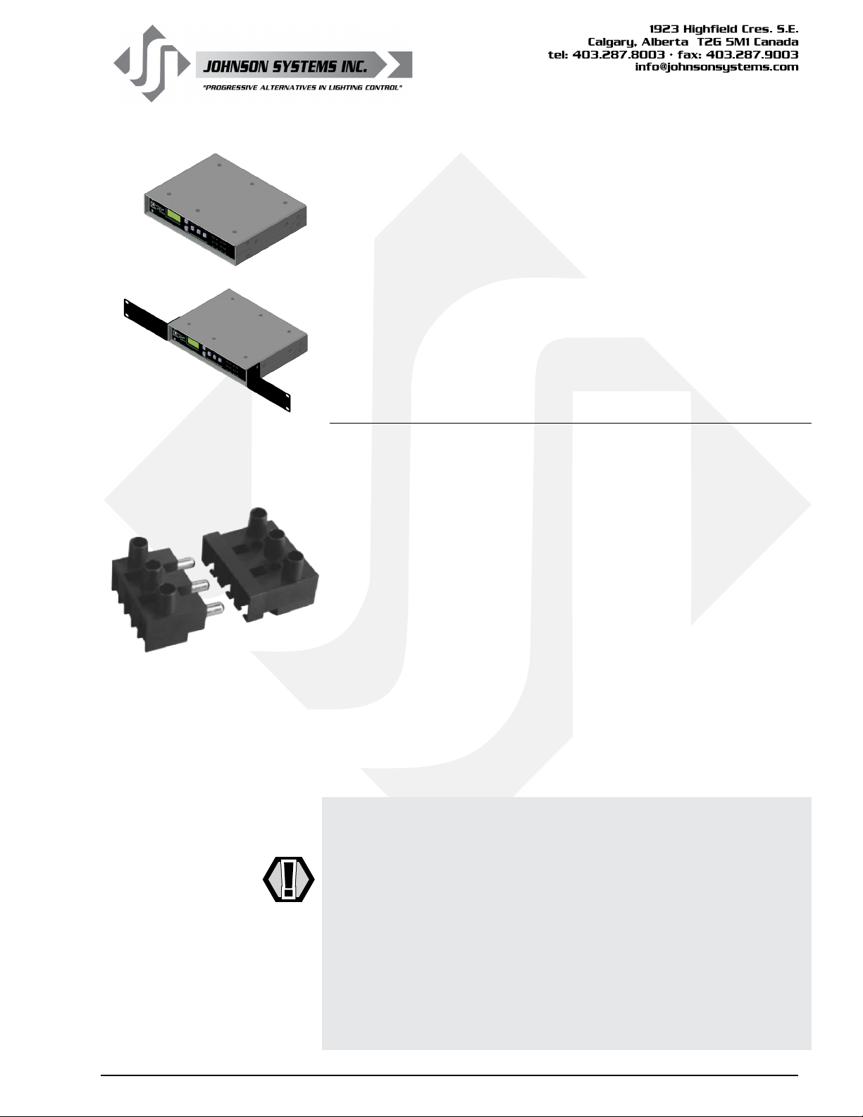
Models: DMX-6PM-XLR, DMX-6PM-TB, DMX-6PM-RJ45
For portable or permanent installation applications. Set on a at surface in
just about any indoor location. Rubber feet on the bottom of the enclosure
help keep the enclosure in place.
Models: DMX-6PM-XLR-RM, DMX-6PM-TB-RM, DMX-6PM-RJ45-RM
For 19" rack mount applications. Two (2) 19" rack mounting brackets are
provided. To install the brackets, use a #2 Philips screwdriver to remove the
four (4) (two (2) per side) mounting screws on the front-left side and frontright side, and fasten the brackets in place using the same mounting screws.
Install the unit in a 19" rack using standard rack mounting hardware (not
included).
Power Supply Input Connections
Models: DMX-6PIM, DMX-6PIM-FM
AC Power Supply Input: 100-240VAC, 1P3W, 20A (MAX), 50/60Hz.
With the lid removed, the AC power supply input termination area is located
at the top of the enclosure. A break-away style terminal block is provided for
the AC power supply input connections. Two (2) 1.109" knockouts (suitable
for 0.75" conduit) are located on the top of the enclosure. The top-left
knockout location is recommended for the AC wire (conduit) entry. Unplug
the terminal block to terminate the three (3) wires. Use a 1/8" athead
screwdriver to torque the power terminals to the specication provided below.
Once the wire termination is complete, plug the terminal block back in and
ensure it is fully seated. Verify all wiring terminations and secure the lid
before powering up.
• AC power supply connections: HOT (LINE), NEU (NEUTRAL),
GND (GROUND)
• Use wire size #18 to #12 AWG (stranded or solid core) copper wire only,
rated for 167°F (75°C) minimum.
• Strip insulation length to 0.25" (6.4mm).
• Torque power terminals (HOT, NEU, GND) to 4.5 IN-LBS (0.5 NM).
WARNING: AC power supply input requires an external disconnect
(circuit breaker)!
WARNING: AC wiring termination must be completed by qualied
personnel only!
WARNING: For connection use copper wire only, rated for
167°F (75°C) minimum.
WARNING: Ensure all AC power supply connections are tightened to
the torque specication provided, before turning on the AC
power supply!
WARNING: Ensure the enclosure lid is secure before turning on
the AC power supply!
WWW.JOHNSONSYSTEMS.COM 9
Page 10
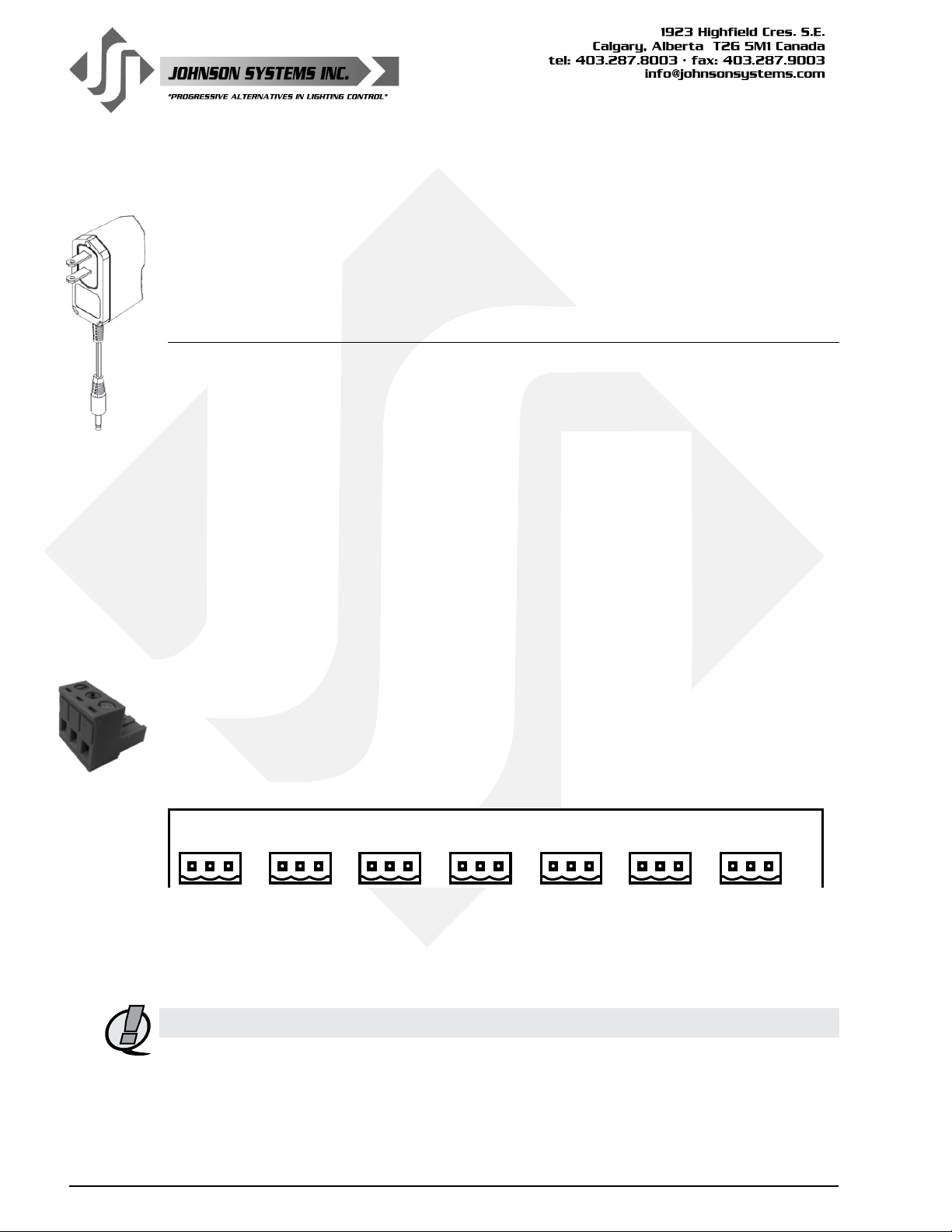
Models: DMX-6PM-XLR, DMX-6PM-TB, DMX-6PM-RJ45,
DMX-6PM-XLR-RM, DMX-6PM-TB-RM, DMX-6PM-RJ45-RM
DC Power Supply Input: 12VDC, 0.5A (MIN)
A “wall wart” type AC-DC power supply is provided. Plug the power supply into a standard
120VAC Edison (NEMA 5-15 or 5-20) receptacle and plug the center positive 12VDC 2.1mm
output plug into the jack located at the rear of the enclosure.
DMX Input/Output Connections
All DMX 6-PORT MERGER models are equipped with six (6) DMX input ports and one (1) DMX
output port. All DMX inputs are terminated and must be the last (end-of-line) DMX receiving
device in the daisy-chain topology. The DMX output is terminated as per the USITT DMX512-A
protocol.
• Complies with USITT DMX512-A (ANSI E1.11 - 2008), standard protocol for digital data
control.
• Recommended cable is Belden 9829, 9842, CAT 5 or equivalent
(low-capacitance, twisted pair).
• Wiring must follow a daisy-chain topology.
• Maximum of 32 receiving devices on a single DMX line.
• Maximum cable length is 1,500 feet (455 meters).
• For more information, Google DMX, or visit: http://old.usitt.org/DMX512FAQ.aspx
Models: DMX-6PIM, DMX-6PIM-FM
DMX is connected via 3-pin breakaway type connectors, located on the DMX-6PM controller
board. Two (2) 1.109" knockouts (suitable for 0.75" conduit) are located on the bottom of
the enclosure, and are the recommended locations for the DMX wire (conduit) entry. Unplug
the breakaway connector to terminate the three (3) wires. Use a 1/8" athead screwdriver to
torque the connector terminals to the specication provided below. Once the wire termination is
complete, plug the breakaway connector back in and ensure it is fully seated. Verify all wiring
terminations and secure the lid before powering up.
DMX IN 2DMX IN 3DMX IN 4DMX IN 5DMX IN 6DMX OUT
SHIELD/
COMMON
DATA-
SHIELD/
COMMON
DATA-
SHIELD/
COMMON
DATA-
SHIELD/
COMMON
DATA-
SHIELD/
COMMON
DATA-
SHIELD/
COMMON
DATA-
DATA+
DATA+
DATA+
DATA+
DATA+
DATA+
DMX IN 1
SHIELD/
COMMON
DATA-
DATA+
J2J3J4J5J6J7
J1
Breakaway Type Connector Wire Termination
• Strip insulation length to 0.3" (7.5mm).
• Torque connector terminals to 3.6 IN-LBS (0.4 NM).
• Be sure to isolate and protect all shield wires.
NOTE: For connection use copper wire only, rated for 167°F (75°C) minimum.
3-Pin Breakaway Type Connector Connection Details (Pinout)
10
• Pin 1 = DMX Shield / Common
• Pin 2 = DMX Data-
• Pin 3 = DMX Data+
WWW.JOHNSONSYSTEMS.COM
Page 11
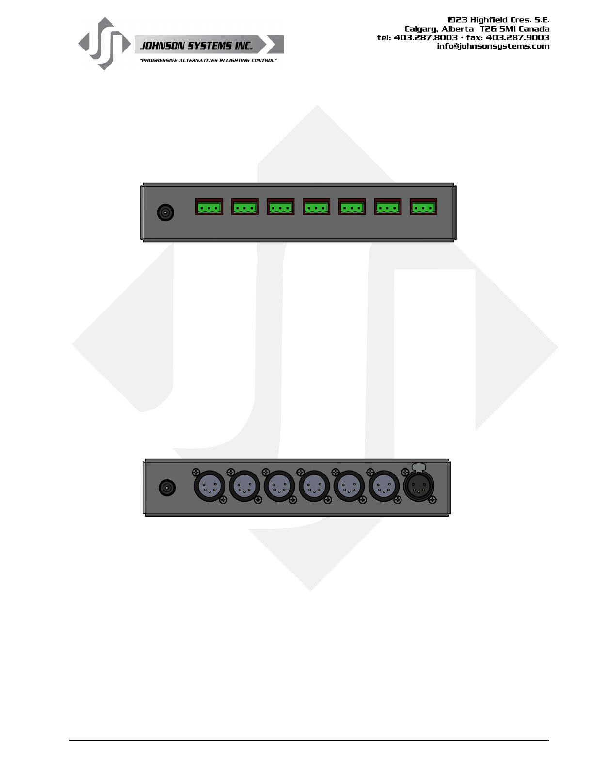
Models: DMX-6PM-TB, DMX-6PM-TB-RM
DMX is connected via 3-pin breakaway type connectors, located on the rear panel of the
enclosure. Unplug the breakaway connector to terminate the three (3) wires. Use a 1/8" athead
screwdriver to torque the connector terminals to the specication provided below. Once the wire
termination is complete, plug the breakaway connector back in and ensure it is fully seated.
Breakaway Type Connector Wire Termination
• Strip insulation length to 0.3" (7.5mm).
• Torque connector terminals to 3.6 IN-LBS (0.4 NM).
• Be sure to isolate and protect all shield wires.
3-Pin Breakaway Type Connector Connection Details (Pinout)
• Pin 1 = (SH) DMX Shield / Common
• Pin 2 = (D-) DMX Data-
• Pin 3 = (D+) DMX Data+
Models: DMX-6PM-XLR, DMX-6PM-XLR-RM
DMX is connected via 5-pin XLR type connectors, located on the rear panel of the enclosure.
There are six (6) male connectors for the DMX inputs and one (1) female connector for the DMX
output. Before connecting, ensure the DMX cable complies with industry standards.
5-Pin XLR Connection Details (Pinout)
Pin 1 = DMX Shield / Common
Pin 2 = DMX DataPin 3 = DMX Data+
Pin 4 = Not Used / No Connection
Pin 5 = Not Used / No Connection
WWW.JOHNSONSYSTEMS.COM 11
Page 12
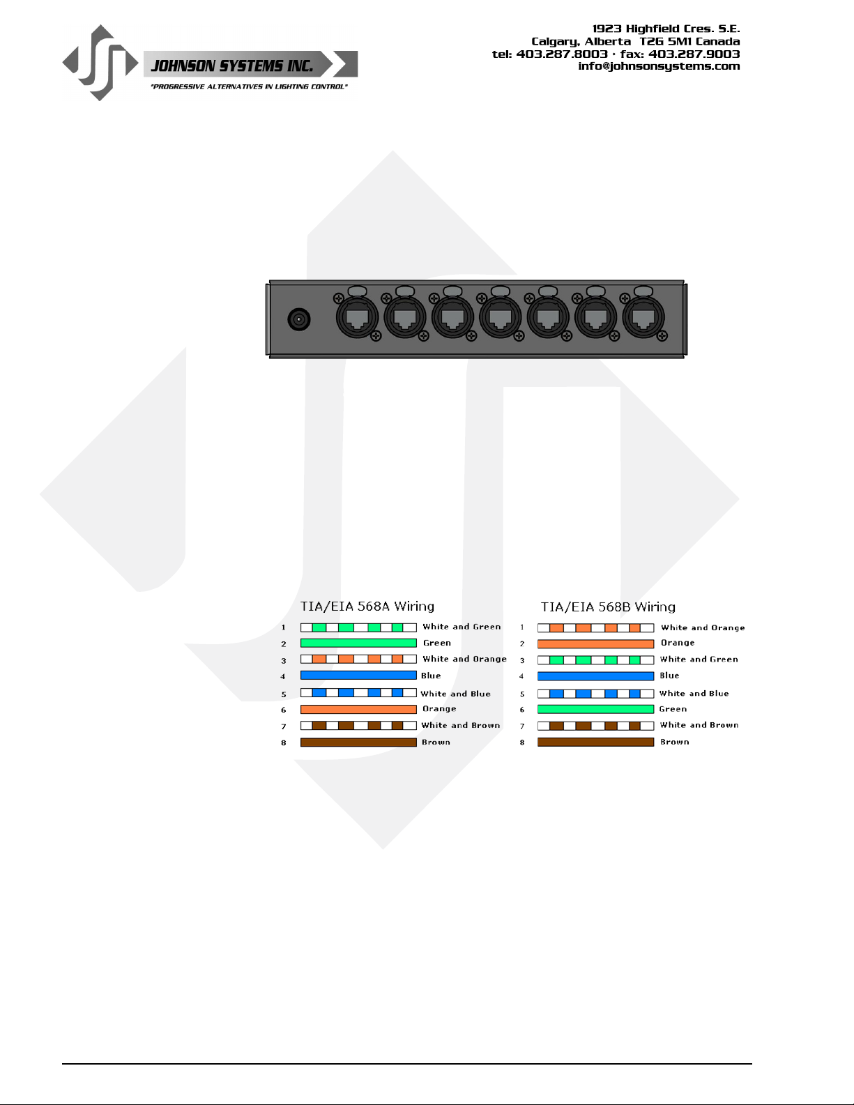
Models: DMX-6PM-RJ45, DMX-6PM-RJ45-RM
DMX is connected via RJ45 (etherCON) type connectors, located on the rear
panel of the enclosure. There are seven (7) female connectors for the DMX
inputs and output. For connection, use conventional Ethernet cables (CAT5 or
CAT5e) terminated in either EIA/TIA 568A or 568B wiring standards. Neutrik
etherCON cable connectors may be installed to lock the connectors in place.
RJ45 Connection Details (Pinout)
Pin 1 = DMX Data+
Pin 2 = DMX DataPin 3 = Not Used / No Connection
Pin 4 = Not Used / No Connection
Pin 5 = Not Used / No Connection
Pin 6 = Not Used / No Connection
Pin 7 = DMX Shield / Common
Pin 8 = DMX Shield / Common
12
WWW.JOHNSONSYSTEMS.COM
Page 13
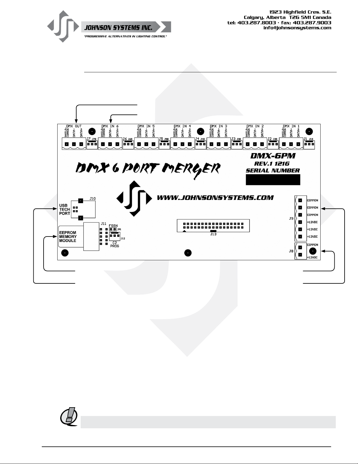
DMX-6PM Controller Board
The DMX-6PM controller board is the central electronic control system (aka brain) for all
DMX 6-PORT MERGER models.
(1) DMX Output Connector
(6) DMX Input Connectors
EEPROM Memory Module
USB Tech Port
+12VDC Power Supply Input Connector
+12VDC Power Supply Output Connector
+12VDC Power Supply Output for Models: DMX-6PIM, DMX-6PIM-FM
The AC-DC power supply located at the top of the enclosure is capable sourcing up to a total of
30 Watts (2.4 Amps) of power at 12VDC. Up to 24 Watts (2 Amps) may be used to power external
devices via the provided 6-pin breakaway type connector. Two (2) 1.109" knockouts (suitable for
0.75" conduit) are located on the bottom of the enclosure, and are the recommended locations
for the DC wire (conduit) entry. Unplug the breakaway connector to terminate the wires. Use a
1/8" athead screwdriver to torque the connector terminals to the specication provided below.
Once the wire termination is complete, plug the breakaway connector back in and ensure it is fully
seated. Verify all wiring terminations and secure the lid before powering up.
Breakaway Type Connector Wire Termination
• Terminate to +12VDC and COMMON on the J9 connector.
• Use wire size #28 to #12 AWG copper wire only, rated for 167°F (75°C) minimum.
• Strip insulation length to 0.3" (7.5mm).
• Torque connector terminals to 3.6 IN-LBS (0.4 NM).
NOTE: Ensure external devices do not exceed the maximum combined current draw of 2 Amps.
WWW.JOHNSONSYSTEMS.COM 13
Page 14
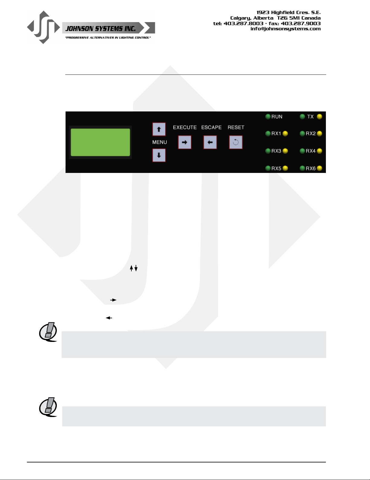
User Interface
All DMX 6-PORT MERGER models are equipped with a user interface located on the front
panel of the enclosure. The user interface provides access to all programming and conguration
settings. System status is easily visible on the LCD display and LED indicators.
LCD Display Programming Switches Status LED Indicators
All of the programming is accomplished using four (4) switches. Within a few minutes, most users
will nd the menu structure very intuitive and easy to navigate. All conguration settings are
automatically stored into an on-board EEPROM.
LCD Display
The LCD display is capable of displaying 2 lines of 8 Characters. A backlight automatically comes
on when activity is sensed on the switches. The LCD contrast can be easily adjusted for optimum
viewing. Refer to menu item “LCD VIEW” on page 18 for further details.
Programming Switches
The MENU UP/DOWN ( ) switches are used for navigating through the various system
conguration menu items. They also allow for programming of other specic parameters within
a selected menu. Pressing and holding either switch will speed up the scroll rate, which can be
helpful to speed up the conguration time.
The EXECUTE ( ) switch is normally used to select/enter a menu item, advance forward within
a selected menu item, or toggle between parameters within a selected menu item.
The ESCAPE ( ) switch is normally used to back up within a selected menu item one step at a
time or exit the menu completely.
14
NOTE: The programming switches can be locked out to prevent inadvertent conguration
changes. To toggle between “LOCKED!!” and “UNLOCKED” press and hold down the
EXECUTE and then ESCAPE switches at the same time for 4-5 seconds.
The RESET switch has two purposes. First, it allows for quick exit from a menu item after a
programming change and automatically puts the system into normal run mode. Second, it
provides a soft reboot for the systems microcontroller.
The programming switches are backlit with blue LED’s. The LED’s automatically turn on when
activity is sensed.
NOTE: A detailed procedure for programming all system conguration menu items can be found
on pages 16 to 18.
WWW.JOHNSONSYSTEMS.COM
Page 15

System Status • LED Indicators
RUN (Green)
Illuminates when the system is powered on and the microcontroller
is functioning normally.
RX1, RX2, RX3, RX4, RX5, RX6 (Green and Yellow)
The green LED illuminates when the DMX input port is powered on and the
isolated power supply is functioning normally. The yellow LED illuminates
when valid DMX is received and ashes when invalid DMX is received.
TX (Green and Yellow)
The green and yellow LED’s illuminate when any of the DMX input ports
are powered on and the system is transmitting DMX.
System Status • LCD Display
The top line of the LCD display shows the system is a DMX “6-PORT”
MERGER, unless the system conguration menu items are being accessed.
The bottom line of the LCD display shows the number of valid DMX inputs
being received and merged (“MERGE 0” thru “MERGE 6”), unless the system
conguration menu items are being accessed, or abnormal system status is
detected and displayed as follows:
RTC ERR!
Displayed when the system detects a runtime counter (RTC) error. This
occurs when there is an invalid hard-key code, and the runtime counter
is greater than 2160 hours (90 days). Refer to menu item “HARD-KEY”
on page 17 for further details.
USB ERR!
Displayed when the Tech Port is enabled and connected to a PC with
the terminal emulator running, and then a USB error occurs. When using
the Tech Port to monitor DMX via a PC, be sure to read and follow the
instructions included in the USB Tech Port Operation section starting
on page 19 of this manual.
LOCKED!
Displayed when an attempt is made to access the system conguration menu
items and the programming switches are locked out. To toggle between
“LOCKED!” and “UNLOCKED” press and hold down the “EXECUTE” and
then “ESCAPE” switches at the same time for 4-5 seconds.
WWW.JOHNSONSYSTEMS.COM 15
Page 16
Quick Programming Reference to System Configuration Menu Items
1. DMX TYPE Set the DMX output data rate to fast, medium or slow.
2. DMX PORT Turn the power on or off for each of the 6 DMX input ports.
3. TECHPORT Enable or disable the USB Tech Port used to monitor DMX via a PC.
4. RTIME View the total run time of the microcontroller.
5. HARD-KEY View the microcontroller’s unique eight-character hard-key code.
6. SERIAL# View the microcontroller’s unique eight-character silicone serial number.
7. VERSION View the microcontroller’s rmware version.
8. EEPROM View the type of EEPROM memory module plugged in.
9. FW-LOAD Load rmware into the microcontroller via the EEPROM memory module.
10. LCD VIEW Adjust the contrast of the LCD Display for optimum viewing.
Detailed Programming of System Configuration Menu Items
NOTE: The programming switches can be locked out to prevent inadvertent conguration
changes. To toggle between “LOCKED!!” and “UNLOCKED” press and hold down the
EXECUTE and then ESCAPE switches at the same time for 4-5 seconds.
The sequence of the following system conguration menu items appear as the MENU DOWN ( ) switch
is pressed. Pressing the MENU UP ( ) switch will sequence the system conguration menu items in the
opposite order. Pressing and holding either of the MENU UP/DOWN ( ) switches will speed up the scroll
rate, which can be helpful to speed up the conguration time.
1. DMX TYPE Set the DMX output data rate to fast, medium or slow.
The DMX output data rate may be adjusted for compatibility with some older legacy
DMX equipment incapable of receiving the maximum DMX output data rate. If there
is a problem receiving DMX from the DMX 6-PORT MERGER, try adjusting the DMX
output data rate.
FAST is the maximum setting for the DMX output data rate, transmitting 44pps
(Packets Per Second). FAST is the factory default.
MEDIUM is the intermediate setting for the DMX output data rate, transmitting 37pps
(Packets Per Second).
SLOW is the minimum setting for the DMX output data rate, transmitting 30pps
(Packets Per Second).
FAST Press EXECUTE to toggle the DMX output data rate to FAST.
MEDIUM Press EXECUTE to toggle the DMX output data rate to MEDIUM.
SLOW Press EXECUTE to toggle the DMX output data rate to SLOW.
Any change in the conguration is automatically saved.
2. DMX PORT Turn the power on or off for each of the 6 DMX input ports.
Each of the 6 DMX input ports may be powered off to conserve energy when DMX
input(s) are not connected or in use. Powering off DMX input port(s) may also be
used as a troubleshooting tool. When the DMX input port power is off, DMX can not
be received on the input. The corresponding green RX LED is illuminated when the
power is on and extinguished when the power is off. All 6 of the DMX input ports are
powered on by factory default.
Press EXECUTE to enter the menu.
IN 1 ON Displays the DMX input (IN 1) port and the power setting (ON).
IN 6 ON Press MENU ( ) to select the DMX input port from 1 to 6.
IN 6 OFF Press EXECUTE to toggle the power setting ON or OFF.
Any change in the conguration is automatically saved.
16
WWW.JOHNSONSYSTEMS.COM
Page 17
3. TECHPORT Enable or disable the USB Tech Port used to monitor DMX via a PC.
A USB Tech Port is provided on all DMX 6-PORT MERGER models. For models
DMX-6PM-XLR, DMX-6PM-TB, DMX-6PM-RJ45, DMX-6PM-XLR-RM, DMX-6PMTB-RM and DMX-6PM-RJ45-RM, the Tech Port is located on the front panel of the
enclosure. For models DMX-6PIM and DMX-6PIM-FM, the Tech Port is located on the
DMX-6PM controller board.
When using the Tech Port to monitor DMX via a PC, be sure to read and follow the
instructions included in the USB Tech Port Operation section starting on page 19 of
this manual.
DISABLED Press EXECUTE to toggle the Tech Port from DISABLED to ENABLED.
ENABLED Press EXECUTE to toggle the Tech Port from ENABLED to DISABLED.
Any change in the conguration is automatically saved.
4. RTIME View the total run time of the microcontroller.
The run time counter keeps track of the total time the microcontroller is powered up.
The maximum time is 99999 hours, 59 minutes, 59 seconds, or about 11.4 years.
System operation is not effected when the maximum run time is reached and can be
reset to zero at the factory.
RTIME SS Shows the number of seconds (SS) of run time.
HHHHH:MM Shows the number of hours (HHHHH) and minutes (MM) of run time.
5. HARD-KEY View the microcontroller’s unique eight-character hard-key code.
The DMX 6-PORT MERGER may be shipped with an invalid hard-key code of
00000000. A valid hard-key must be entered before the run time (RTIME) counter
reaches 2160 hours/90 days. If the run time expires without a valid hard-key the
LCD display will show a runtime counter error (RTC ERR!) and the DMX output
port transmits all zero level data, rendering it useless until a valid hard-key code
is entered. This feature can help to ensure full and timely payments for product
distributors.
HARD-KEY A dash (-) between HARD and KEY represents a valid hard-key.
HARD KEY A blank space between HARD and KEY represents an invalid hard-key.
XXXXXXXX Shows the unique eight-character hard-key code (XXXXXXXX).
DISABLED This menu is disabled to help prevent inadvertent changes.
DISABLED Follow the procedure below to enable the menu and modify the hard-key.
ENABLED Press and hold MENU ( ) and MENU ( ) at the same time for 4-5 seconds.
XXXXXXXX The cursor ( _ ) indicates the hard-key character being modied.
XXXXXXXX Press MENU ( ) to modify the hard-key character.
XXXXXXXX Press EXECUTE to advance within the menu, to the next hard-key character.
XXXXXXXX Press ESCAPE to back up within the menu, to previous hard-key character.
XXXXXXXX Repeat until all characters are modied to the desired (valid) hard-key code.
Press ESCAPE to exit the menu and save the desired hard-key code.
Press RESET to exit the menu without saving.
The menu will automatically timeout after 2 minutes of inactivity and save.
NOTE: Be sure to record and le the hard-key code for future reference.
6. SERIAL# View the microcontroller’s unique eight-character silicone serial number.
XXXXXXXX Shows the unique eight-character serial number.
7. VERSION# View the microcontroller’s software version.
VER X.X Shows the microcontroller’s software version.
WWW.JOHNSONSYSTEMS.COM 17
Page 18

8. EEPROM View the type of EEPROM memory module plugged in.
An EEPROM memory module is not installed on DMX 6-PORT MERGER products.
If a rmware update is required, Johnson Systems Inc. may supply an EEPROM
memory module with the latest rmware version. A rmware (F) type EEPROM is
used to update the current rmware version running on the DMX-6PM microcontroller
to the rmware version saved on the EEPROM.
NO MEM ! Indicates the EEPROM memory module is not installed.
6PORT-F Indicates the EEPROM type is programmed for rmware (F) operation.
VER X.X Press EXECUTE to display the version (VER) of the rmware.
DISABLED Press EXECUTE and the menu feature is disabled for factory use only.
9. FW-LOAD Load rmware into the microcontroller via the EEPROM memory module.
If a rmware update is required, Johnson Systems Inc. may supply an EEPROM
memory module with the latest rmware version. The rmware EEPROM memory
module must be inserted into EEPROM memory module port located on the DMX-
6PM controller board, and the rmware can then be loaded into the microcontroller.
Press EXECUTE to enter the menu.
DISABLED This menu is disabled for inadvertent use. Proceed to enable.
ENABLED Press and hold MENU ( ) and MENU ( ) at the same time for 4-5 seconds.
MEMCHECK Automatically checks the EEPROM memory module for rmware type.
CRC-TEST Automatically does a CRC test on the rmware code in the EEPROM.
>>>>>>>> CRC test in progress.
VER X.X Displays the rmware version on the EEPROM memory module.
UPDATE?? Press EXECUTE to proceed.
SURE ??? Press EXECUTE to proceed.
UPDATING Firmware update in progress.
WILL Firmware update in progress.
AUTO Firmware update in progress.
RESTART Firmware update in progress.
PLEASE Firmware update in progress.
WAIT.... When update is complete the RUN LED ashes and system restarts.
NO MEM! Displayed if an EEPROM memory module is not detected.
WRONG Displayed if wrong type (parameter) EEPROM memory module is detected.
MEM TYPE Displayed if wrong type (parameter) EEPROM memory module is detected.
WRONG Displayed if wrong product type of EEPROM memory module detected.
PRODUCT Displayed if wrong product type of EEPROM memory module detected.
CRC ERR! Displayed if CRC test fails and the EEPROM memory module is defective.
18
WARNING: Do not reset or turn the power off while the rmware is being
updated. Doing so will cause unrecoverable loss of rmware
data that is being loaded into the DMX-6PM microcontroller.
10. LCD VIEW Adjust the contrast of the LCD Display for optimum viewing.
Press EXECUTE to enter the menu.
ADJUST Press MENU ( ) to adjust the LCD contrast.
Press ESCAPE to exit the menu and save the desired LCD view.
Press RESET to exit the menu without saving.
The menu will automatically timeout after 2 minutes of inactivity and save.
WWW.JOHNSONSYSTEMS.COM
Page 19
USB Tech Port Operation
The Tech Port is used to connect to a PC via USB. Emulation software
such as PowerTerm® may be used to monitor/view the DMX channel levels
received on each of the DMX input ports, as well as the DMX channel levels
transmitted on the DMX output port. Other diagnostics such as status, packet
size, packet rate can also be viewed.
PowerTerm® Lite is the PC emulation software recommended by the factory.
Other software that emulates VT52 may be used, but is not advised or
supported in this manual.
PowerTerm® Lite Specications: http://www.ericom.com/specs/Lite_Plus.pdf
Buy PowerTerm® Lite Online: https://www.ericom.com/BuyNow/default.asp
Once PowerTerm® Lite has been downloaded and installed on a PC,
it is very important to set it up correctly to communicate with the host
DMX 6-PORT MERGER.
NOTE: Johnson Systems Inc. is not responsible for any PC related
problems! In no event shall Johnson Systems Inc. be liable for any
direct, indirect, incidental, special, exemplary, or consequential
damages (including, but not limited to, procurement of substitute
goods or services; loss of use, data, or prots; or business
interruption) however caused and on any theory of liability, whether
in contract, strict liability, or tort (including negligence or otherwise)
arising in any way out of the use of this software, even if advised of
the possibility of such damage.
NOTE: Use of the Tech Port is recommended for procient PC users only!
USB Tech Port Connection and Disconnection Procedure
NOTE: Ensure the DMX 6-PORT MERGER menu item TECHPORT
is set to DISABLED. If TECHPORT is set to ENABLED before
communications is established with the terminal emulator, it will lock
up the PC and may require a reboot. Be extremely diligent in the
connection and disconnection procedure.
Connection Procedure:
1. Ensure the DMX 6-PORT MERGER menu item TECHPORT
is set to DISABLED.
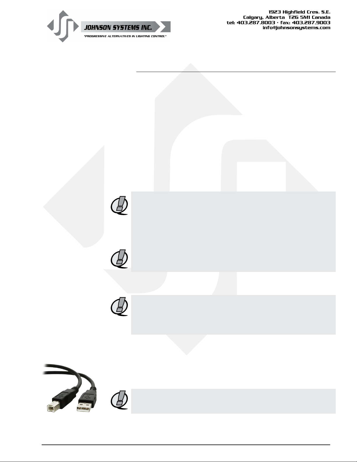
2. Use a standard USB A type male to B type male cable (printer
cable) to connect the Tech Port to a USB connector on the PC
(USB Cable not included).
NOTE: To establish communication between the DMX 6-PORT MERGER
and PC, the correct USB driver needs to be installed on the PC.
Refer to the USB Driver Information section on page 23 for details.
WWW.JOHNSONSYSTEMS.COM 19
Page 20
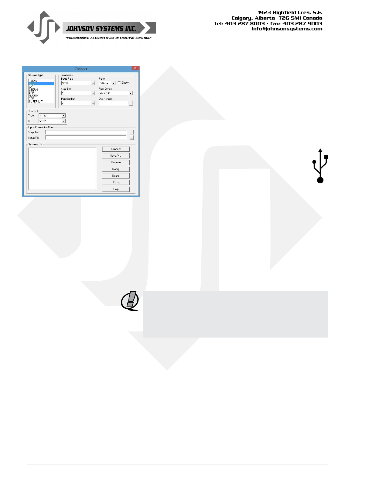
3. Open PowerTerm® Lite on the PC.
The “Connect” window automatically pops up when
PowerTerm® is rst opened. Alternatively, select the
“Communication” menu tab and click “Connect”. Set “Session
Type” to “COM” and “Terminal Type” to “VT 52”. In the
“Parameters” area, the only important setting is the “Port
Number” (all other settings within the “Parameters” area are
ineffective). Be sure the correct “Port Number” is selected.
If unsure of the “Port Number”, refer to point 7 of the
USB Driver Information section on page 23.
Click “Connect” to continue.
4. On the DMX 6-PORT MERGER, go to menu item
TECHPORT and set to ENABLED. A hybrid USB
symbol appears on the top line of the LCD display
to indicate valid communication between the DMX
6-PORT MERGER and PowerTerm® Lite on the PC.
5. Monitor/view the DMX channel levels received on each of
the DMX input ports, as well as the DMX channel levels
transmitted on the DMX output port. Other diagnostics such
as status, packet size, packet rate can also be viewed.
• Press the “R” key to refresh the screen.
• Press the “1” key to view the DMX input port 1 levels.
• Press the “2” key to view the DMX input port 2 levels.
• Press the “3” key to view the DMX input port 3 levels.
• Press the “4” key to view the DMX input port 4 levels.
• Press the “5” key to view the DMX input port 5 levels.
• Press the “6” key to view the DMX input port 6 levels.
• Press the “7” key to view the DMX output port levels.
• Press the “U” key to toggle the units displayed (Percent,
Hexadecimal or Decimal).
NOTE: For suitable viewing, some setup is required. Refer to the
PowerTerm® Lite Terminal Setup Information section
on page 21 for details.
20
NOTE: Once viewing is complete, be sure to disconnect from the
session properly as indicated below.
Disconnection Procedure:
6. On the DMX 6-PORT MERGER, go to menu item
TECHPORT and set to DISABLED.
7. On PowerTerm® Lite, select the “Communication” menu tab
and click “Disconnect”.
8. Close PowerTerm® Lite on the PC.
9. Disconnect the USB cable from the Tech Port and PC.
WWW.JOHNSONSYSTEMS.COM
Page 21
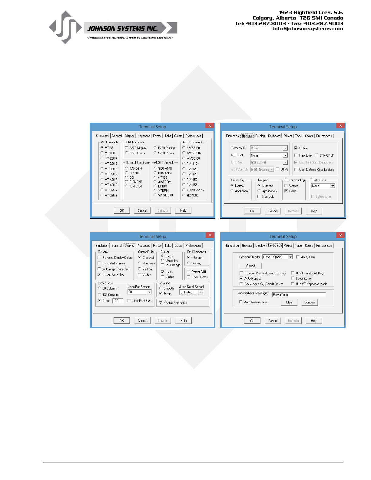
PowerTerm® Lite Terminal Setup Information
For suitable viewing, some setup is required.
On PowerTerm® Lite, select the “Terminal” menu tab and click “Setup”. The “Terminal Setup”
window pops up, and the following settings should be congured for each of the tabs:
Emulation General
Display Keyboard
WWW.JOHNSONSYSTEMS.COM 21
Page 22
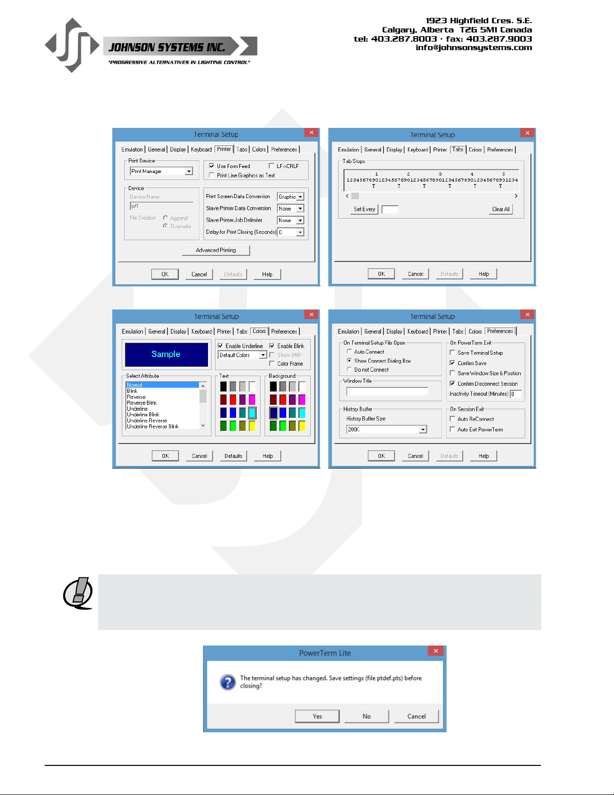
Printer Tabs
Colors Preferences
22
Important Pointers:
• Most tabs will not require modication but should be veried.
• In the “Display” tab, set the “Dimensions” to “Other 100”.
• In the “Display” tab, set the “Lines Per Screen” to “30”.
• In the “Display” tab, set the “Cursor” to “Block”.
• In the “Colors” tab, set the prefered colors.
NOTE: The Terminal Setup only needs to be completed once. When Terminal Setup is complete,
save the conguration settings. Selecting the “File” menu tab and click “Save Terminal
Setup As…” and name and save the le in a convenient location. Alternatively, when
PowerTerm® Lite is closed it will prompt to save changes.
WWW.JOHNSONSYSTEMS.COM
Page 23
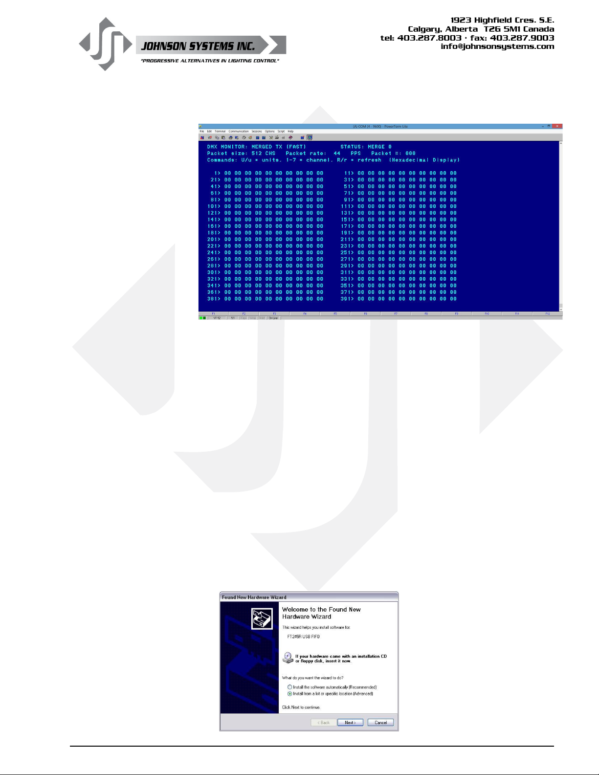
PowerTerm® Lite Screenshot
USB Driver Information
When the USB Tech Port is rst connected to a PC, the PC will automatically try to
nd a driver. It is unlikely to nd a driver automatically, so the applicable USB driver
will need to be downloaded and installed.
The USB interface chip (FT245R USB FIFO) on the DMX-6PM controller board is
manufactured by FTDI (Future Technology Devices International) and requires an
FTDI driver loaded on the same PC as the PowerTerm® Lite software.
The driver type required is VCP (Virtual COM Port). The VCP driver makes the USB
device appear as though it is connected to a COM port.
1. Select the applicable driver to download from the following link:
http://www.ftdichip.com/Drivers/VCP.htm
The driver download is a ZIP archive folder named: CDM 2.08.28 WHQL
Certied. Save it in a convenient location.
2. Create a folder in a convenient location (recommend C:\FTDI Driver), and
extract the ZIP archive folder contents to the newly created folder.
3. Connect the USB Tech Port to the PC. The “Found New Hardware Wizard”
automatically pops up. Select the “Install from a list or specic location
(Advanced)” option and click “Next” to continue.
WWW.JOHNSONSYSTEMS.COM 23
Page 24
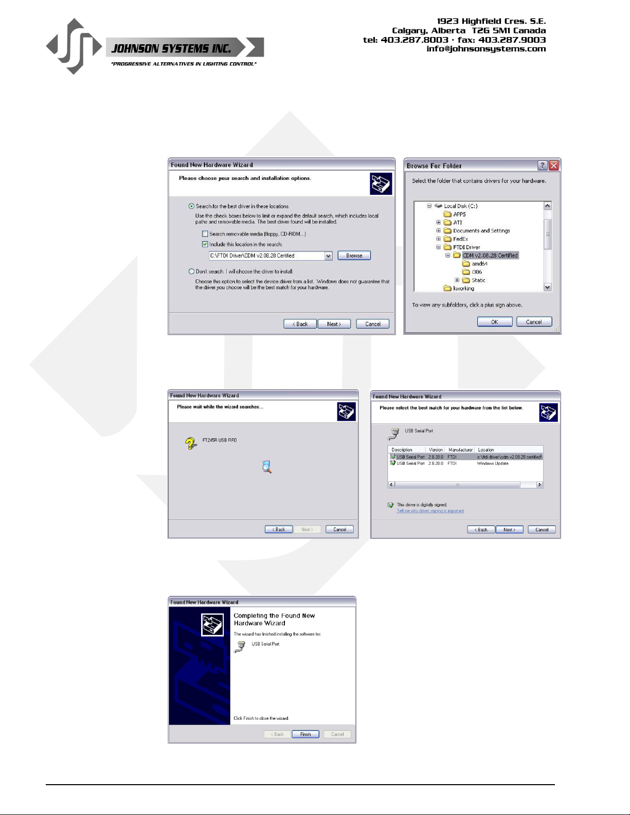
4. Select the “Search for the best driver in these locations” and “Include this location in
the seach” options and click “Browse” to continue. Select the le folder created in step
2. Once the folder is selected (highlighted), click “OK” and then “Next” to continue.
5. Be patient. It can take several minutes for the PC to nd the driver. Once the driver is
found, ensure the correct le path is selected (highlighted) and click “Next” to continue.
24
6. Once the PC completes the driver installation, click “Finish” to continue.
WWW.JOHNSONSYSTEMS.COM
Page 25
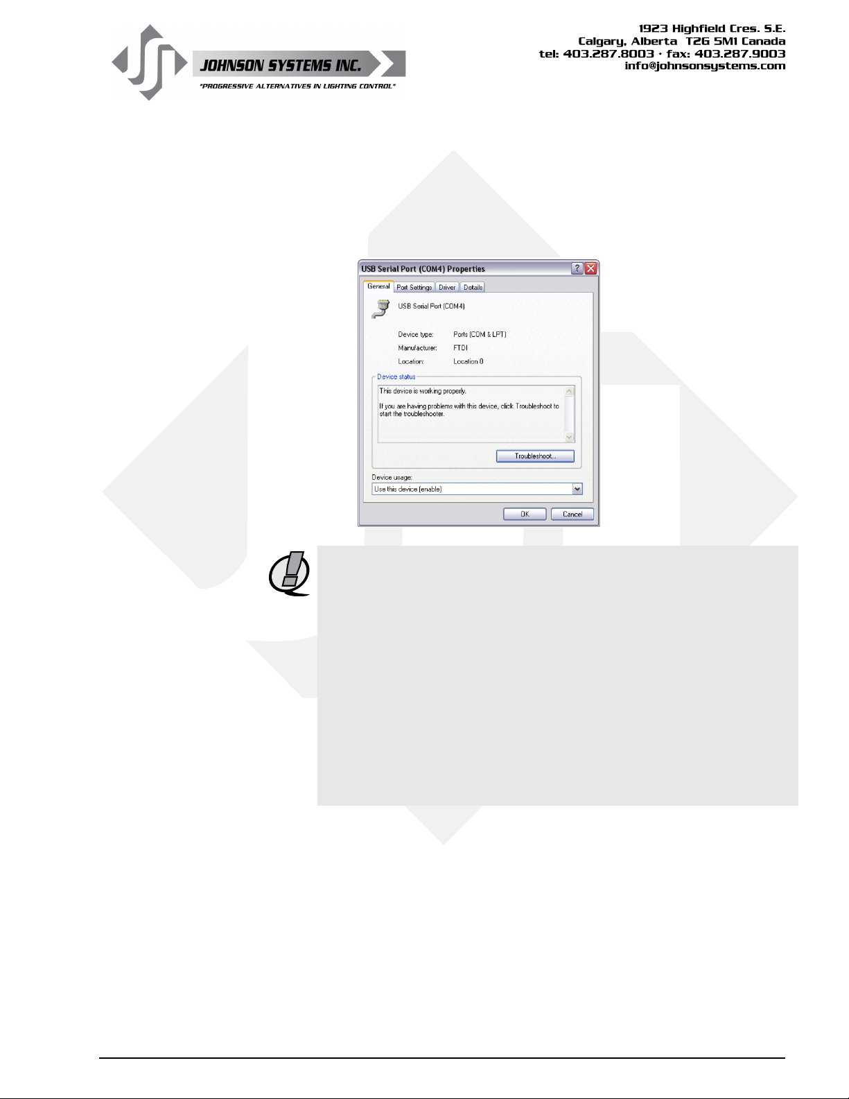
7. Open Device Manager. Under the “Ports (COM & LPT)” devices,
locate and select (double click) the “USB Serial Port (COM#)” the Tech
Port is plugged into. In the “General” tab, verify the “Manufacturer:
FTDI” and status “This device is working properly.” Note/record the
COM port number indicated as it is required for the terminal emulator
PowerTerm®.
NOTE: Johnson Systems Inc. (JSI) echoes the important note provided
by Future Technology Devices International Limited (FTDI)
regarding their driver software:
“This software is provided by Future Technology Devices International
Limited “as is” and any express or implied warranties, including, but not
limited to, the implied warranties of merchantability and tness for a
particular purpose are disclaimed. In no event shall Future Technology
Devices International Limited be liable for any direct, indirect, incidental,
special, exemplary, or consequential damages (including, but not limited to,
procurement of substitute goods or services; loss of use, data, or prots; or
business interruption) however caused and on any theory of liability, whether
in contract, strict liability, or tort (including negligence or otherwise) arising in
any way out of the use of this software, even if advised of the possibility of
such damage.”
WWW.JOHNSONSYSTEMS.COM 25
Page 26

User Manual
DMX 6-PORT MERGER
Rev. 1
WWW.JOHNSONSYSTEMS.COM
O
R
F
T
I
T
E
R
E
S
U
!
R
E
C
Y
E
C
L
R
E
 Loading...