

Page 1
CombiLine - CombiBlocHorti
Circulation pumps
INSTRUCTION MANUAL
CL-CBH/EN (1901) 7.6
Orginal instructions
Read and understand this manual prior to operating or servicing this product
Page 2

Page 3

EC Declaration of conformity
(Directive 2006/42/EC, appendix II-A)
Manufacturer
SPX Flow Technology Assen B.V.
Dr. A.F. Philipsweg 51
9403 AD Assen
The Netherlands
hereby declares that all pumps member of productfamilies CombiBloc, CombiBlocHorti,
CombiChem, CombiLine, CombiLineBloc and CombiNorm whether delivered without
drive (last position of serial number = B), or delivered as an assembly with drive (last
position of serial number = A), are in conformity with the provisions of Directive 2006/
42/EC (as altered most recently) and where applicable the following directives and
standards:
• EC directive 2014/35/EU, "Electric equipment for use within certain voltage limits"
• standards EN-ISO 12100 part 1 & 2, EN 809
The pumps to which this declaration refers may only be put into operation after they have
been installed in the way prescribed by the manufacturer, and, as the case may be, after
the complete system of which these pumps form part, has been made to fulfil the
requirements of Directive 2006/42/EC (as altered most recently).
EC Declaration of conformity
(Directive 2009/125/EC, Annex VI and Commission Regulation (EU) No 547/2012)
(Implementing Directive 2009/125/EC of the European Parliament and of the Council
with regard to ecodesign requirements for water pumps)
Manufacturer
SPX Flow Technology Assen B.V.
Dr. A.F. Philipsweg 51
9403 AD Assen
The Netherlands
Hereby declares that all listed pumps member of product families CombiBloc,
CombiBlocHorti, CombiChem, CombiLine, CombiLineBloc and CombiNorm are in
conformity with the provisions of Directive 2009/125/EC and Commission Regulation
(EU) No 547/2012 and the following standard:
• EN 16480
EC-ECO/EN (1712) 1.3 1
Page 4

Declaration of incorporation
(Directive 2006/42/EC, appendix II-B)
Manufacturer
SPX Flow Technology Assen B.V.
Dr. A.F. Philipsweg 51
9403 AD Assen
The Netherlands
hereby declares that the partly completed pump (Back-Pull-Out unit), member of
productfamilies CombiBloc, CombiBlocHorti, CombiChem, CombiLine, CombiLineBloc
and CombiNorm is in conformity with the following standards:
• EN-ISO 12100 parts 1 & 2, EN 809
and that this partly completed pump is meant to be incorporated into the specified pump
unit and may only be put into use after the complete machine of which the pump under
consideration forms part has been made and declared to comply with that directive.
Assen, December 1st 2017
B. Peek,
Managing Director
2 EC-ECO/EN (1712) 1.3
Page 5

Instruction manual
All technical and technological information in this manual as well as possible drawings
made available by us remain our property and shall not be used (otherwise than for the
operation of this pump), copied, duplicated, made available to or brought to the notice of
third parties without our prior written consent.
SPXFLOW is a global multi-industry manufacturing leader. The company's highlyspecialized, engineered products and innovative technologies are helping to meet rising
global demand for electricity and processed foods and beverages, particularly in
emerging markets.
Johnson Pump Horticulture
De Hondert Margen 23
2678 AC De Lier
The Netherlands
Tel. +31 (0)174 518410
Fax. +31 (0)174 518444
Copyright © 2015 SPXFLOW Corporation
INT Horti/EN (1512) 1.2 3
Page 6

4 INT Horti/EN (1512) 1.2
Page 7

CombiLine-CombiBlocHorti
Table of Contents
1 Introduction 9
1.1 Preface 9
1.2 Safety 10
1.3 Guarantee 10
1.4 Inspection of delivered items 10
1.5 Forwarding and storage instructions 11
1.5.1 Packaging 11
1.5.2 Opening the packaging 11
1.6 Ordering parts 11
2 General 13
2.1 Description of the pump 13
2.1.1 CombiLine (CL) 13
2.1.2 CombiBlocHorti (CBH) 13
2.1.3 General 13
2.2 Type code 13
2.3 Serial number 14
2.4 Applications 14
2.5 Construction 14
2.5.1 Pump casing CL 14
2.5.2 Pump casing CBH 14
2.5.3 Impeller 14
2.5.4 Shaft sleeve 14
2.5.5 Lantern piece 14
2.5.6 Electric motor 15
2.6 Ecodesign Minimum Efficiency Requirements Water Pumps 15
2.6.1 Introduction 15
2.6.2 Implementing Directive 2009/125/EC 15
2.6.3 Energy Efficient Pump Selection 18
2.6.4 Scope of Implementing Directive 2009/125/EC 19
2.6.5 Product information 19
2.7 Re-use 21
2.8 Scrapping 22
3Installation 23
3.1 Safety 23
3.2 General 23
3.3 Accessories 23
3.4 Piping 23
3.5 Installing a CL pump 24
CL-CBH/EN (1901) 7.6 5
Page 8

3.6 Installing a CBH pump 24
3.7 Connecting the electric motor 24
4 Commissioning 25
4.1 Inspection 25
4.2 Commissioning 25
4.3 Pump in operation 25
5 Maintenance 27
5.1 Bearings 27
5.2 Mechanical seal 27
5.3 Environmental influences 27
5.4 Noise 27
5.5 Motor 27
5.6 Failures 28
6Faults 29
6.1 Faults and possible causes 29
6.2 Causes and possible solutions 30
7 Disassembly and assembly 33
7.1 General 33
7.1.1 Special tools 33
7.1.2 Back Pull Out-unit 33
7.2 Precautions 33
7.2.1 Switch off the electricity supply 33
7.2.2 Support of the piping 33
7.2.3 Liquid draining 33
7.3 Disassembly 34
7.3.1 Disconnecting the motor 34
7.3.2 Removing the pump 34
7.4 Replacing the wear ring CBH 34
7.4.1 Disassembly 34
7.4.2 Assembly 35
7.5 Disassembling the pump 35
7.5.1 Back Pull Out-unit 35
7.5.2 Impeller 36
7.5.3 Mechanical seal 37
7.5.4 Lantern piece 37
7.6 Disassembling the electric motor 38
7.6.1 Electric motor stator 38
7.6.2 Electric motor bearings 38
7.7 Assembly 39
7.8 Assembling the electric motor 39
7.8.1 Electric motor bearings 39
7.8.2 Electric motor stator 39
7.9 Assembling the pump 40
7.9.1 Mechanical seal 40
7.9.2 Impeller 40
7.9.3 Pull-out unit 41
8 Dimensions and weights 43
8.1 Weight 43
8.2 Dimensions CombiLine 4/4 and 5/4 43
8.3 Dimensions CombiLine ND6 44
6 CL-CBH/EN (1901) 7.6
Page 9

CombiLine-CombiBlocHorti
8.4 Dimensions CombiLine ND10 46
8.5 Dimensions CombiBlocHorti 49
9Parts 53
9.1 Ordering parts 53
9.2 Recommended spare parts 53
9.3 CombiLine with thread connections 54
9.4 CombiLine with flange connections 55
9.5 CombiBlocHorti 57
9.6 Electric motor 59
10 Technical data 61
10.1 Technical data pumps 61
10.2 Technical data electric motor 62
10.3 Tightening torques 63
10.4 Tightening torques CombiLine 4/4 and 5/4 63
10.5 Recommended liquid locking agents 63
10.6 Noise data 64
10.7 Hydraulic performance 65
10.7.1 Performance overviews CombiLine 65
10.7.2 Performance overviews CombiBlocHorti 67
10.8 Permitted forces and torques on the flanges for CombiBlocHorti 69
CL-CBH/EN (1901) 7.6 7
Page 10

8 CL-CBH/EN (1901) 7.6
Page 11

CombiLine-CombiBlocHorti
1 Introduction
1.1 Preface
This manual is intended for technicians and maintenance staff and for those who are in
charge of ordering spare parts
This manual contains important and useful information for the proper functioning and
maintenance of this pump. It also contains important instructions to prevent potential
accidents and damage, and to ensure safe and fault-free operation of this pump.
! Read this manual carefully before commissioning the pump. Familiarize
yourself with the operation of the pump and strictly obey the instructions!
The data published here comply with the most recent information at the time of going to
press. However they may be subject to later modifications.
SPXFLOW reserves the right to change the construction and design of the products at
any time without being obliged to change earlier deliveries accordingly.
This manual has been compiled by SPXFLOW with the utmost care. Nevertheless
SPXFLOW cannot guarantee the completeness of this information and therefore
assumes no liability for possible deficiencies in this manual. The buyer/user shall at all
times be responsible for testing the information and for taking possible additional and/or
deviating safety measures. SPXFLOW reserves the right to change the safety
instructions.
CL-CBH/EN (1901) 7.6 Introduction 9
Page 12

1.2 Safety
This manual contains instructions for working safely with the pump. Operators and
maintenance staff must be familiar with these instructions.
Installation, operation and maintenance has to be done by qualified and well prepared
personnel.
Below is a list of the symbols used for those instructions and their meaning:
Personal danger for the user. Strict and prompt observance of the
corresponding instruction is imperative.
! Risk of damage or poor operation of the pump. Follow the corresponding
instruction to avoid this risk.
➢ Useful direction or tip for the user.
1.3 Guarantee
SPXFLOW shall not be bound to any guarantee other than the guarantee accepted by
SPXFLOW. In particular, SPXFLOW will not assume any liability for explicit and/or
implicit guarantees such as but not limited to the marketability and/or suitability of the
articles supplied.
The guarantee will be cancelled immediately and legally if:
• service and/or maintenance has not been carried out strictly in accordance with the
instructions.
• necessary repairs have not been carried out by our personnel or have been carried out
without our prior written permission.
• the articles supplied have been changed without our prior written permission.
• the spare parts used are not original SPXFLOW parts.
• the products supplied are not used in accordance with their nature and/or purpose.
• the products supplied have been used amateurishly, carelessly, improperly and/or
negligently.
• the products supplied become defective due to external circumstances beyond our
control.
All parts which are liable to wear are excluded from guarantee.
Furthermore, all deliveries are subject to our "General conditions of delivery and
payment", which will be forwarded to you free of charge on request.
1.4 Inspection of delivered items
Check the consignment immediately on arrival for damage and conformity with the advice
note. In case of damage and/or missing parts, have a report drawn up by the carrier at
once.
10 Introduction CL-CBH/EN (1901) 7.6
Page 13

CombiLine-CombiBlocHorti
1.5 Forwarding and storage instructions
1.5.1 Packaging
The pump is packed in a solid cardboard box. The bigger types are provided with a
wooden bottom. The pump is bolted down on this bottom. The forwarding and storage
instructions are stated on the box by means of symbols. Adhere to these instructions.
Furthermore, the box contains the same information about the pump as the information
written on the label on the cover of this manual. Always leave the pump in the packaging
as long as possible in order to avoid damages and facilitate possible further transport in
case the pump has to be moved elsewhere. All boxes are provided with grips. Use these
grips as much as possible in case of manual transport.
For the bigger pump types, the wooden bottom is designed as a platform, allowing the
boxes to be moved by forklift.
! When using a forklift always set the forks as far apart as possible and lift the
package with both forks to prevent it from toppling over! Avoid jolting the
pump when moving it!
1.5.2 Opening the packaging
The boxes are kept shut by 2 plastic straps. These straps also serve to keep the bottom
and the covering box together.
Always make sure that the box stands on the floor! Wear gloves: the straps
are under tension and may be sharp!
1 Cut the plastic straps.
2 Remove the covering box.
3 Unscrew the pump from the bottom.
4 Rest the pump on the supporting brackets under the suction bend.
➢ Do not throw away the packaging! SPXFLOW is striving for an environmental minded
management. Please contact us about the possibilities of returning your packaging
materials.
1.6 Ordering parts
This manual contains a survey of the spare parts recommended by SPXFLOW as well as
the instructions for ordering them.
See http://www.spxflow.com/en/johnson-pump
➨ spare parts.
When ordering parts or for any correspondence you should always state all data
stamped on the name plate.
➢ This data is also printed on the label on the front of this manual.
If you have any questions or require further information with regard to specific subjects,
then do not hesitate to contact SPXFLOW.
➨ industries ➨ horticulture ➨ products
CL-CBH/EN (1901) 7.6 Introduction 11
Page 14

12 Introduction CL-CBH/EN (1901) 7.6
Page 15

CombiLine-CombiBlocHorti
2 General
2.1 Description of the pump
2.1.1 CombiLine (CL)
The CombiLine is a built-in in-line circulation pump range. These pumps are easy to
install in straight pipelines, inlet and outlet flange connections have the same size and
pattern and are positioned in-line.
2.1.2 CombiBlocHorti (CBH)
The CombiBlocHorti is a close-coupled foot-mounted pump range. These pumps are
characterised by a compact build and a pump casing with horizontal inlet and vertical
outlet.
2.1.3 General
CL and CBH share the same impeller, shaft seal, and drive section (Back-Pull-Out unit).
For this design the electric motor is provided with an extended, stainless steel motor
shaft. The impeller is directly mounted onto the motor shaft. The pumps are provided with
a rubber bellows mechanical seal, according to EN 12756 (DIN 24960).
The pumps are available with single- and double-speed electric motor. Frequency
controlled motor drives are available for the single-speed electric motors. These electric
motors are standard suitable for 50 Hz and 60Hz. The speed of the electric motor can be
controlled in a frequency range from 10 Hz - 60 Hz.
➢ Running the pump at the lower speed will result in considerable energy savings.
2.2 Type code
Pumps are available in various designs. The main characteristics of a pump are shown in
the type code.
Example: CL 100-160, CBH 100-160
CL CombiLine
CBH CombiBlocHorti
100
160 nominal impeller diameter in mm
diameter suction and delivery connection in mm (for CL)
diameter delivery connection in mm (for CBH)
CL-CBH/EN (1901) 7.6 General 13
Page 16
2.3 Serial number
Serial number of the pump or pump unit are shown on the name plate off the pump and
on the label on the cover of this manual.
Example: 19-001160
19 year of manufacture
001160 unique number
2.4 Applications
The CombiLine is a built-in circulation pump that can be used in the following areas:
• greenhouses
• hot and cold-water systems
• cooling-water systems
• utility building
• industrial installations
In general, this pump can be used for thin, clean or slightly polluted liquids. These liquids
should not affect the pump materials.
The maximum allowable temperature and pressure are mentioned in paragraph 10.1
"Technical data pumps".
Do not use the pump for purposes other than those for which it is delivered
without prior consultation with your supplier!
Using a pump in a system or under system conditions (liquid, pressure,
temperature, etc.) for which it has not been designed may hazard the user!
2.5 Construction
2.5.1 Pump casing CL
The pump casing is of the volute type. Suction and delivery flange are placed in-line and
have the same flange size. The specially shaped suction bend ensures low-noise
functioning of the pump.
2.5.2 Pump casing CBH
The pump casing is a volute type end-suction casing with horizontal inlet and vertical
outlet. A replaceable wear ring is fitted at the position of the impeller inlet.
2.5.3 Impeller
The impeller is of the closed type and is mounted directly on the end of the extended
motor shaft. The impeller is fixed by means of a cap nut, except for pump types
CL4/4 and CL5/4, which have a normal nut.
2.5.4 Shaft sleeve
For the smaller pump types the motor shaft is protected by a shaft sleeve to keep it from
getting into contact with the pumped liquid.
CL 4/4, CL 5/4 and all pumps fitted with a IEC 132 or IEC 160 size electric motor or
with a 6-pole motor are not provided with a shaft sleeve.
2.5.5 Lantern piece
The lantern piece connects the electric motor to the pump casing, serving at the same
time as pump cover. Inside the lantern piece there is a standard mechanical seal with
bellows, according to EN 12756.
14 General CL-CBH/EN (1901) 7.6
Page 17

CombiLine-CombiBlocHorti
2.5.6 Electric motor
The electric motor has an extended shaft, on which the impeller is mounted. The forces
on the impeller are absorbed by the motor bearings. The bearings are dust-proof and
greased for life, so they are maintenance-free. The protection class for all motors is IP
55. The electric motors are equipped as standard with an aluminium terminal box.
➢ All electric motors are suited for connection to frequency control.
2.6 Ecodesign Minimum Efficiency Requirements Water Pumps
• Directive 2005/32/EC of the European Parliament and of the Council;
• Commission regulation (EU) No 547/2012 Implementing Directive 2009/125/EC of
the European Parliament and of the Council with regard to ecodesign requirements for
water pumps.
2.6.1 Introduction
SPX Flow Technology Assen B.V. is an associate member of the HOLLAND PUMP
GROUP, an associate member of EUROPUMP, the organization of European pump
manufacturers.
Europump promotes the interest of the European pump industry with the European
institutions.
Europump welcomes the aim of the European Commission to reduce eco-impact of
products in the European Union. Europump is fully aware of the eco-impact of pumps in
Europe. For many years the ecopump initiative is one of the strategic columns in the work
of Europump. From the first of January 2013 the regulation is coming into force
concerning minimum required efficiencies of rotodynamic water pumps. The regulation
sets minimum efficiency requirements on water pumps set out under the Ecodesign
Directive for energy related products. This regulation mainly addresses manufacturers of
water pumps placing these products on the European market. But as a consequence
customers may also be affected by this regulation. This document gives necessary
information related to the coming into force of the water pump regulation EU 547/2012.
2.6.2 Implementing Directive 2009/125/EC
• Definitions:
“This Regulation establishes eco-design requirements for the placing on the market of
rotodynamic water pumps for pumping clean water, including where integrated in other
products.”
“Water pump” is the hydraulic part of a device that moves clean water by physical or
mechanical action and is of one of the following designs:
• End suction own bearing (ESOB);
• End suction close coupled (ESCC);
• End suction close coupled inline (ESCCi);
• Vertical multistage (MS-V);
• Submersible multistage (MSS);”
‘End suction water pump’ (ESOB) means a glanded single stage end suction
rotodynamic water pump designed for pressures up to 1600 kPa (16 bar), with a specific
speed ns between 6 and 80 rpm, a minimum rated flow of 6 m
power of 150 kW, a maximum head of 90 m with nominal speed of 1450 rpm and a
maximum head of 140 m with nominal speed of 2900 rpm;
‘End suction close coupled water pump’ (ESCC) is an end suction water pump of which
the motor shaft is extended to become also the pump shaft;
3
/h, a maximum shaft
CL-CBH/EN (1901) 7.6 General 15
Page 18

‘End suction close coupled inline water pump’ (ESCCi) means a water pump of which
the water inlet of the pump is on the same axis as the water outlet of the pump;
‘Vertical multistage water pump’ (MS-V) means a glanded multistage (i > 1) rotodynamic
water pump in which the impellers are assembled on a vertical rotating shaft, which is
designed for pressures up to 2500 kPa (25 bar), with a nominal speed of 2900 rpm and
a maximum flow of 100 m
3
/h;
‘Submersible multistage water pump’ (MSS) means a multistage (i > 1) rotodynamic
water pump with a nominal outer diameter of 4” (10,16 cm) or 6” (15,24 cm) designed to
be operated in a borehole at nominal speed of 2900 rpm, at operating temperatures
within a range of 0°C and 90°C;
This Regulation shall not apply to:
1 water pumps designed specifically for pumping clean water at temperatures below -
10°C or above +120°C;
2 water pumps designed only for fire-fighting applications;
3 displacement water pumps;
4 self-priming water pumps.
• Enforcement:
In order to enforce this there will be a Minimum Efficiency Index (M.E.I.) criteria set for
the above list of pumps.
The MEI is a dimensionless figure that is derived from a complex calculation based on
the efficiencies at BEP (Best Efficiency Point), 75% BEP & 110% BEP, and the specific
speed. The range is used so that manufacturers do not take an easy option of providing
good efficiency at one point i.e. BEP.
The value ranges from 0 to 1,0 with the lower value being less efficient, this provides the
basis of eliminating the less efficient pumps starting with 0,10 in 2013 (the lowest 10%)
and 0,40 (the lowest 40%) in 2015.
The MEI value of 0,70 is classed benchmark for the most efficient pumps in the market at
the time of developing the directive.
The milestones for the MEI values are as follows;
1 1st January 2013 all pumps shall have a minimum MEI value of 0,10;
2 1st January 2015 all pumps shall have a minimum MEI value of 0,40.
The most important point of this is that unless the pumps comply then they
will not be allowed to have a CE marking.
• Part Load Performance
It is common practice that pumps spend much of their time working away from their rated
duty, and efficiency can fall off rapidly below the 50% duty point, any scheme should take
account of this real life performance. However, manufacturers need a pump efficiency
classification scheme that makes it impossible to design pumps with a steep fall off in
efficiency either side of the BEP point in order to claim a higher efficiency than would be
typical of real life operation.
16 General CL-CBH/EN (1901) 7.6
Page 19
CombiLine-CombiBlocHorti
η
PumpnsQBEP
,η
BOTTOM
≥
nsn
N
Q
BEP
H
BEP
0.75
-------------------
×=
η
BOTTOM PL OL,–
x η
BOTTOM
⋅≥
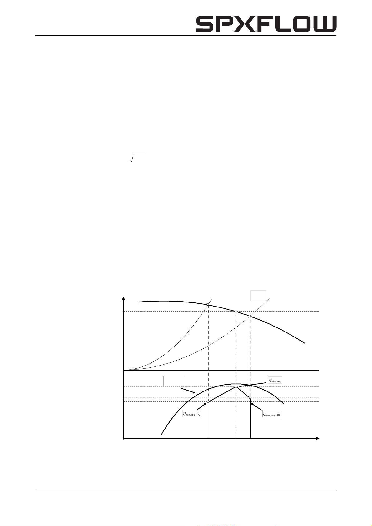
• ‘House of Efficiency’
The decision scheme ‘House of Efficiency’ takes into account design and application
purposes as well as the pump minimum efficiency dependence on flow. The minimum
acceptable efficiency is therefore different for each pump type. The pass-or-fail scheme
is based on two criteria A and B.
Criterion A is the pass-or-fail minimum efficiency requirement at the best efficiency point
(BEP) of the pump:
Where
Criterion B is the pass-or-fail minimum efficiency requirement at part load (PL) and at
overload (OL) of the pump:
Therefore a method is devised what is called a “house of efficiency” scheme that also
requires pumps to pass efficiency thresholds at 75% and 110% of rated flow. The
advantage of this is that pumps will be penalised for poor efficiency away from rated
efficiency, hence it will take account of real life pump duties.
It should be stated that while the scheme may appear complicated at first sight, in
practice it has been easy for the manufacturers to apply the scheme to their pumps.
Figure 1: House of Efficiency
Head
System
Curve
BEP
H
BEP
η
Pump Eff.
η
BEP
ηOL= 0.98 η
ηPL= 0.94
BEP
η
BEP
Curve
0
CL-CBH/EN (1901) 7.6 General 17
Q
PL
Q
Q
BEP
OL
Flow
Page 20
2.6.3 Energy Efficient Pump Selection
In selecting the pump, care should be taken to ensure that the duty point required is as
close as possible to the pump’s Best Efficiency Point (BEP). Different heads and flows
can be achieved by changing the diameter of the impeller and thereby eliminating
unnecessary energy loss.
The same pump can be offered at different motor speeds to allow the pump to be used
over a much wider range of duties. For instance, changing from 4-pole motor to 2-pole
motor will enable the same pump to deliver twice as much peak flow at 4 times the head.
Variable speed drives allow the pump to operate efficiently over a wide range of speeds
hence duties in an energy efficient manner. They are particularly useful in systems where
is a variation in required flow.
A very useful tool for energy efficient pump selection is the downloadable software
program “Hydraulic Investigator 2” from the SPXFLOW website.
Hydraulic Investigator is the selection guide for centrifugal pumps and search by pump
family and pump type starting from entering required capacity and head. Further refine
the pump curves to find the pump that meets your specification.
The default setting of applicable pump types is prioritized on highest efficiency. In the
standard automated selection procedure the optimum (trimmed) impeller diameter is
calculated already, where applicable. Manually the rotating speed can be adjusted as
well when a variable speed drive is preferred.
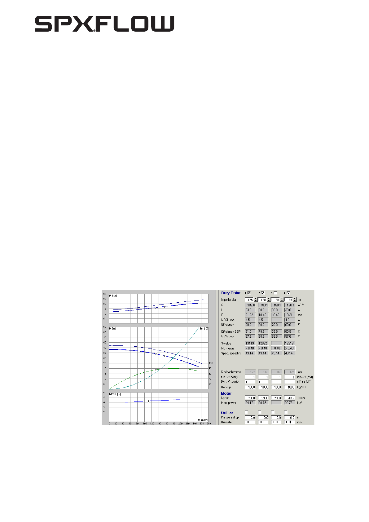
Example:
Curve 1: performance at maximum impeller diameter and 2960 rpm;
Curve 2: performance at required duty point (180 m
power consumption 18,42 kW;
Curve 4: performance at required duty point with maximum diameter and reduced
rotating speed (2812 rpm), power consumption 18,21 kW.
Figure 2: Hydraulic Investigator 2
3
/h, 30 m) with trimmed impeller,
18 General CL-CBH/EN (1901) 7.6
Page 21

CombiLine-CombiBlocHorti
2.6.4 Scope of Implementing Directive 2009/125/EC
The following SPX Flow Technology products are in the scope of the directive:
• CombiNorm (ESOB)
•CombiChem (ESOB)
•CombiBloc (ESCC)
•CombiBlocHorti (ESCC)
• CombiLine (ESCCi)
•CombiLineBloc (ESCCi)
The vertical multistage pump range MCV(S) is out of the scope of the directive, these
pumps are designed for pressures up to 4000 kPa (40 bar).
Submersible multistage pumps are not available in the SPXFLOW product portfolio.
2.6.5 Product information
Name plate, example:
Figure 3: Name plate horticulture
Johnson Pump Horticulture
De Hondert Margen 23
NL-2678 AC De Lier
CR Nr. 04029567
1
ØNo.
2
MEI
eff.
≥
3
45
Table 1: Name plate horticulture
1 CL 80-200 Product type and size
2 19-001160 Year and serial number
3 0,40 Minimum Efficiency Index at max. impeller diameter
4 [xx.x]% or [-,-]% Effciency for trimmed impeller diameter
5 202 mm Fitted impeller diameter
1 Minimum efficiency index, MEI:
Table 2: MEI value, CombiLine
Speed
[rpm]
Material Cast iron
4/4 1450 ---
4/4 2900 > 0,40
5/4 1450 > 0,40
5/4 2900 > 0,40
32-125 1450 > 0,40
40C-125 1450 > 0,40
40-160 1450 > 0,40
40-200 1450 > 0,40
50-125 1450 > 0,40
50-160 1450 > 0,40
50-200 1450 > 0,40
65-125 1450 > 0,40
65-160 1450 > 0,40
MEI value according
prEN16480
Remarks
Outside scope, Q < 6 m3/h
CL-CBH/EN (1901) 7.6 General 19
Page 22
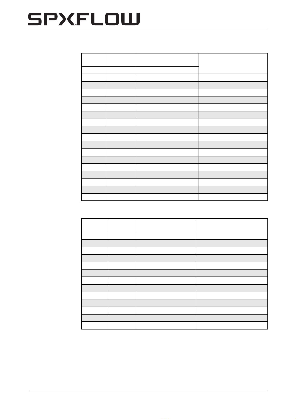
Table 2: MEI value, CombiLine
Speed
[rpm]
Material Cast iron
65-200 1450 > 0,40
80-125 1450 > 0,40
80-160 1450 > 0,40
80-200 1450 > 0,40
100-150 1450 > 0,40
100-160 1450 > 0,40
100-200 1450 > 0,40
80A-250 1450 > 0,40
125-160 1450 > 0,40
125C-200 1450 > 0,40
100A-250 1450 > 0,40
150-125 1450 --- Outside scope, ns > 80 rpm
150-160 1450 > 0,40
150-200 1450 > 0,40
125A-250 1450 > 0,40
150-250 1450 > 0,40
200-200 1450 > 0,40
MEI value according
prEN16480
Remarks
Table 3: MEI value, CombiBlocHorti
Speed
[rpm]
Material Cast iron
80C-200 1450 > 0,40
80-250 1450 > 0,40
100-160 1450 > 0,40
100C-200 1450 > 0,40
100C-250 1450 > 0,40
125-250 1450 > 0,40
150-125 1450 ---
150-160 1450 ---
150-200 1450 > 0,40
150-250 1450 > 0,40
200-200 1450 > 0,40
250-200 1450 > 0,40
2 The benchmark for most efficient water pumps is MEI ≥ 0,70.
3 Year of manufacture; the first 2 positions (= the last 2 positions of the year) of the
serial number of the pump as marked on the rating plate. An example and explanation
is given in paragraph 2.6.5 "Product information" of this document.
MEI value according
prEN16480
Remarks
Outside scope, ns > 80 rpm
Outside scope, ns > 80 rpm
20 General CL-CBH/EN (1901) 7.6
Page 23
CombiLine-CombiBlocHorti
4 Manufacturer:
SPX Flow Technology Assen B.V.
Registration number at Chamber of Commerce 04 029567
Johnson Pump Horticulture
De Hondert Margen 23
2678 AC De Lier
The Netherlands
5 Product type and size identifier are marked on the rating plate. An example and
explanation is given in paragraph 2.6.5 "Product information" of this document.
6 The hydraulic pump efficiency of the pump with trimmed impeller diameter is marked
on the rating plate, either the efficiency value [xx.x]% or [-.-]%.
7 Pump curves, including efficiency characteristics, are published in the downloadable
software program “Hydraulic Investigator 2” from the SPXFLOW website. For
downloading “Hydraulic Investigator 2” go to http://www.spxflow.com/en/johnsonpump/resources/hydraulic-investigator/ The pump curve for the delivered pump is
part of the related customer order documentation package separate from this
document.
8 The efficiency of a pump with a trimmed impeller is usually lower than that of a pump
with the full impeller diameter. The trimming of the impeller will adapt the pump to a
fixed duty point, leading to reduced energy consumption. The minimum efficiency
index (MEI) is based on the full impeller diameter.
9 The operation of this water pump with variable duty points may be more efficient and
economic when controlled, for example, by the use of a variable speed drive that
matches the pump duty to the system.
10 Information relevant for disassembly, recycling or disposal at end-of-life is described
in paragraph 2.7 "Re-use", paragraph 2.8 "Scrapping" and chapter 7 "Disassembly
and assembly".
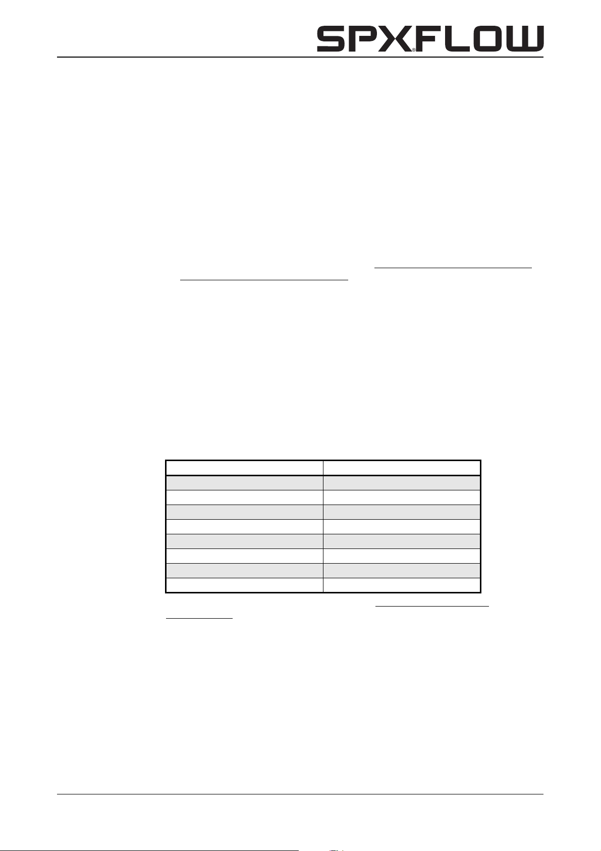
11 The benchmark efficiency Fingerprint Graphs are published for:
MEI = 0,40 MEI = 0,70
ESOB 1450 rpm ESOB 1450 rpm
ESOB 2900 rpm ESOB 2900 rpm
ESCC 1450 rpm ESCC 1450 rpm
ESCC 2900 rpm ESCC 2900 rpm
ESCCi 1450 rpm ESCCi 1450 rpm
ESCCi 2900 rpm ESCCi 2900 rpm
Multistage Vertical 2900 rpm Multistage Vertical 2900 rpm
Multistage Submersible 2900 rpm Multistage Submersible 2900 rpm
Benchmark efficiency graphs are available under http:\\www.europump.org/
efficiencycharts.
2.7 Re-use
The pump may only be used for other applications after prior consultation with
SPXFLOW or your supplier. Since the previously pumped medium is not always known,
the following instructions should be observed:
1 Flush the pump properly.
2 Make sure the flushing liquid is discharged safely (environment!)
Take adequate precautions and use the appropriate personal protection
means like rubber gloves and spectacles!
CL-CBH/EN (1901) 7.6 General 21
Page 24

2.8 Scrapping
If it has been decided to scrap a pump, the same flushing procedure as described in
paragraph 2.7 "Re-use" should be followed.
22 General CL-CBH/EN (1901) 7.6
Page 25

CombiLine-CombiBlocHorti
3Installation
3.1 Safety
• Read this manual carefully before installing the pump and putting it into operation.
Non-observance of these instructions may cause serious damage to the pump that is
not covered by our guarantee terms. Follow the instructions step by step.
• Depending on the design the pumps are suitable for liquids with a temperature of up
to 140°C. When installing the pump unit to work at 65°C and above the user should
ensure that appropriate protection measures and warnings are fitted to prevent
contact with the hot pump parts.
3.2 General
• The area in which the pump unit is to be placed should be adequately ventilated. A too
high ambient temperature and air humidity, as well as a dusty environment may have a
negative effect on the functioning of the electric motor.
• The foundation for a CBH pump must be hard, level and flat.
• The cooling air inlet of the motor should be positioned in such a way that unobstructed
air supply is ensured.
• Make sure that the system pressure is always below the maximum allowable
operational pressure. For exact values see paragraph 10.1 "Technical data pumps".
• If the pumped liquid is harmful to men or the environment, take appropriate measures
to drain the pump safely. Possible leakage liquid from the mechanical seal should also
be discharged safely.
3.3 Accessories
• In case the pump is provided with an isolation, special attention has to be paid To
temperature limits of shaft seal and bearing.
3.4 Piping
As regards the piping and connecting points of the pump attention should be paid to the
following:
• The piping to the suction and delivery connections must fit exactly and must not be
subject to stress during operation. For the maximum allowable forces and moments on
the pump flanges of a CBH pump see paragraph 10.8 "Permitted forces and torques
on the flanges for CombiBlocHorti".
• Preferably a CL pump should be mounted in the piping in such a way that the direction
of flow is vertical, so as to prevent air from remaining in the pump. Air in the pump may
cause damage to the mechanical seal!
• Make sure that the system has one or more draining apertures. Also, it should be
possible to bleed or de-aerate the system, preferably directly above the pump.
CL-CBH/EN (1901) 7.6 Installation 23
Page 26

• If necessary mount valves before and after the pump. Do not use quick-acting valves,
as they may cause high pressure impulses in the pump and the piping (water hammer
pressure).
• Before installing the pump, all piping should be flushed, to eliminate all dirt, grease or
possible other particles.
3.5 Installing a CL pump
The pump can be mounted in both horizontal and vertical piping. However, the electric
motor should always be in horizontal position.
When installing this type of pump, proceed as follows:
1 Make sure the piping is supported before and after the pump (brackets).
2 The arrow on the pump casing shows the exact position of the suction and delivery
flange.
3 Check the position of the terminal box on the electric motor in relation to the position
of the pump in the piping. If this position is not correct, the stator should be rotated.
See paragraph 7.6.1 "Electric motor stator".
4 Mount the flange gaskets and place the pump between the flanges of the piping.
5 Insert the fastening bolts and nuts for each flange and tighten them crosswise.
3.6 Installing a CBH pump
When installing this type of pump, proceed as follows:
1 Mount the flange gaskets and place the pump between the flanges of the piping.
2 In case of permanent arrangement of the pump, level the pump on the foundation by
means of shims.
3 Then carefully tighten the nuts of the foundation bolts.
4 Insert the fastening bolts and nuts for each flange and tighten them crosswise.
3.7 Connecting the electric motor
The electric motor must be connected to the mains by an approved
electrician, according to the locally prevailing regulations of the electricity
company.
• Refer to the instruction manual belonging to the electric motor.
• If possible, mount a working switch as close as possible to the pump.
24 Installation CL-CBH/EN (1901) 7.6
Page 27

CombiLine-CombiBlocHorti
4 Commissioning
4.1 Inspection
Prior to commissioning the pump:
• Check if the fuses have been installed.
• Check if the impeller can rotate freely. Do this by rotating the shaft end with a
screwdriver through the hole in the protective cover of the electric motor.
• Check if the suction and delivery connections have been mounted correctly.
• Check the sense of rotation.
4.2 Commissioning
Proceed as follows, both for commissioning and after the pump is put back into
operation after repairs:
1 Open the valves. If there still is hot water in the pipes, open the valves gradually to
prevent pressure impulses or sudden changes of temperature, which would cause
serious damage to the pump.
2 Fill the system with liquid until the correct pressure is reached.
3 Bleed the system.
4 Switch on the pump.
4.3 Pump in operation
When the pump is in operation, pay attention to the following:
! The pump should never run dry!
• Never use a stop valve in the suction line to control pump output. The stop valve
should always be fully opened during operation.
• Check whether the pressure difference between suction and delivery side
corresponds with the specifications of the pump's duty point.
• Check whether the absolute inlet pressure is sufficient, to prevent vaporization in the
pump. Vaporization may cause cavitation.
! Cavitation should always be prevented since it causes serious damage to the
pump!
CL-CBH/EN (1901) 7.6 Commissioning 25
Page 28

26 Commissioning CL-CBH/EN (1901) 7.6
Page 29

CombiLine-CombiBlocHorti
5 Maintenance
! Flawed maintenance will result in shorter lifespan, possible break down and
in any event loss of warranty.
5.1 Bearings
Both motor bearings have been greased for their lifetime and require no maintenance.
5.2 Mechanical seal
A mechanical seal generally requires no maintenance, however, it should never be
allowed to run dry. If there are no problems, do not dismantle the mechanical seal. As
the seal faces have run in on one another dismantling usually implicates replacement of
the mechanical seal. If a mechanical seal shows any leakage it has to be replaced.
5.3 Environmental influences
• When a unit is out of operation and there is a risk of freezing, it is recommended to
drain the unit.
• Check motor for accumulation of dust or dirt, which might influence motor
temperature.
• The standard protection class of the electric motor is IP 55, this means that it is
'spray-water proof'.
! Never spray water on hot pump elements! They may burst and hot water may
flow out.
5.4 Noise
The noise produced by a pump depends to a great extent on the operation conditions.
The values are stated in paragraph 10.6 "Noise data".
If a pump starts making excessive noise, this may point to certain problems with the
pump unit. A crackling noise can indicate cavitation or excessive motor noise can
indicate deterioration of the bearings.
5.5 Motor
Check motor specifications for start-stop frequency.
CL-CBH/EN (1901) 7.6 Maintenance 27
Page 30

5.6 Failures
1 If the pump shows problems, the cause may be elsewhere in the system. First check
whether this is the case.
2 If you are sure the problem is within the pump, try to determine the cause. See
chapter 6 "Faults". Then take the necessary measures.
3 See chapter 7 "Disassembly and assembly" in case repair is necessary.
Always switch off the pump and close the valves before trying to determine a
failure!
! First of all try to find what caused the failure. In case of electric failure, the
cause may be in the cabling. In that case consult a approved electrician!
28 Maintenance CL-CBH/EN (1901) 7.6
Page 31

CombiLine-CombiBlocHorti
6Faults
Faults in a pump system can have various causes. The fault may not be in the pump, it
may also be caused by the pipe system or the operating conditions. Firstly, always check
that installation has been executed in accordance with the instructions in this manual and
that the operating conditions still correspond with the specifications for which the pump
was purchased.
6.1 Faults and possible causes
1 Pump delivers no liquid: see C, D, G, I, K
2 Pump does not reach the working point: see A, B, D, E, G, H, I, L
3 Irregular liquid flow: see D, G, I
4 Pump leaks liquid: see M, N
5 Pump makes noise: see A, D, G, J, O, P
6 Pump vibrates: see J, O, P
7 Motor gets hot: see A, J, O
8 Thermal breakdown of pump: see E, J, K, O, P, Q, R
9 Pump got stuck: see F, I, J, K, O, P, R
CL-CBH/EN (1901) 7.6 Faults 29
Page 32

6.2 Causes and possible solutions
A Electrical connection is faulty:
• Consult your electrician
B Wrong sense of rotation:
• Consult your electrician
C Pump not filled with liquid:
•Open valves
• Fill pump with fluid
• De-aerate the system
D NPSH available too low:
• Increase the pre-pressure
• Mount the pump as low as possible in the piping
E Pump does not run at the required speed:
• Consult your electrician
F Foreign particles inside the pump:
• Dismantle and clean the pump
• If necessary mount a filter
G Air in the pipes:
• De-aerate the system
• Increase the immersion depth of the suction pipe
• Increase the liquid level at the suction side
H Required head higher than calculated:
• Change the speed
• Select another pump
I Suction pipe or possibly mounted filter blocked:
• Clean filter and suction pipe
J Damaged bearings:
• Replace bearings
• Inspect the shaft
• Check whether the impeller is not damaged
KImpeller stuck:
• Try to rotate the shaft at the rear by means of a screw driver through the hole in the fan
protecting cover
• Dismantle and clear the pump, check the shaft on straightness
30 Faults CL-CBH/EN (1901) 7.6
Page 33

CombiLine-CombiBlocHorti
L Suction valve is not entirely open:
• Open the valve
M Defective mechanical seal:
• Dismantle the pump and replace the mechanical seal
N O-ring faulty:
• Dismantle the pump and replace the O-ring
O Bent shaft:
• Dismantle the pump. Replace shaft, mechanical seal and impeller
P Damaged impeller:
• Dismantle the pump and replace the impeller
Q Temperature of the liquid too high:
• Check liquid temperature
R Overloaded motor:
• Check whether the cooling of the electric motor is not obstructed
• Consult your electrician
CL-CBH/EN (1901) 7.6 Faults 31
Page 34

32 Faults CL-CBH/EN (1901) 7.6
Page 35

CombiLine-CombiBlocHorti
7 Disassembly and assembly
7.1 General
7.1.1 Special tools
Special tools can make certain operations easier. The instructions will indicate when
these tools should be used.
7.1.2 Back Pull Out-unit
The pump is designed with a Back Pull Out-system. This means that in case of repairs,
the pump casing does not have to be removed from the piping (unless the fault is in the
pump casing itself).
7.2 Precautions
Before the pump can be repaired it first has to be removed from the system. Take the
following steps:
7.2.1 Switch off the electricity supply
1 Disconnect the electricity supply to the pump by setting the pump switch on the
switchboard or, if available, the operation switch, to "O".
2 Remove the fuses.
3 Place a warning plate at the switchboard cabinet.
7.2.2 Support of the piping
If the entire pump has to be removed, you have to make sure that the piping is properly
supported. If this is not so, you should first support and bracket the piping.
7.2.3 Liquid draining
1 Close all valves wherever necessary.
2 Drain the system to the extent that there is no liquid left in the pump.
Be careful not to touch the liquid, it may still be hot!
3 A pump that is used for heating should be left to cool down first.
CL-CBH/EN (1901) 7.6 Disassembly and assembly 33
Page 36
7.3 Disassembly
A
B
C
D
4043
b
d
7.3.1 Disconnecting the motor
Make sure that the electricity supply to the pump has been disconnected
and that the pump cannot be switched on by others!
1 Open the cover of the terminal box on the motor.
2 Loosen the supply wires. Mark the wires and the corresponding terminals for later
reconnection.
7.3.2 Removing the pump
In case the complete pump must be removed:
1 Disconnect the electric motor, see paragraph 7.3.1 "Disconnecting the motor".
2 Loosen the bolts of the connection flanges.
3 For CBH: Loosen the fixation bolts of the pump feet.
4 Remove the pump from the piping.
7.4 Replacing the wear ring CBH
7.4.1 Disassembly
After removing the Back-Pull-Out unit the wear ring can be removed. In most cases the
ring has been fixed so tightly that it cannot be removed undamaged.
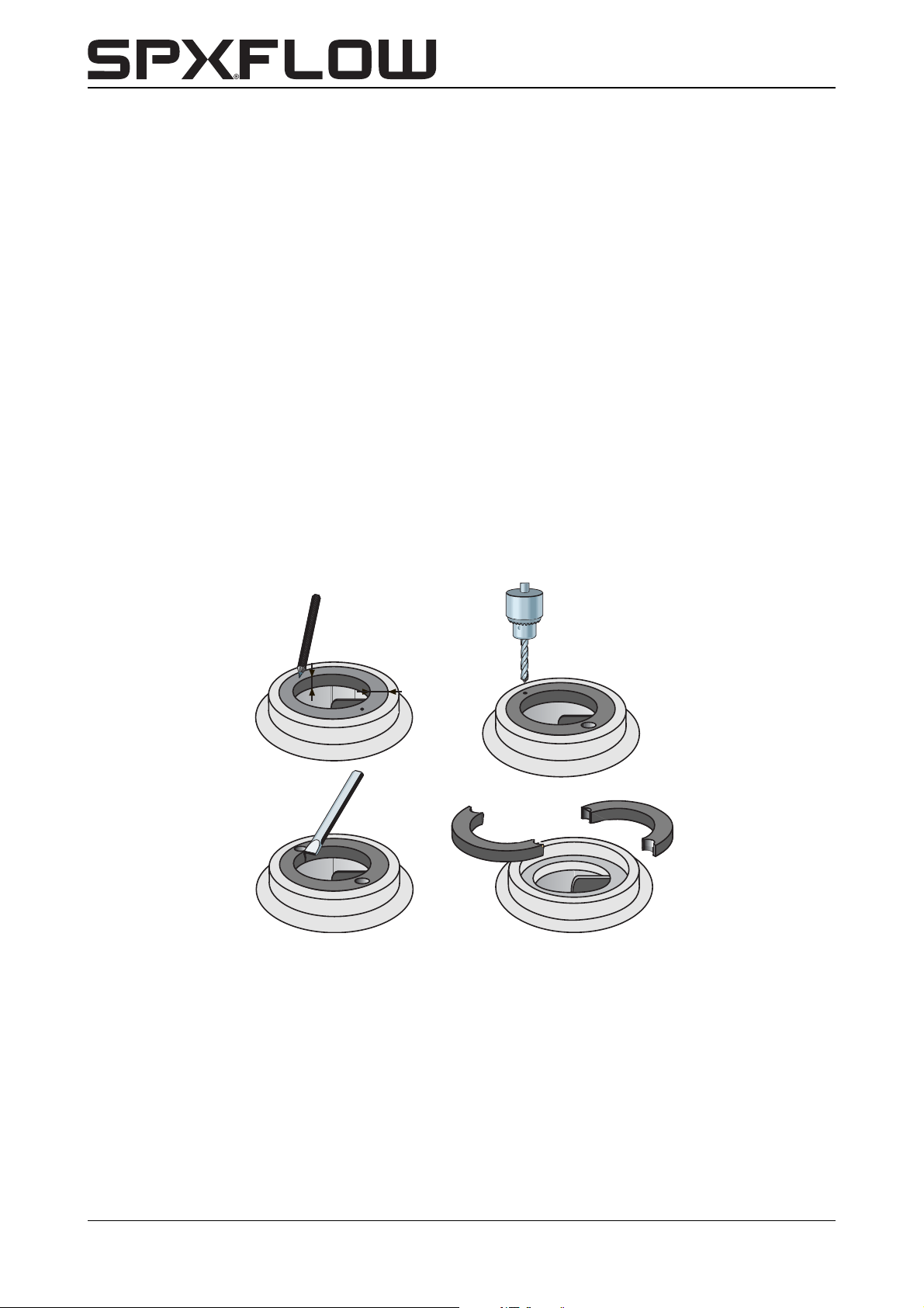
Figure 4: Removal of wear ring.
1 Measure the thickness (d) and the width (b) of the ring, see figure 4 A.
2 Make a centre hole in the middle of the edge of the ring at two opposite points, see
figure 4 B.
34 Disassembly and assembly CL-CBH/EN (1901) 7.6
3 Use a drill with a diameter just a little bit smaller than the thickness (d) of the ring and
drill two holes in the ring, see figure 4 C. Don't drill deeper than the width (b) of the
ring. Take care not to damage the fitting edge of the pump casing.
4 Use a chisel to cut the remaining part of the ring thickness. Now you can remove the
ring in two parts from the pump casing, see figure 4 D.
5 Clean the pump casing and carefully remove all bore dust and metal splinters.
Page 37
CombiLine-CombiBlocHorti
2420
0100
0900
0810
7.4.2 Assembly
1 Clean and degrease the fitting edge of the pump casing where the wear ring is to be
mounted.
2 Degrease the outer edge of the wear ring and put a few drops of Loctite 641 on it.
3 Fit the wear ring in the pump casing. Take care it is not pushed out of
alignment!
7.5 Disassembling the pump
Start at paragraph 7.5.1 "Back Pull Out-unit" and follow all instructions up to and
including the part you want to remove.
The item numbers used refer to the parts lists and drawings of chapter 9 "Parts".
7.5.1 Back Pull Out-unit
For maintenance and repairs usually it is not necessary to remove the whole pump from
the piping. You only have to remove the integrated pump cover/motor-part, the so called
"Back Pull Out-unit".
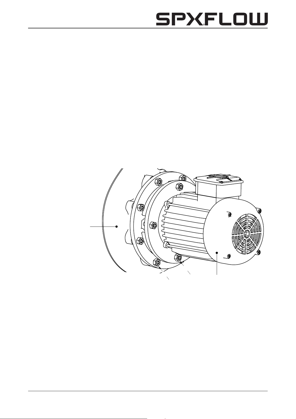
! NEVER start dismantling by loosening the motor fastening nuts (0900). This
may result in irreparable damage to the motor shaft and the mechanical seal!
Figure 5: Location of fastening nuts.
CL-CBH/EN (1901) 7.6 Disassembly and assembly 35
Page 38
1 Loosen the fastening nuts (0810) of the lantern piece, see figure 5.
3
1
2
4
6
8
7
5
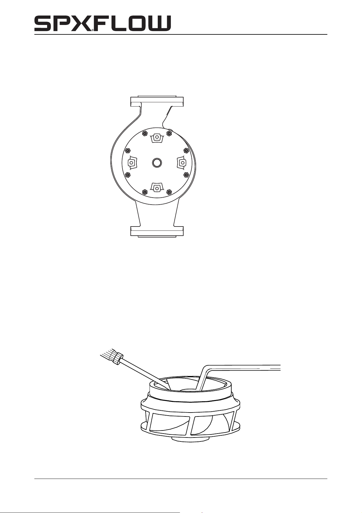
4021
4002
If the pump is still in the piping, start from the bottom side and proceed along the two
sides upward, see figure 6.
2 Pull the Pull-out unit straight out of the pump casing (0100).
Figure 6: Sequence of loosening the lantern piece fastening nuts.
7.5.2 Impeller
➢ If you wish to replace the impeller it is advisable to also replace the mechanical seal and
the bearings.
1 Place the Pull-out unit vertically and let it rest on the electric motor (2420).
2 Block the impeller (0120) against rotating, see figure 7.
3 Loosen the cap nut (1820).
4 Remove the impeller with a pulley puller. The position of the puller’s jaws should as
much as possible coincide with the blades.
5 If provided with shaft sleeve, remove the O-ring (1320) from the impeller hub for
inspection. Do not use a sharp tool!
Figure 7: Loosening the cap nut.
36 Disassembly and assembly CL-CBH/EN (1901) 7.6
Page 39

CombiLine-CombiBlocHorti
7.5.3 Mechanical seal
1 Remove the impeller key (1860) from the shaft end.
2 If present, remove the shaft sleeve (1200) with the rotating part of the mechanical
seal (1220B) from the shaft.
3 Pull the rotating part of the mechanical seal off the shaft or the shaft sleeve.
4 To remove the static part of the mechanical seal first remove the lantern piece, see
paragraph 7.5.4 "Lantern piece". Then remove the static part of the mechanical seal
(1220A) from its seat by pushing at the back through the shaft hole of the lantern
piece.
7.5.4 Lantern piece
1 Loosen the motor fastening screws (0900) and remove the lantern piece (0110) from
the electric motor.
2 Remove the O-ring (0300) for inspection. Do not use a sharp tool!
CL-CBH/EN (1901) 7.6 Disassembly and assembly 37
Page 40
7.6 Disassembling the electric motor
4005
The item numbers used refer to figure 17 on page 59.
7.6.1 Electric motor stator
1 Put the electric motor vertically with the shaft end pointing downward. Let the motor
flange rest on e.g. 2 wooden blocks with an opening in the working surface for the
shaft end.
2 Remove the fan cover (2420-1) by loosening the 4 screws.
3 Remove the cooling fan (2420-2). For electric motors from 2,2 kW you must first
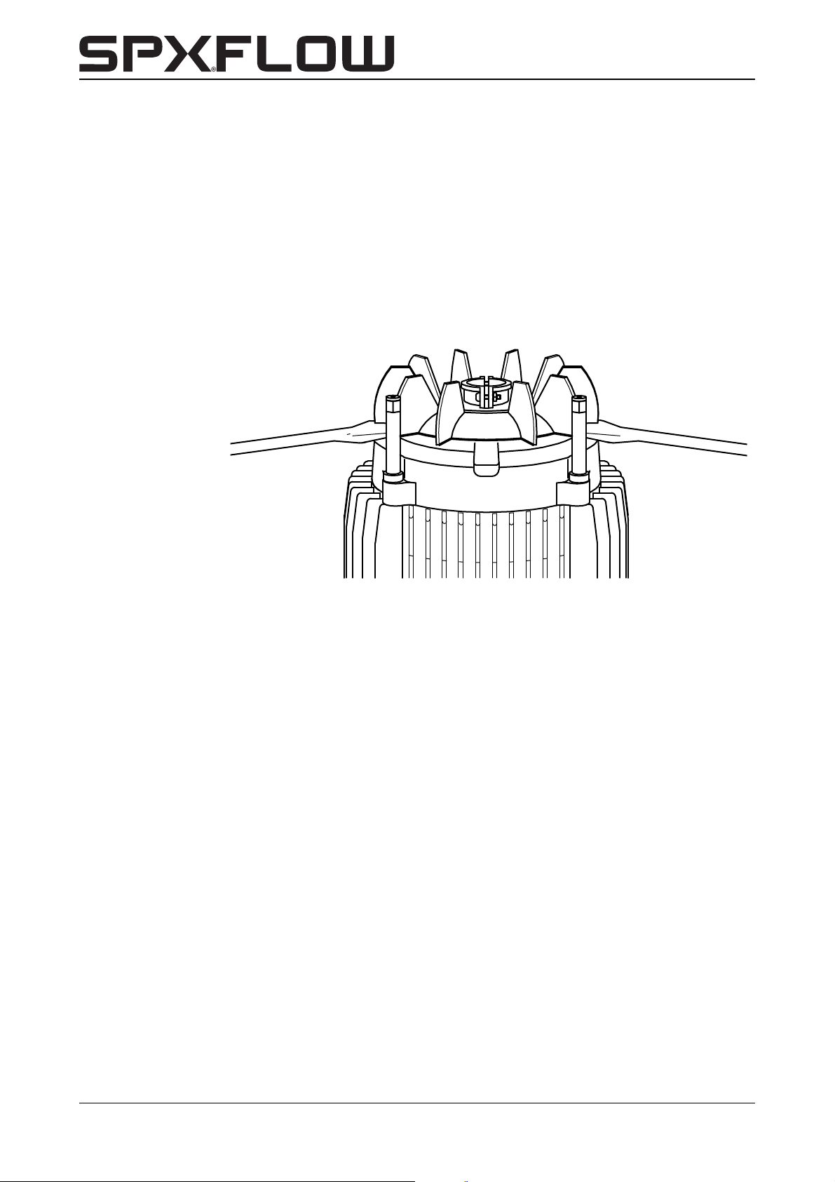
loosen 2 clamping screws. After that, remove the fan from the shaft end by means of
2 broad screw drivers, see figure 8.
Figure 8: Removing the cooling fan.
4 Loosen the 4 tie rods (2420-3).
5 Carefully lift up and remove the rear bearing shield (2420-4) by means of two broad
screwdrivers.
6 Remove the wave spring (2420-5).
7 Carefully lift up the stator (2420-6) by means of 2 broad screw drivers and remove it
in vertical direction.
7.6.2 Electric motor bearings
1 Remove the inner circlip (2420-7).
2 Knock on the shaft end, using a plastic hammer, to loosen the shaft (2420-8) with
bearing from the bearing seat of the front bearing shield (2420-11).
3 Remove both bearings (2420-9) using a proper bearing puller. First remove possible
paint from the shaft.
4 Remove the oil-baffle (2420-10) from the rear and front bearing shield (2420-4) and
(2420-11) respectively.
38 Disassembly and assembly CL-CBH/EN (1901) 7.6
Page 41

CombiLine-CombiBlocHorti
7.7 Assembly
For correct tightening moments see paragraph 10.3 "Tightening torques".
! All parts should be clean and undamaged. Bearings and mechanical seal
should be left in the packing as long as possible.
7.8 Assembling the electric motor
The item numbers used refer to figure 17 on page 59.
7.8.1 Electric motor bearings
1 Place the shaft (2420-8) end up on the work table, the key way side up.
2 Place the inner circlip (2420-7) loosely around the shaft.
3 Mount the bearing (2420-9A) onto the shaft.
! If possible heat the bearings on a heating plate up to 90 °C.
Make sure the bearings are mounted straight.
Never hit directly on a bearing: use a mounting bush against the inner bearing
race.
4 Turn the shaft and mount the other bearing (2420-9B).
5 Place the oil-baffle (2420-10) in the seat of the front bearing shield (2420-11).
6 Support the motor flange and mount the shaft with the bearing at the key way side in
the front bearing shield.
! Make sure the bearing is placed straight inside the seating. Knock on the
shaft end with a plastic hammer. Rotate the shaft slightly after every blow.
7 Mount the inner circlip (2420-7). Make sure it is fitted inside the groove in the bearing
seat.
7.8.2 Electric motor stator
1 Carefully slide the stator (2420-6) over the shaft and the rotor (2420-8) and press
the stator into the collar of the front bearing shield. Make sure that the notches in the
cooling fins correspond with the position of the tie rods.
! The terminal box (2420-12) should then be placed at the fan side!
2 Place the wave spring (2420-5) on the rear bearing.
3 Push the rear bearing shield (2420-4) over the bearing (2420-9B). Watch the
position of the holes for the tie rods.
4 Place the oil-baffle (2420-10) in the rear bearing shield.
5 Fix the tie rods (2420-3) and tighten them crosswise and gradually.
6 Mount the cooling fan (2420-2). The smaller types only have a light drive fit. Press the
fan over the shaft end by means of a mounting bush. For the larger types, also tighten
the clamping screws.
7 Mount the fan cover (2420-1).
8 Check whether the shaft end can be rotated.
CL-CBH/EN (1901) 7.6 Disassembly and assembly 39
Page 42

7.9 Assembling the pump
The item numbers used refer to the parts lists and drawings of chapter 9 "Parts".
7.9.1 Mechanical seal
! A mechanical seal is a vulnerable precision part. Leave the mechanical seal
inside its original packaging until you mount it. Make sure the work site is free
from dust and that the parts and tools are clean. Remove possible paint on
parts. Never put the sliding rings down on the sliding surfaces.
1 If applicable screw the studs (0950) into the lantern piece (0110).
2 Grease the seat of the static ring of the mechanical seal with Molycote 111.
3 Place the lantern piece (0110) flat on the work surface and press the static ring
(1220-A) of the mechanical seal inside. If necessary use a plastic pressure piece.
! DO NOT hammer the ring inside!
4 Fit the lantern piece to the electric motor and proceed with mounting the mechanical
seal.
! Be careful not to damage the centring rim of the motor flange.
If the pump is not fixed straight to the lantern piece the bearings and
mechanical seal will be damaged.
5 For pumps provided with a shaft sleeve: Grease the shaft with Molycote 111 and
mount the shaft sleeve (1200) onto the shaft end.
6 Put some soap suds on the bellows and slide the rotating part of the mechanical seal
(1220-B) onto the shaft sleeve or the shaft, until the seal faces of the two seal
components just touch each other.
! At that moment, stop pushing the bellows against the spring tension! After the
impeller has been mounted, the mechanical seal will be at the right pre-load.
7.9.2 Impeller
1 Place the key (1860) in the key way of the shaft.
2 For pumps provided with shaft sleeve and for CL 4/4 and CL 5/4: Grease the
impeller hub and the O-ring seat with Molycote 111 and mount the O-ring (1320).
3 Mount the impeller (0120) onto the shaft. The impeller will compress the bellows of
the mechanical seal, giving it the correct pre-load.
4 Put a drop of Loctite 243 on the thread of the cap nut (1820) and fit it onto the shaft.
CL 4/4 and CL 5/4: First place the washer (1825).
! Apply the Loctite only on the thread of the cap nut and not on other parts! It
might run in between the shaft and the impeller hub and in that case the
impeller will get stuck on the shaft!
40 Disassembly and assembly CL-CBH/EN (1901) 7.6
Page 43
CombiLine-CombiBlocHorti
0100
0800
7.9.3 Pull-out unit
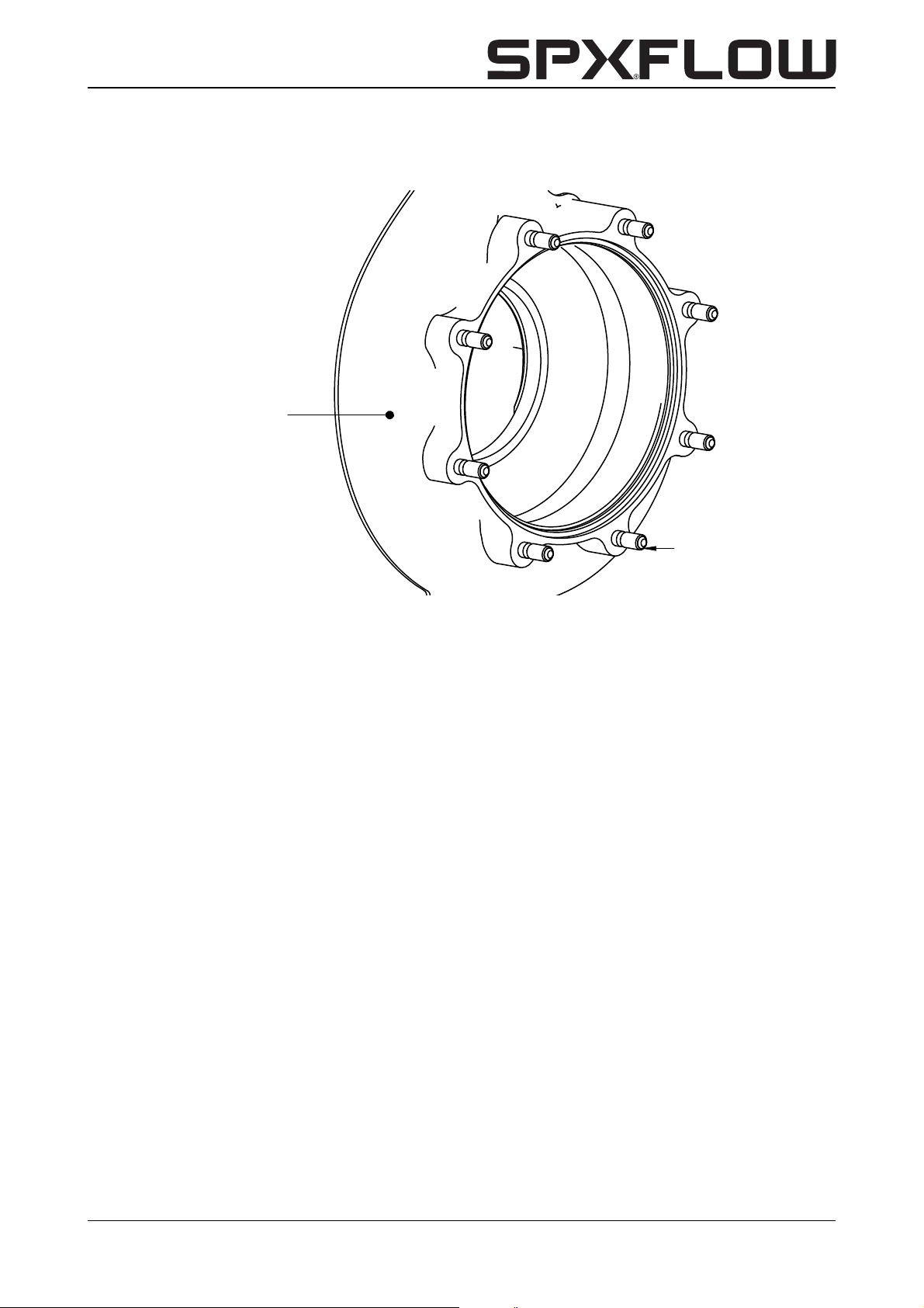
1 If the studs (0800) were dismantled, screw them into the pump casing (0100).
Figure 9: Pump casing with studs.
2 Grease the outer rim of the impeller entry with Molycote 107.
3 Grease the sealing collar of the lantern piece with Molycote 111 and place the O-ring
(0300) in the groove.
4 Mount the Back Pull Out-unit into the pump casing and tighten the fastening nuts
(0810) crosswise.
5 Check whether the shaft end can be rotated, using a screwdriver in the hole of the fan
cover.
CL-CBH/EN (1901) 7.6 Disassembly and assembly 41
Page 44

42 Disassembly and assembly CL-CBH/EN (1901) 7.6
Page 45
CombiLine-CombiBlocHorti
A
A
31.5
296
180
95
6962
8 Dimensions and weights
8.1 Weight
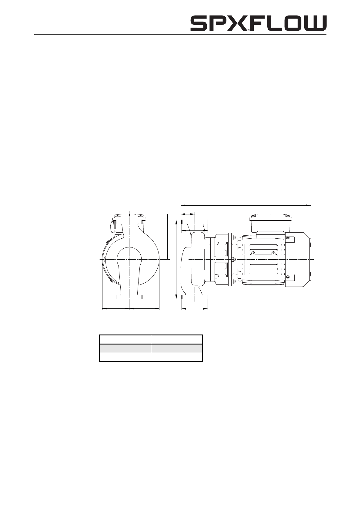
The weight of the pump is indicated on the label on the cover of this manual and on a
similar label on the packaging.
8.2 Dimensions CombiLine 4/4 and 5/4
Figure 10: Dimensions drawing CombiLine 4/4 and 5/4.
Pump type A
4/4 G 1 1/2
5/4 G 2
CL-CBH/EN (1901) 7.6 Dimensions and weights 43
Page 46
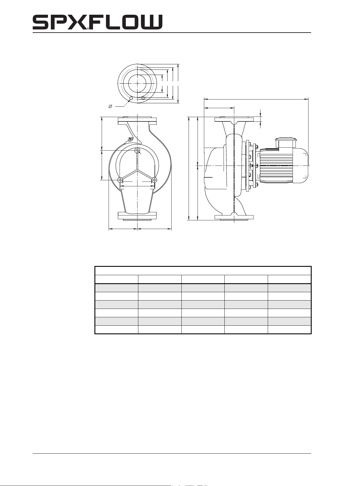
8.3 Dimensions CombiLine ND6
G
F
CD
B
H
ML
J2 J1
K
O
N
P
R
S x T
W
Figure 11: Dimensions drawing CombiLine ND6.
Table 4: Flange dimensions CombiLine ND6.
EN1092-2 (DIN2531) PN6 and ISO7005
NOPRS x T
32 78 90 140 4 x 14
40 80 100 130 4 x 14
50 90 110 140 4 x 14
65 110 130 160 4 x 14
80 128 150 190 4 x 18
100 148 170 210 4 x 18
44 Dimensions and weights CL-CBH/EN (1901) 7.6
Page 47
CombiLine-CombiBlocHorti
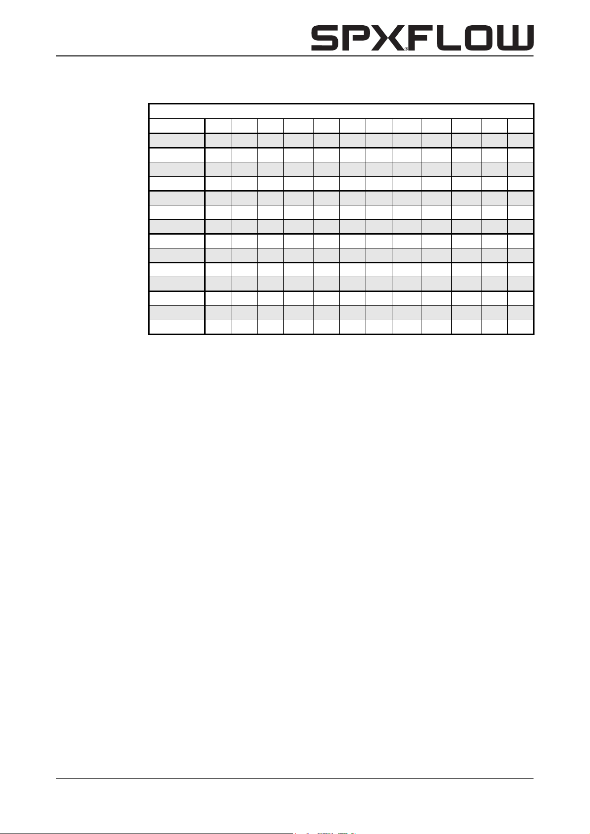
ND6 acc. to EN1092-2 (DIN2531) PN6 and ISO7005
CL B C D F H J1 J2 K L M N W
32-125 250 125 125 74 19 96 85 70 79 80 32 M16
40C-125 250 125 125 79 18 96 85 92 85 75,5 40 M16
40-160 320 160 160 77 18 115 115 91 72,5 118,5 40 M16
40-200 360 180 180 76,5 18 141 141 93,5 105 124 40 M16
50-125 280 140 140 86 18 108 89 105 76,5 99 50 M16
50-160 340 170 170 87,5 18,5 120 115 107,5 85 127,5 50 M16
50-200 380 190 190 85,5 18,5 141 141 107 108,5 138,5 50 M16
65-125 340 170 170 115 18 120 100 127,5 101 121 65 M16
65-160 340 170 170 106,5 18 135 115 124 88,5 128,5 65 M16
80-125 360 180 180 130 20 143 109 143 124 118,5 80 M16
80-160 400 200 200 131 20,5 147 123 146,5 127 136,5 80 M16
100-150 560 280 280 148 18 194 145 105,5 116 239 100 M16
100-160 560 260 300 187,5 21 189 150 184,5 170 172,5 100 M16
100-200 590 280 310 171 27 195 163 195 169 192,5 100 M16
CL-CBH/EN (1901) 7.6 Dimensions and weights 45
Page 48
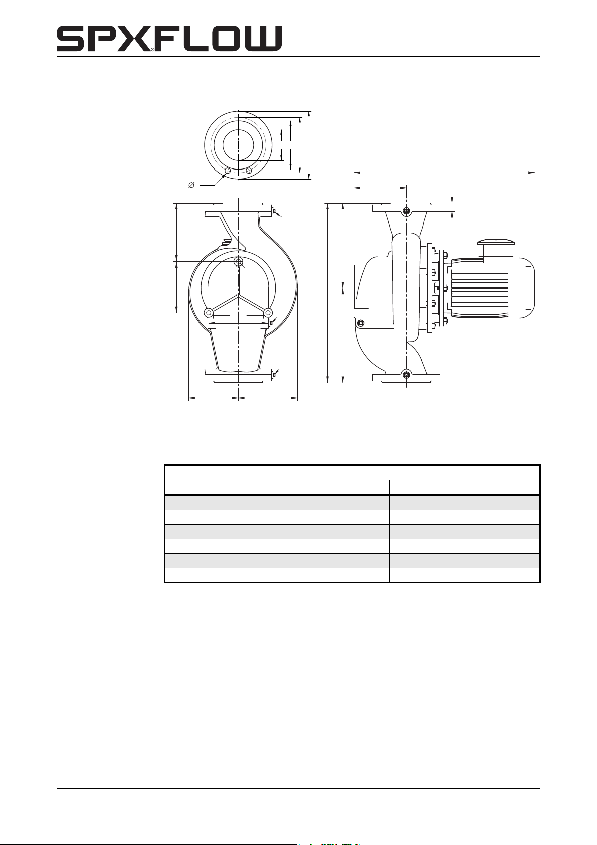
8.4 Dimensions CombiLine ND10
W
G
F
CD
B
H
ML
J2 J1
K
O
N
P
R
S x T
X1
X2
X3
Figure 12: Dimensions drawing CombiLine ND10.
Table 5: Flange dimensions CombiLine ND10.
EN1092-2 (DIN2532) PN10 and ISO7005
NOPRS x T
65 122 145 185 4 x 18
80 138 160 200 8 x 18
100 158 180 220 8 x 18
125 188 210 250 8 x 18
150 212 240 285 8 x 18
200 268 295 340 8 x 22
46 Dimensions and weights CL-CBH/EN (1901) 7.6
Page 49
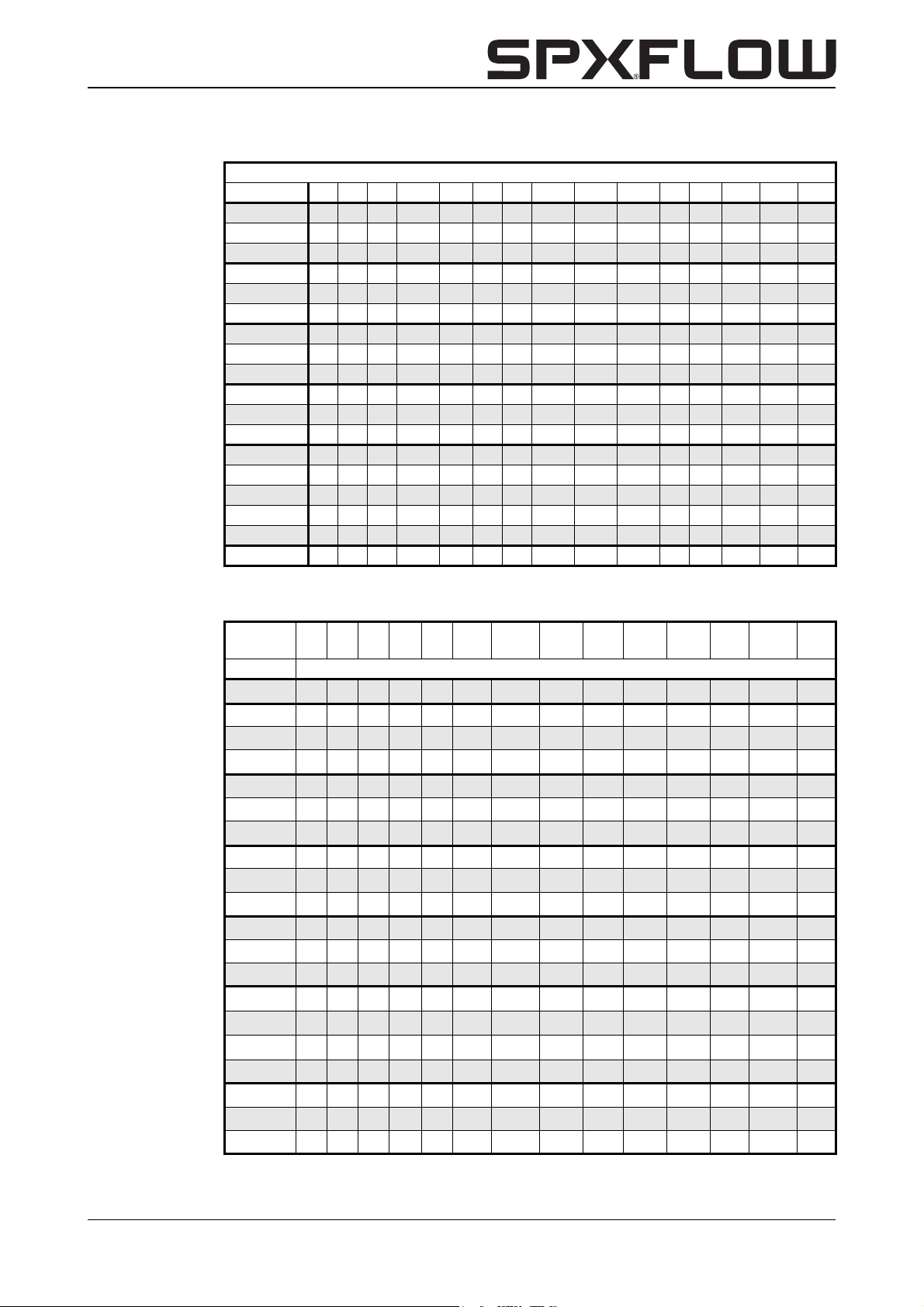
CombiLine-CombiBlocHorti
ND10 acc. to EN1092-2 (DIN2532) PN10 and ISO7005
CL B C D F H J1 J2 K L M N W X1 X2 X3
65-125 340 170 170 115 22 120 100 127,5 101 121 65 M16 G3/8 G3/8 G1/8
65-160 340 170 170 106,5 22 135 115 124 88,5 128,5 65 M16 G3/8 G3/8 G1/8
65-200* 440 220 220 132,5 21 151 141 133,5 102,5 169,5 65 M16 G3/8 G3/8 G3/8
80-125 360 180 180 130 24 143 109 143 124 118,5 80 M16 G3/8 G3/8 G3/8
80-160 400 200 200 131 24,5 147 123 146,5 127 136,5 80 M16 G3/8 G3/8 G3/8
80-200* 530 265 265 113 22 170 143 151 139 192 80 M16 G3/8 G3/8 G3/8
100-160 560 260 300 187,5 27 189 150 184,5 170 172,5 100 M16 G3/8 G3/8 G3/8
100-200 590 280 310 171 27 195 163 195 169 192,5 100 M16 G3/8 G3/8 G3/8
80A-250 590 280 310 214,5 27 200 176 195 169 175 100 M16 G3/8 G3/8 G3/8
125-160* 750 375 375 247 26 223 178 225 195 280 125 M16 G3/8 G3/8 G3/8
125C-200 750 375 375 247 26 223 178 225 195 280 125 M16 G3/8 G3/8 G3/8
100A-250 730 355 375 224,5 28,5 237 202 225 195 241 125 M16 G3/8 G3/8 G3/8
150-125 850 400 450 287 28,5 294 218 320 257,5 255 150 M16 G3/8 G3/8 G3/8
150-160 750 315 435 287 28,5 257 200 310 230 175 150 M16 G3/8 G3/8 G3/8
150-200 720 315 405 245 24,5 245 198 258 198,5 214 150 M20 G3/8 G3/8 G3/8
125A-250 805 355 450 282,5 28,5 261 216 310 254 212 150 M16 G3/8 G3/8 G3/8
150-250 850 400 450 283 28,5 279 227 320 257,5 255 150 M20 G3/8 G3/8 G3/8
200-200 900 400 500 337 26,5 297 237 298 230,5 280 200 M20 G3/8 G3/8 G3/8
* Cam on flange rotated by 90 degrees.
Motor
4 poles
CL G
32-125 369
40C-125 374 402
40-160 399 415
40-200 415 450
50-125 419
50-160 413 429
50-200 427 462 462
65-125 440 456
65-160 448 483
65-200 499 499 538
80-125 476 511
80-160 522 522 561
80-200 483 522 537
100-150 493 528 528
100-160 570 609 624
100-200 586 601 608 679 719
80A-250 656 728 768 927 905 875
125-160 670 685 692 763 803
125C-200 692 763 803 962
100A-250 742 782 941 919 889 988
63 71 80 90S 90L 100L
100L
1)
112M 132S 132M 160M 160L
160L
2)
180L
CL-CBH/EN (1901) 7.6 Dimensions and weights 47
Page 50
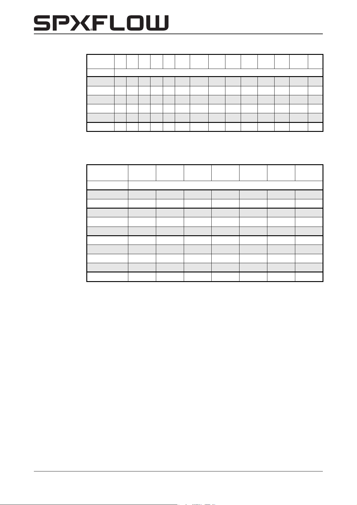
Motor
4 poles
CL G
150-125 717 732 739
150-160 728 799 839 998
150-200 699 770 810 969 947
125A-250 840 999 977 947 1046
150-250 1006 984 954 1053
200-200 906 1065 1043 1013 1112
1)
2)
63 71 80 90S 90L 100L
3 kW
18,5 kW
100L
1)
112M 132S 132M 160M 160L
160L
2)
180L
Motor
6 poles
112M 132S
132S
1)
132M 160M
160M
2)
160L
CL G
100-200 630 685 645
80A-250 678 733 693 768 927
125-160 714 769
125C-200 714 769 729 803
100A-250 692 747 707 782 941 842
150-160 750 805 765 839
150-200 721 776 736 810 969
125A-250 805 765 840 999 900
150-250 772 847 1006 907 984
200-200 831 906 1065 966
1)
3 kW
2)
5,5 kW
48 Dimensions and weights CL-CBH/EN (1901) 7.6
Page 51
CombiLine-CombiBlocHorti
aa
ac
ae
ag
ai x
∅
ak
vb
vc
vj
ve
va
vd
vf
db zh
am
zb
an
ab
ad
af
ah
aj x al
tuta
∅
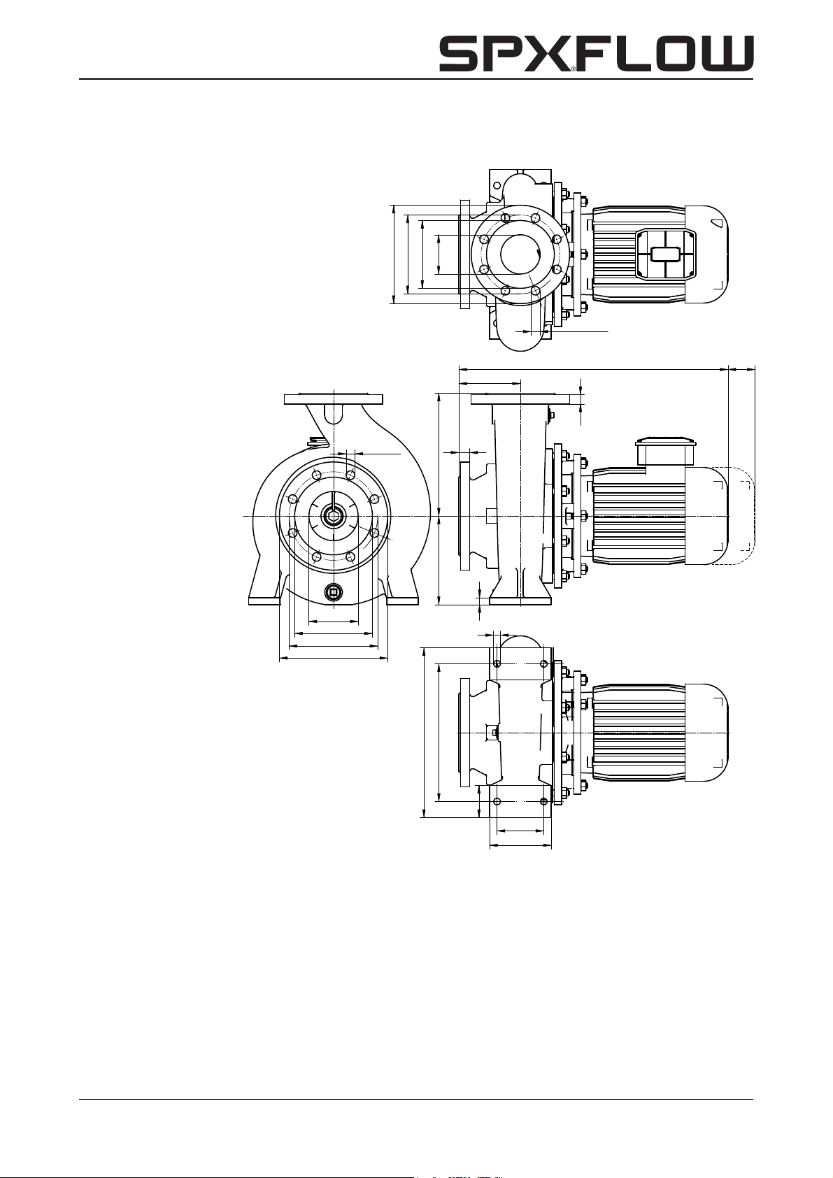
8.5 Dimensions CombiBlocHorti
Figure 13: Pump dimensions CombiBlocHorti.
CL-CBH/EN (1901) 7.6 Dimensions and weights 49
Page 52
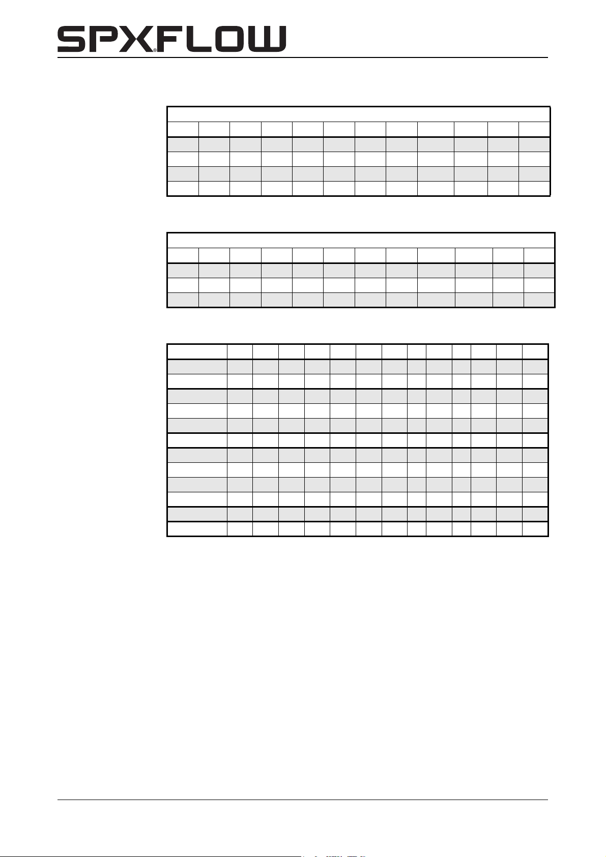
ISO 7005 PN16
aa ab ac ad ae af ag ah ai x ak aj x al am an
100 80 158 138 180 160 220 200 8 x 18 8 x 18 22 22
125 100 188 158 210 180 250 220 8 x 18 8 x 18 24 22
150 125 212 188 240 210 285 250 8 x 23 8 x 18 24 24
150 150 212 212 240 240 285 285 8 x 23 8 x 23 24 24
ISO 7005 ≅ EN 1092-2
ISO 7005 PN10
aa ab ac ad ae af ag ah ai x ak aj x al am an
200 150 268 212 295 240 340 285 8 x 23 8 x 23 26 24
200 200 268 268 295 295 340 340 8 x 23 8 x 23 26 26
250 250 320 320 350 350 395 395 12 x 23 12 x 23 28 28
ISO 7005 ≅ EN 1092-2
CBH aa ab db tu va vb vc vd ve vf vj zb zh
80C-200 100 80 180 140 125 280 345 14 95 14 65 125 250
80-250 100 80 200 140 160 315 400 18 120 15 80 125 280
100-160 125 100 200 100 160 280 360 18 120 15 80 125 315
100C-200 125 100 200 140 160 280 360 18 120 15 80 125 280
100C-250 125 100 225 140 160 315 400 18 120 16 80 140 280
125-250 150 125 250 140 160 315 400 18 120 18 80 140 355
150-125 150 150 280 140 160 315 400 18 120 18 80 160 400
150-160 150 150 250 100 160 315 400 18 120 18 80 160 315
150-200 150 150 250 140 160 315 400 18 120 18 80 160 315
150-250 200 150 280 140 200 400 500 23 150 20 100 160 400
200-200 200 200 280 100 200 400 500 23 150 22 100 200 400
250-200 250 250 315 140 200 450 550 23 150 22 100 200 450
50 Dimensions and weights CL-CBH/EN (1901) 7.6
Page 53
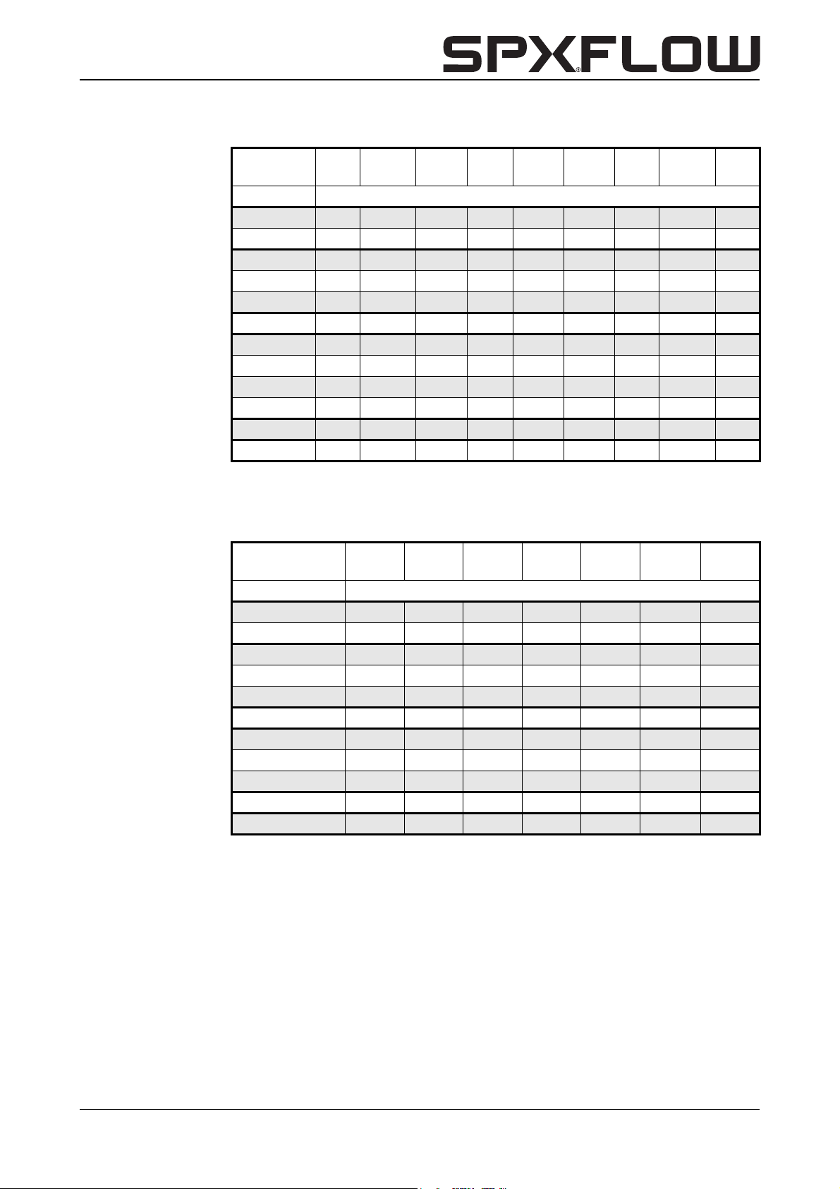
CombiLine-CombiBlocHorti
Motor
4 poles
100L
100L
1)
112M 132S 132M 160M 160L
160L
2)
180L
CBH ta
80C-200 540 555 562 633 673
80-250 554 561 633 673 832 810
100-160 540 555 562 633 673
100C-200 562 633 673 832
100C-250 648 688 847 825 795 894
125-250 688 847 825 795 894
150-125 565 580 587
150-160 597 668 708 867
150-200 597 668 708 867 845
150-250 867 845 815 914
200-200 748 907 885 855 954
250-200 907 885 855 954
1)
3 kW
2)
18,5 kW
Motor
6 poles
112M 132S
132S
1)
132M 160M
160M
2)
160L
CBH ta
80C-200 584 639 599
80-250 583 638 598 673
100-160 584 639
100C-200 584 639 599 673
100C-250 598 653 613 688 847 748
125-250 653 613 688 847 748
150-160 609 664 624
150-200 619 674 634 708
150-250 633 708 867 768 845
200-200 633 708 867 768
250-200 907 808 885
1)
3 kW
2)
5,5 kW
CL-CBH/EN (1901) 7.6 Dimensions and weights 51
Page 54

52 Dimensions and weights CL-CBH/EN (1901) 7.6
Page 55

CombiLine-CombiBlocHorti
9Parts
9.1 Ordering parts
When ordering parts always quote the following data:
1Your address.
2 The quantity, item number and the description of the part.
3 The pump number. The pump number is stated on the label on the cover of this
manual and on the name plate of the pump.
4 In the event of different electric motor voltage you should state the correct voltage.
9.2 Recommended spare parts
Parts marked with a * are recommended spare parts.
CL-CBH/EN (1901) 7.6 Parts 53
Page 56
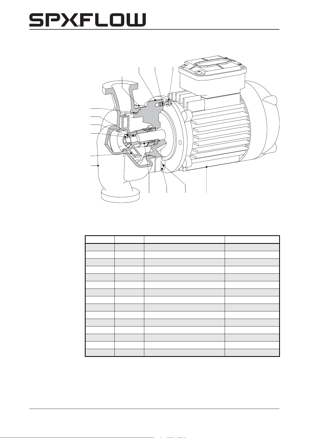
9.3 CombiLine with thread connections
0900
0950
0110
1820
1860
0300
0100
1220
0800
0810
2420
0120
1825
2400
2405
Figure 14: Sectional drawing of CL 4/4-5/4.
See figure 14.
Item Quantity Description Material
0100 1 pump casing cast iron
0110 1 lantern piece cast iron
0120* 1 impeller cast iron
0300* 1 O-ring EPDM
0800 4 stud steel
0810 4 nut steel
0900 4 nut steel
0950 4 stud steel
1220* 1 mechanical seal -1820* 1 nut brons
1825* 1 washer stainless steel
1860* 1 key stainless steel
2400 1 name plate stainless steel
2405 2 rivet stainless steel
2420 1 motor --
54 Parts CL-CBH/EN (1901) 7.6
Page 57
CombiLine-CombiBlocHorti
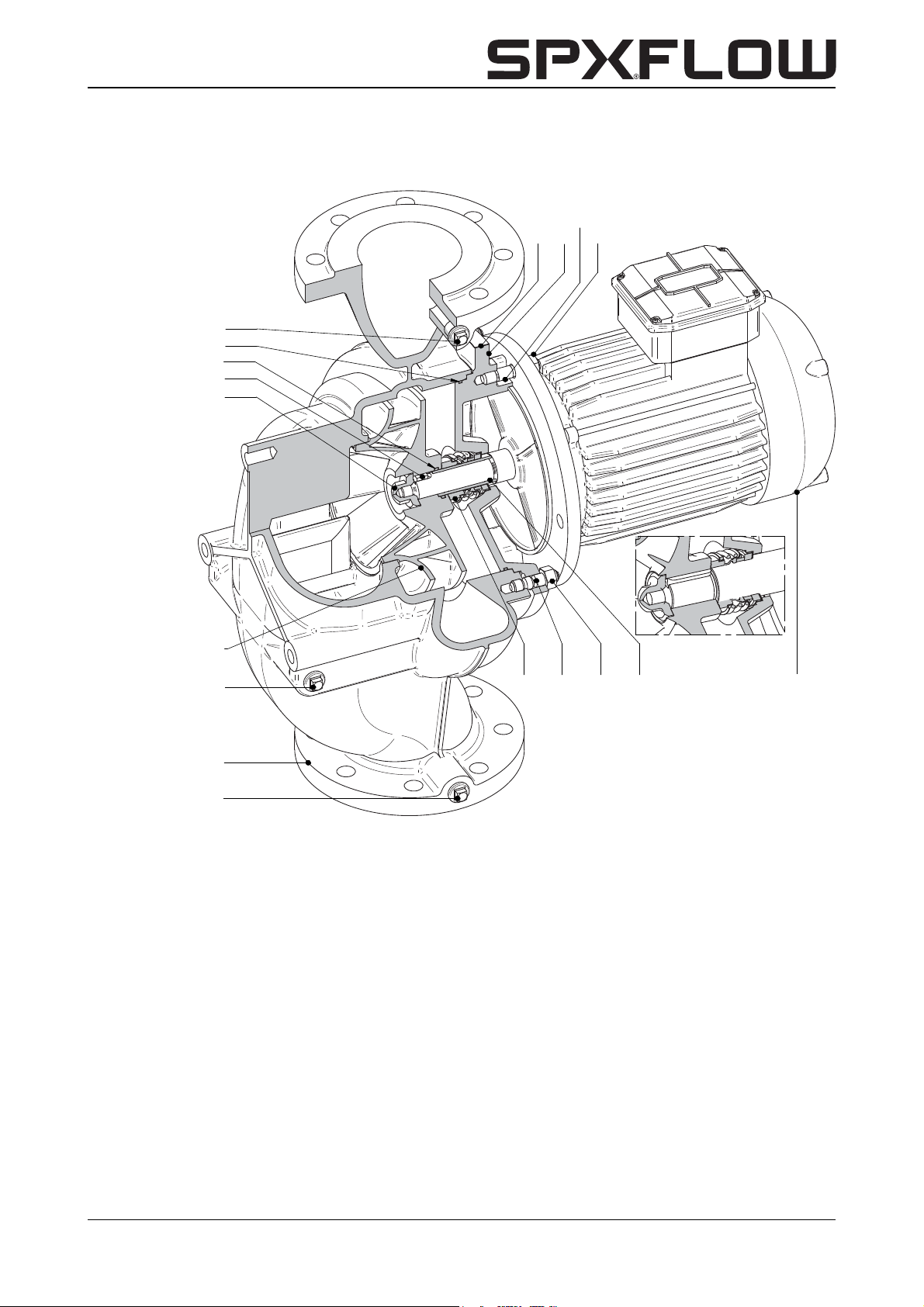
9.4 CombiLine with flange connections
0320
0300
1320
1860
1820
2400
2405
0110
0950
0900
0120
0350
0100
0310
Figure 15: CombiLine.
1220 1200
0800 0810
2420
CL-CBH/EN (1901) 7.6 Parts 55
Page 58
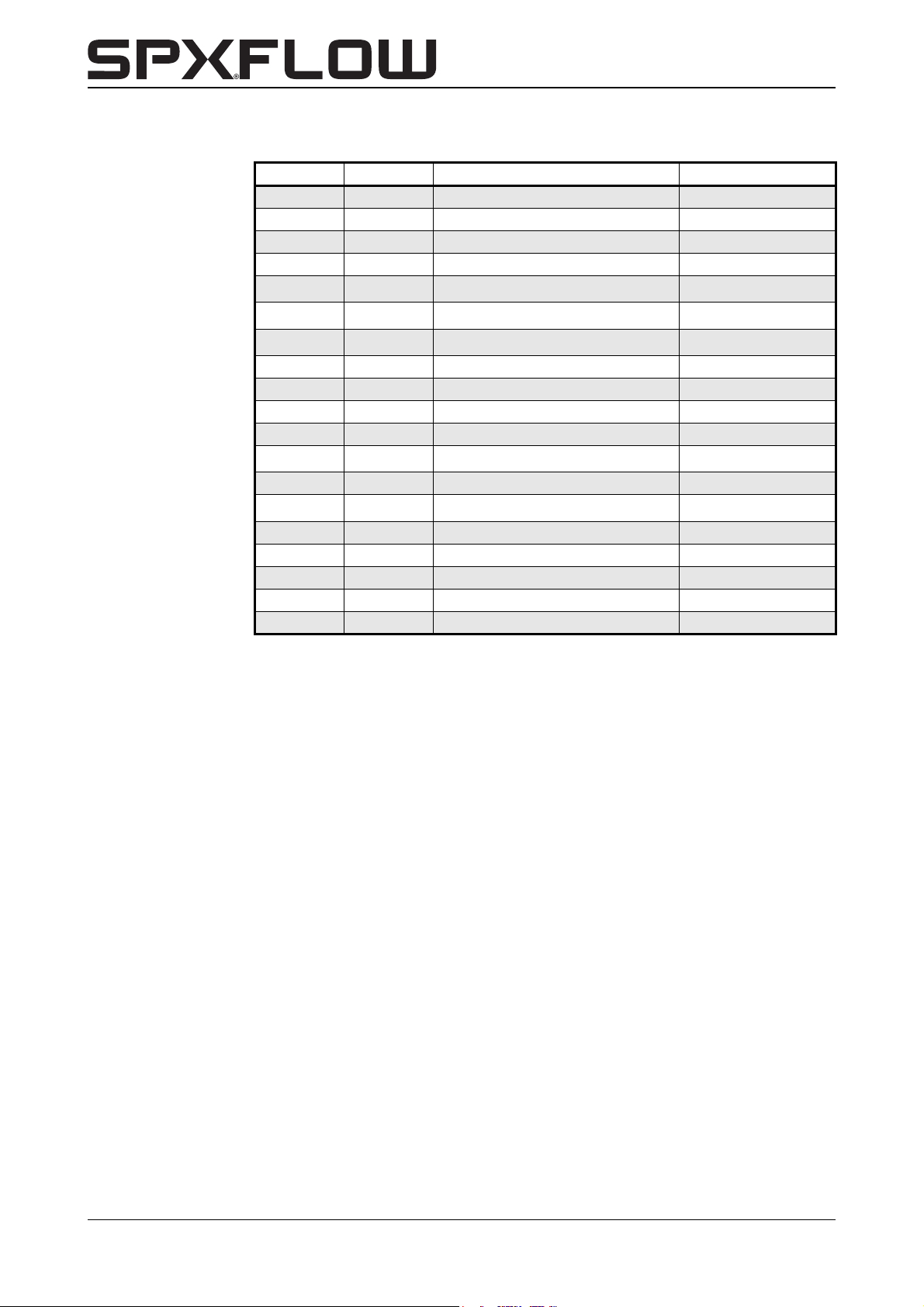
See figure 15.
Item Quantity Description Material
0100 1 pump casing cast iron
0110 1 lantern piece cast iron
0120* 1 impeller cast iron
0300* 1 O-ring EPDM
0310
0320
0350
(1)
(1)
(1)
1 plug steel
1 plug steel
1 plug steel
0800 8 stud steel
0810 8 nut steel
0900 8 nut steel
0950 8 stud steel
1200*
(2)
1 shaft sleeve RG7
1220* 1 mechanical seal --
1320*
(2)
1O-ring EPDM
1820* 1 cap nut stainless steel
1860* 1 key stainless steel
2400 1 name plate stainless steel
2405 2 rivet stainless steel
2420 1 motor --
(1)
only for ND10.
(2)
not applied for IEC132, IEC160 and 6 pole motors.
56 Parts CL-CBH/EN (1901) 7.6
Page 59
CombiLine-CombiBlocHorti
0100
0310
0320
1820
1860
1320
0300
1220
1200
0900
0950
0110
0800
0810
2420
0120
0130
2400
2405
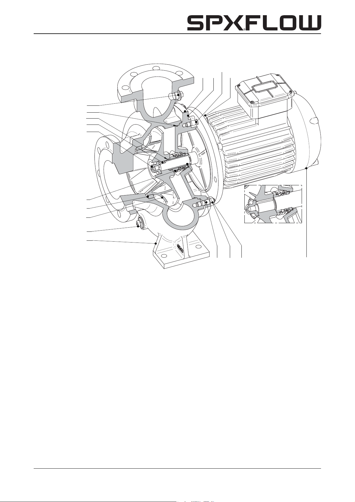
9.5 CombiBlocHorti
Figure 16: CombiBlocHorti.
CL-CBH/EN (1901) 7.6 Parts 57
Page 60
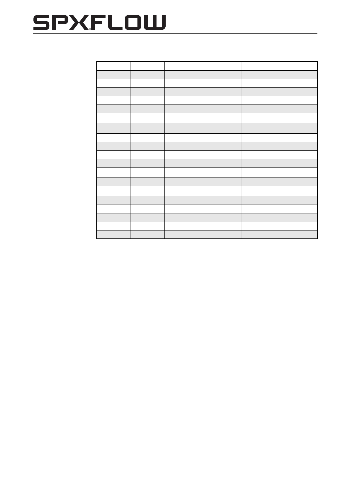
See figure 16
Item Quantity Description Material
0100 1 pump casing cast iron
0110 1 lantern piece cast iron
0120* 1 impeller cast iron
0130* 1 wear ring cast iron
0300* 1 O-ring EPDM
0310
0320
(1)
(1)
1plug steel
1 plug steel
0800 8 stud steel
0810 8 nut steel
0900 8 nut steel
0950 8 stud steel
1200*
(2)
1 shaft sleeve RG7
1220* 1 mechanical seal --
1320*
(2)
1O-ring EPDM
1820* 1 cap nut stainless steel
1860* 1 key stainless steel
2400 1 name plate stainless steel
2405 2 rivet stainless steel
2420 1 motor --
Item 0130 not for pump type 150-125
(1)
only for ND10.
(2)
not applied for IEC132, IEC160 and 6 pole motors.
58 Parts CL-CBH/EN (1901) 7.6
Page 61
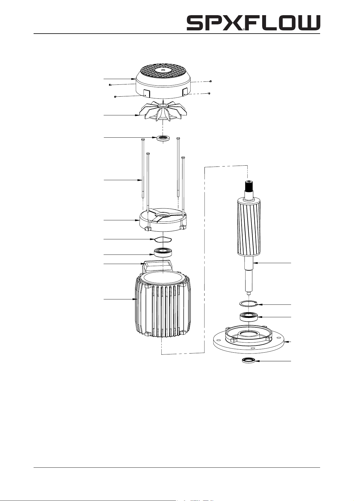
CombiLine-CombiBlocHorti
2420-10
2420-11
2420-9(A)
2420-7
2420-8
2420-6
2420-12
2420-9(B)
2420-5
2420-4
2420-3
2420-10
2420-2
2420-1
4004
9.6 Electric motor
Figure 17: Exploded view of electric motor.
CL-CBH/EN (1901) 7.6 Parts 59
Page 62
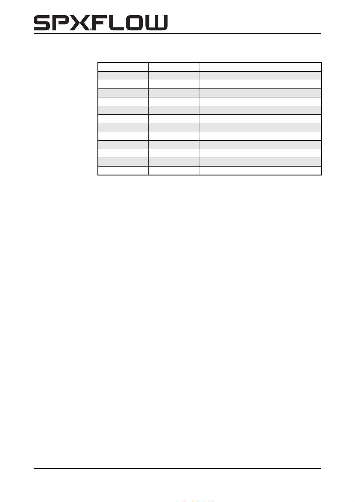
See figure 17.
Item Quantity Description
2420-1* 1 fan cover
2420-2* 1 fan
2420-3* 4 tie rod
2420-4 1 bearing block
2420-5 1 wave spring
2420-6* 1 stator
2420-7 1 inner circlip
2420-8 1 shaft with rotor
2420-9* 2 ball bearing
2420-10* 2 oil seal
2420-11 1 motor flange
2420-12 1 cable junction box
Parts marked with * are available as spare parts.
60 Parts CL-CBH/EN (1901) 7.6
Page 63
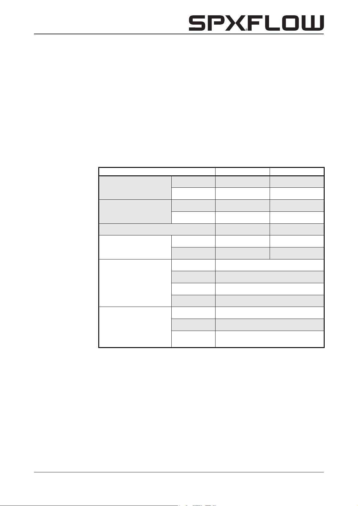
CombiLine-CombiBlocHorti
10 Technical data
10.1 Technical data pumps
Maximum capacity
50Hz
60Hz
CombiLine CombiBlocHorti
400 m3/h 600 m3/h
3
500 m
/h 700 m3/h
Maximum delivery head
Maximum temperature 140 °C 140 °C
Maximum working pressure
Materials
Mechanical seal
50Hz 1 - 28 m 1 - 26 m
60Hz 4 - 40 m 3 - 38 m
ND6 6 bar --
ND10 10 bar 10 bar
pump casing EN-GJL-250 (GG25)
impeller EN-GJL-200 (GG20)
motor shaft X17CrNi 16-2 (1.4057)
shaft sleeve G-CuSn7ZnPb (Rg 7)
type rubber bellows seal
standard EN 12756 (DIN24960)
materials
(carbon/silicon carbide, EPDM bellows)
AQ1EGG
CL-CBH/EN (1901) 7.6 Technical data 61
Page 64
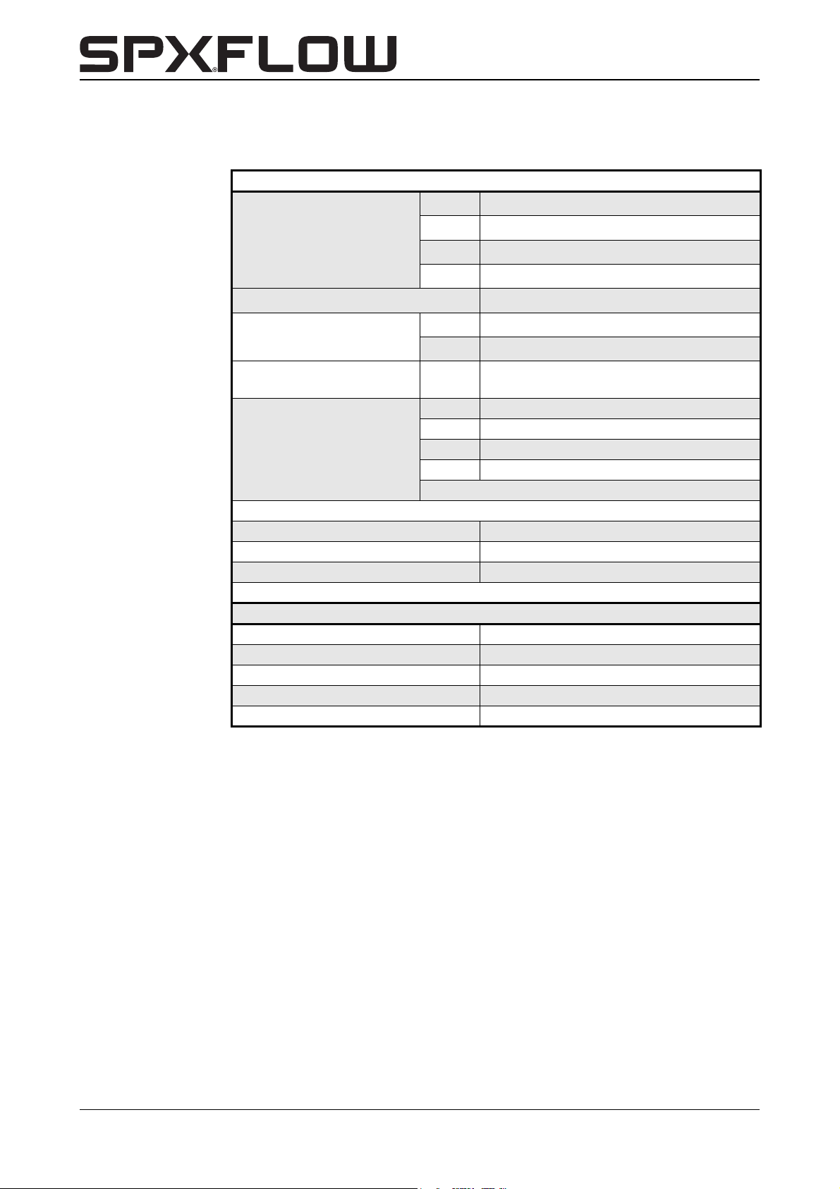
10.2 Technical data electric motor
Type, Frequency, Insulation, Voltage: see name plate on the electric motor.
General
Nominal speed
Speed CL4/4 and CL5/4
2 speed motor with Dahlander
connection
Frequency control, wall
mounted
Voltage
Build B5
Protection class IP 55
Sense of rotation clockwise, looking at fan side
50Hz
50Hz
60Hz
60Hz
1450 min-1 (4 pole)
950 min
-1
(6 pole)
1750 min-1 (4 pole)
-1
1150 min
(6 pole)
1450 min-1/ 2900 min
50Hz
60Hz
1450/950 min
1750/1150 min-1 (4/6 pole)
-1
(4/6 pole)
From 1,1 kW, range 10 to 60 Hz
50Hz 230/400 V (≤ 1,5 kW)
50Hz 400/695 V (≥ 2,2 kW)
60Hz 277/480 V (≤ 1,5 kW)
60Hz 480/830 V (≥ 2,2 kW)
Other voltages/speeds on request
-1
Bearings
Type single row deep groove bearings
Fidelity according to ISO 281
Maximum bearing temperature 90 °C
Bearing at pump side fixed
Bearing at fan side pre-stressed
62 Technical data CL-CBH/EN (1901) 7.6
Page 65
CombiLine-CombiBlocHorti
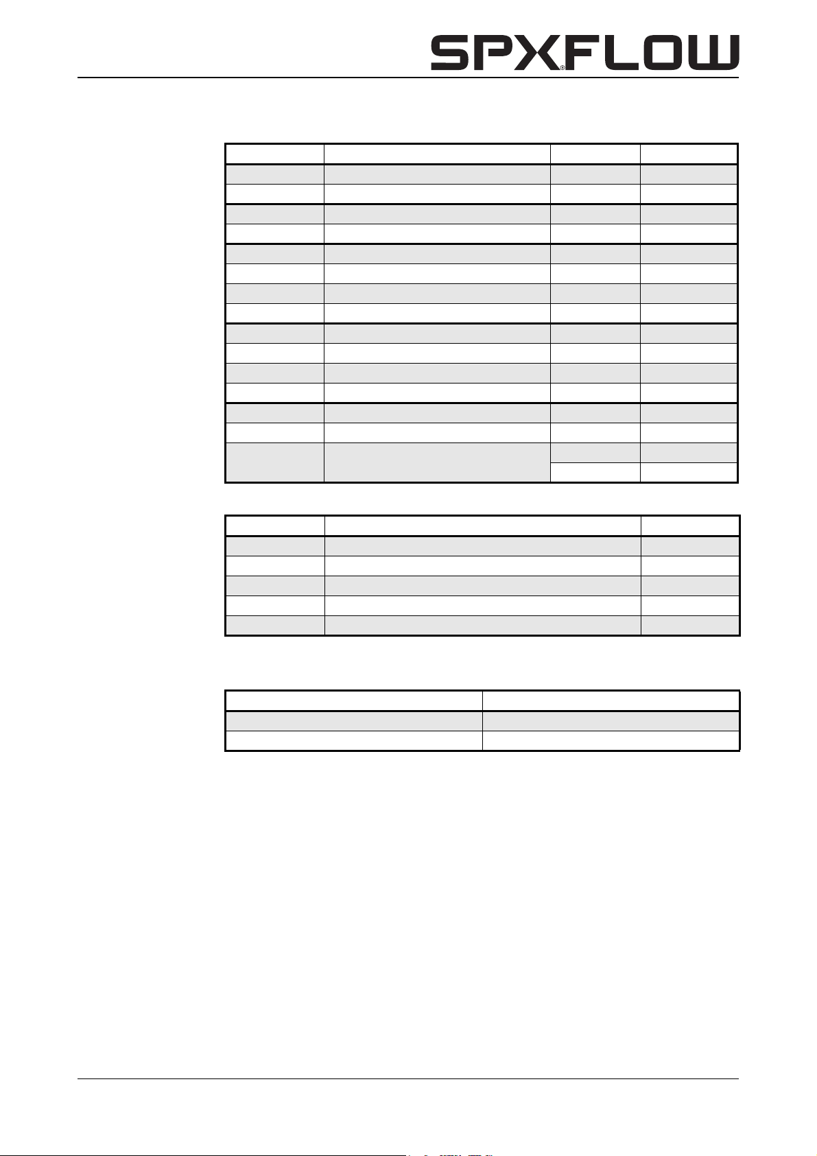
10.3 Tightening torques
Item Description Thread Nm
0800 stud M10 19
0810 nut M10 19
0900 motor fastening nut M8 9,4
0950 stud M8 9,4
1820 cap nut
pump with shaft sleeve all 19
pump without shaft sleeve
M12 32
M12 32
M10 19
M12 32
M16 78
M10 19
M12 32
M16 78
M12 43
M16 105
10.4 Tightening torques CombiLine 4/4 and 5/4
Item Description Nm
0800 stud 12,5
0810 nut 12,5
0900 motor fastening nut 12,5
0950 stud 12,5
1820 cap nut 14
10.5 Recommended liquid locking agents
Table 6: Recommended liquid locking agents.
Description Locking agent
cap nut (1820) Loctite 243
wear ring (0130) Loctite 641
CL-CBH/EN (1901) 7.6 Technical data 63
Page 66
10.6 Noise data
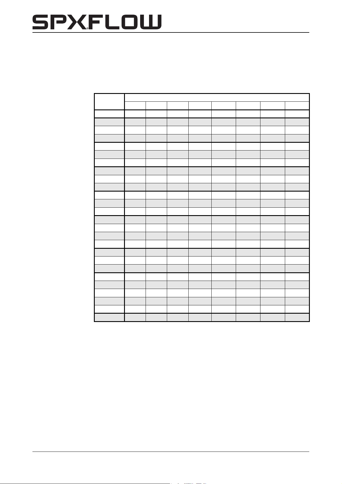
The noise production of a pump depends strongly upon the operating conditions. The
values stated below are for each pump type, equipped with its largest possible motor
power (electric motor: 4-pole, 50 Hz).
Table 7: Noise data.
Type
32-125
40C-125 45
40-160 47
40-200 53
50-125 46
50-160 46
50-200 53
65-125 50
65-160 52
65-200 63
80-125 50
80-160 56
80-200 58
100-150 54
100-160 60
100-200 71
80A-250 76
125-160 70
125C-200 69
100A-250 76
150-125 60
150-160 69
150-200 70
125A-250 76
150-250 76
200-200 76
IEC 63 IEC 71 IEC 80 IEC 90 IEC 100 IEC 112 IEC 132 IEC 160
dB(A) max.
64 Technical data CL-CBH/EN (1901) 7.6
Page 67
CombiLine-CombiBlocHorti
50-125
5
0
-2
0
0
060504
0
302510
1876
51
80
100 150 200 300
4
32
[m]
[m/h]
3
H
1
5
6
7
8
10
15
20
25
30
500
4
3
2
Q
4/4 and 5/4
4/4 and 5/4 2900rpm
32-125
40C-125
40-160
40-200
50-160
65-125
65-160
65-200
80-125
80-160
80A-250
80-200
100-150
100-160
100A-250
125-160
100-200
125C-200
125A-250
150-125
150-160
150-200
200-200
150-250
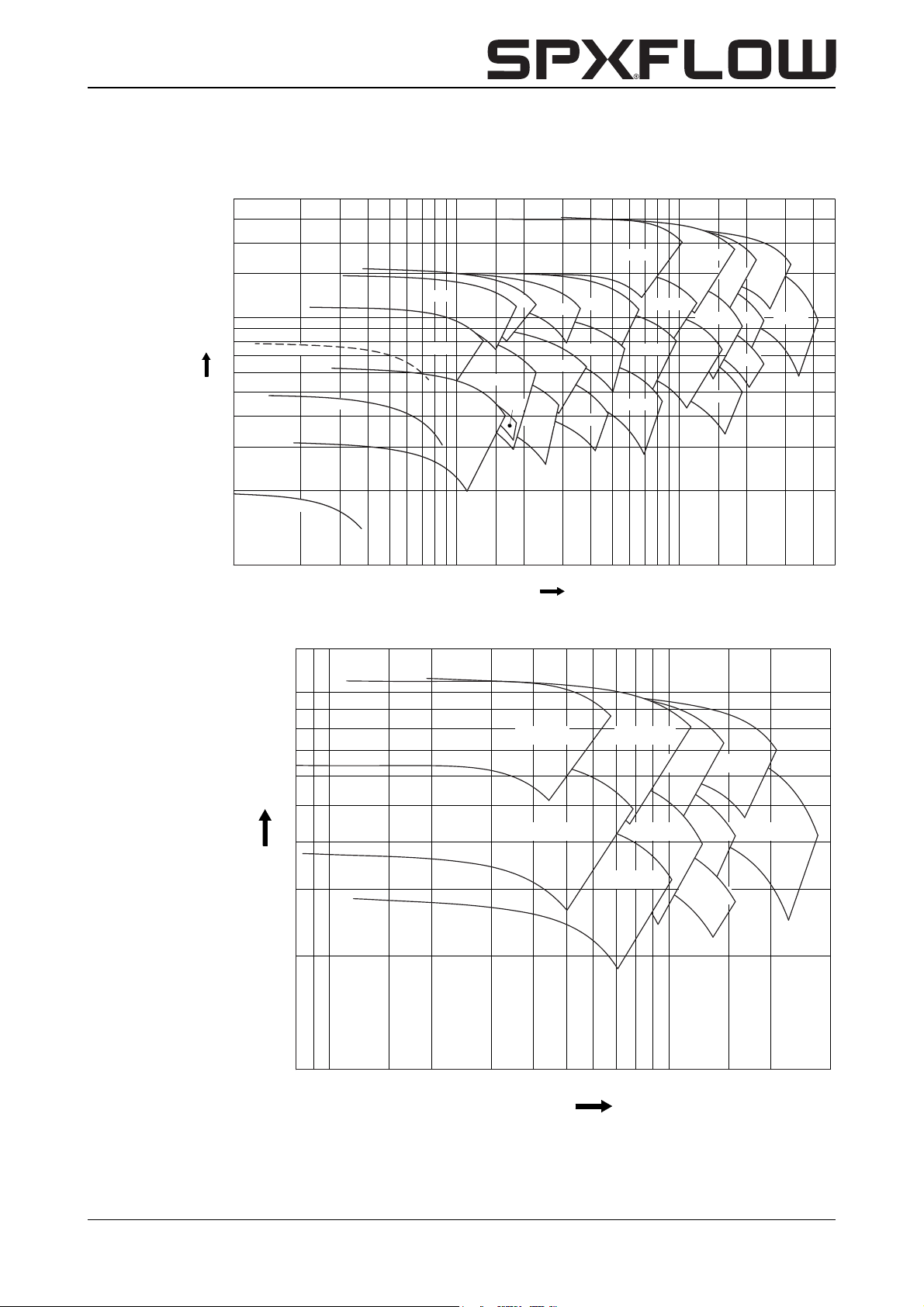
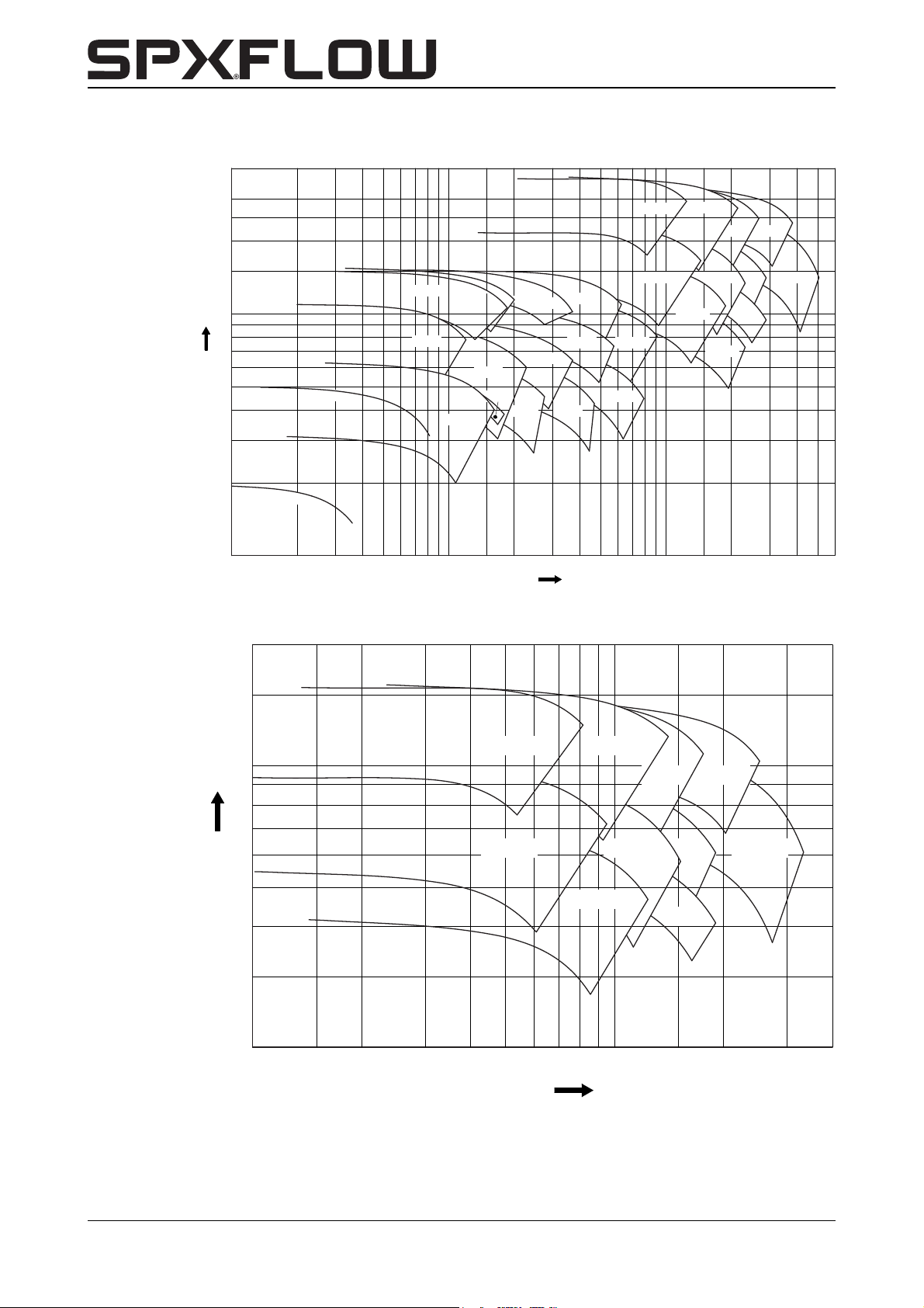
10.7 Hydraulic performance
10.7.1 Performance overviews CombiLine
Figure 18: Performance overview CL 1450 min
[m]
13
10
8
80A-250
7
6
5
4
3
H
2
Figure 19: Performance overview CL 950 min
1
810 15 20 30 405060
100-200
Q
-1
-1
.
.
100A-250
125-160
125A-250
125C-200
150-250
150-200
200-200
150-160
100 150 200 300
80
3
[m/h]
CL-CBH/EN (1901) 7.6 Technical data 65
Page 68
[m/h]
3
Q
2 567810 1520 3040506080100 150 200 300 60043 400
H
1
5
6
7
8
10
15
20
25
30
40
4
3
2
1
[m]
50-125
5
0
-
2
0
0
4/4 and 5/4
32-125
40C-125
40-160
40-200
50-160
65-125
65-160
65-200
80-125
80-160
80A-250
80-200
100-150
100-160
100A-250
125-160
100-200 125C-200
125A-250
150-160
150-200
200-200
150-250
150-125
[m]
[m/h]
3
Q
H
5
6
7
8
10
15
10 15 20 30 40 50 60
80
100 150 200 300 400
4
3
2
20
80A-250
100A-250
125-160
100-200 125C-200
125A-250
150-160
150-200
200-200
150-250
Figure 20: Performance overview CL 1750 min-1.
Figure 21: Performance overview CL 1150 min
66 Technical data CL-CBH/EN (1901) 7.6
-1
.
Page 69
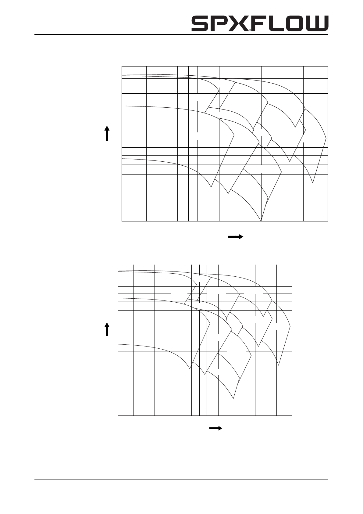
CombiLine-CombiBlocHorti
20 30 40 50 60
80
100 150 200 300 400
[m]
[m/h]
3
H
5
6
7
8
10
15
20
25
30
600
4
3
Q
150-200
100-160
80-250
80C-200
125-250 150-250
150-160
250-200
200-200
150-125
100C-200
100C-250
15 20 30 40 50 60
80
100 150 200 400
[m]
[m/h]
3
H
1
5
6
7
8
10
13
4
3
2
Q
150-200
100-160
80-250
80C-200
125-250 150-250
150-160
250-200
200-200
150-125
100C-200
100C-250
300
10.7.2 Performance overviews CombiBlocHorti
-1
Figure 22: Performance overview CBH 1450 min
Figure 23: Performance overview CBH 950 min
.
-1
.
CL-CBH/EN (1901) 7.6 Technical data 67
Page 70
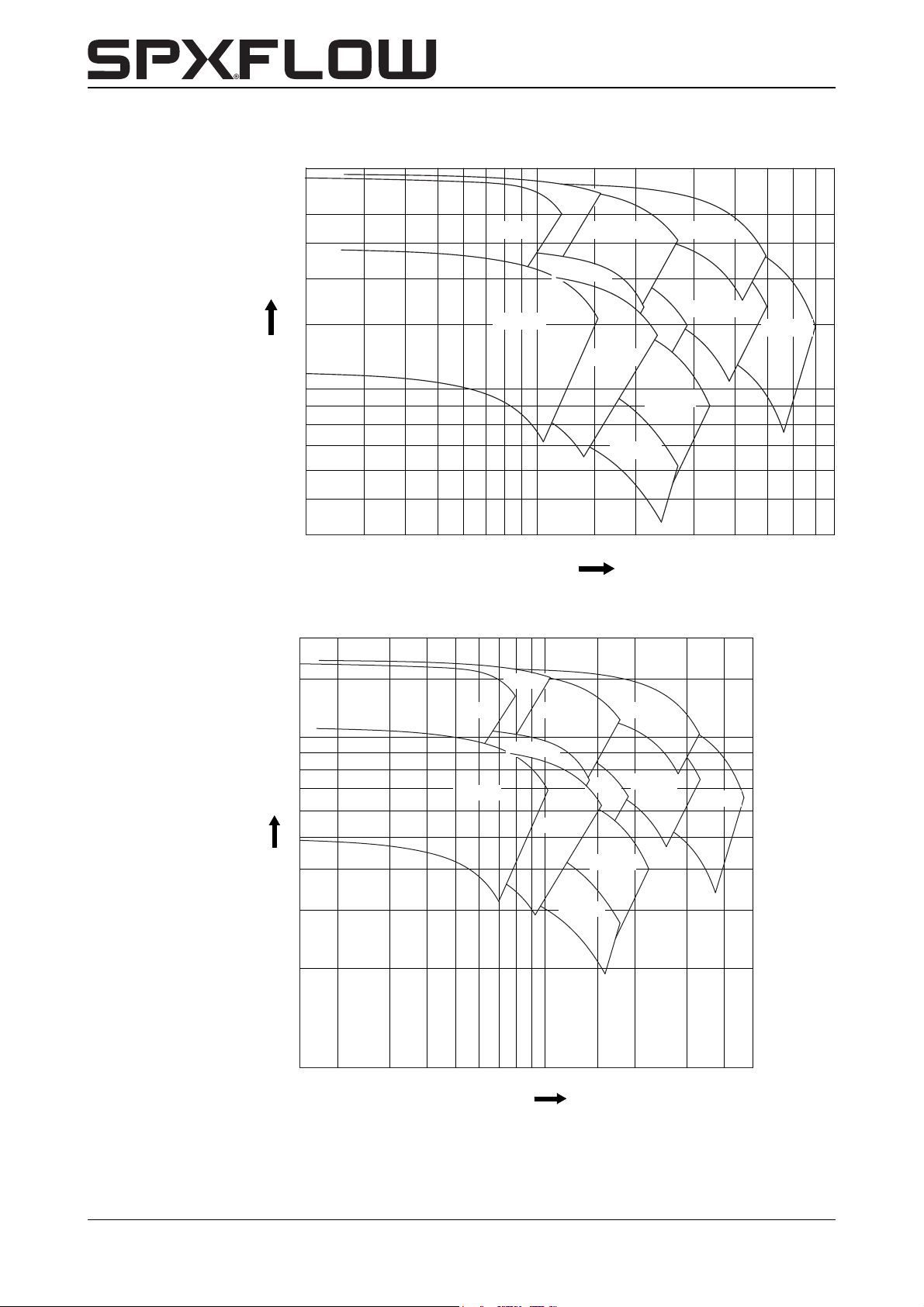
[m]
[m/h]
3
Q
H
5
6
7
8
10
15
20
25
30
40
20 30 40 50 60
80
100 150 200 300 800400 500
4
150-200
100-160
80-250
80C-200
125-250
150-250
150-160
250-200
200-200
150-125
100C-200
100C-250
[m]
[m/h]
3
Q
H
1
5
6
7
8
10
15
15 20 30 40 50 60
80
100 150 200 300 500
4
3
2
20
150-200
100-160
80-250
80C-200
125-250 150-250
150-160
250-200
200-200
150-125
100C-200
100C-250
Figure 24: Performance overview CBH 1750 min-1.
68 Technical data CL-CBH/EN (1901) 7.6
Figure 25: Performance overview CBH 1150 min
-1
.
Page 71
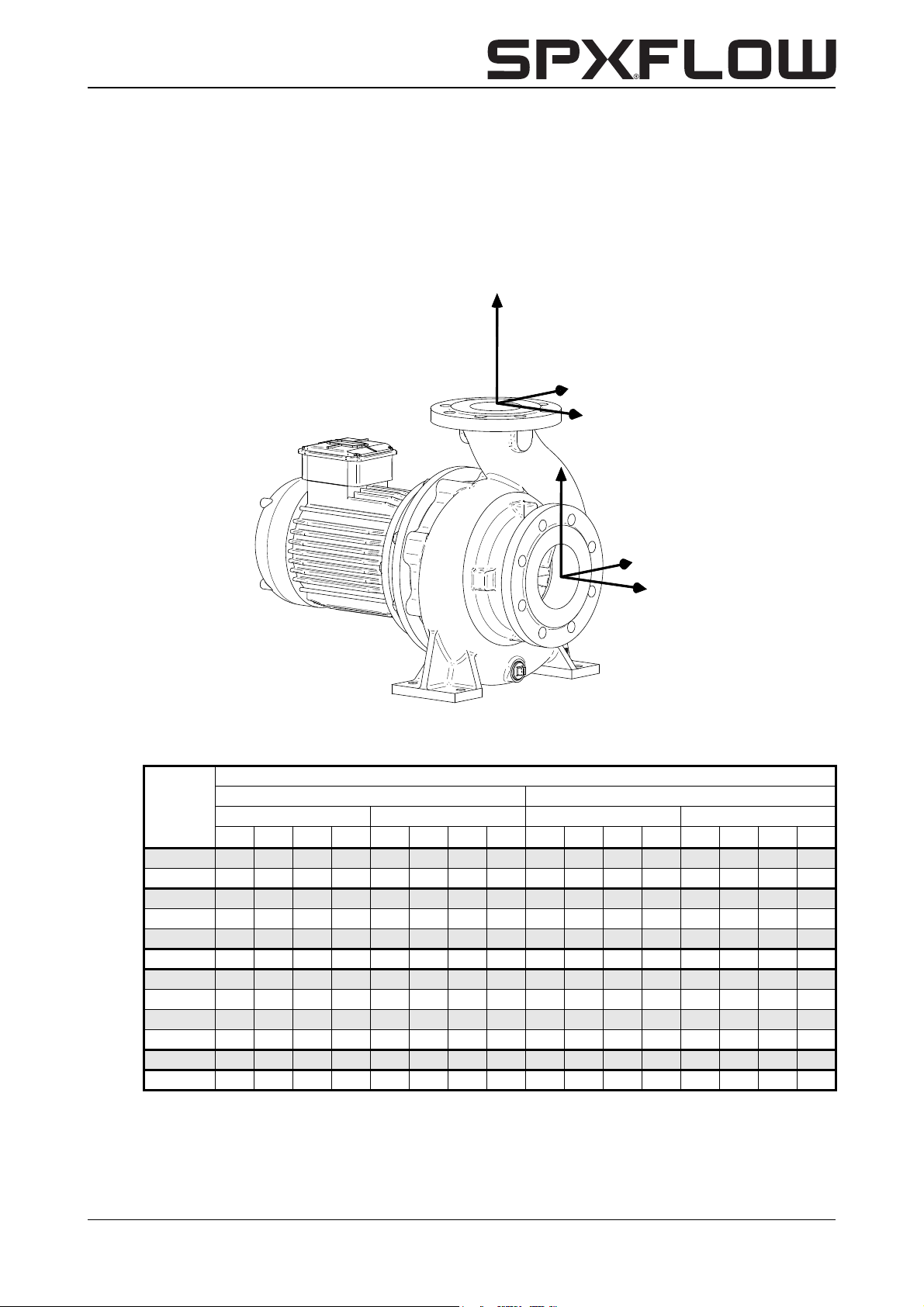
CombiLine-CombiBlocHorti
Z
Y
X
Y
X
Z
10.8 Permitted forces and torques on the flanges for CombiBlocHorti
Forces and moments acting on the pump flanges due to pipe loads can cause
misalignment of the pump, deformation and overstressing of the pump casing, or
overstressing of the fixing bolts between the pump and the baseplate.
The values can be applied simultaneously in all directions with positive or negative signs,
or separately on each flange (suction and discharge).
Figure 26: Coordinate system.
Table 8: Permitted forces and torques on the flanges.
Pump unit rigid mounted
CBH
80C-200 1050 945 1173 1838 438 508 613 910 718 875 788 1383 403 455 560 823
80-250 1050 945 1173 1838 438 508 613 910 718 875 788 1383 403 455 560 823
100-160 1243 1120 1383 2170 525 665 735 1068 945 1173 1050 1838 438 508 613 910
100C-200 1243 1120 1383 2170 525 665 735 1068 945 1173 1050 1838 438 508 613 910
100C-250 1243 1120 1383 2170 525 665 735 1068 945 1173 1050 1838 438 508 613 910
125-250 1575 1418 1750 2748 613 718 875 1278 1120 1383 1243 2170 525 665 735 1068
150-125 1575 1418 1750 2748 613 718 875 1278 1418 1750 1575 2748 613 718 875 1278
150-160 1575 1418 1750 2748 613 718 875 1278 1418 1750 1575 2748 613 718 875 1278
150-200 1575 1418 1750 2748 613 718 875 1278 1418 1750 1575 2748 613 718 875 1278
150-250 2100 1890 2345 3658 805 928 1138 1680 1418 1750 1575 2748 613 718 875 1278
200-200 2100 1890 2345 3658 805 928 1138 1680 1890 2345 2100 3658 805 928 1138 1680
250-200 2980 2700 3340 5220 1260 1460 1780 2620 2700 3340 2980 5220 1260 1460 1780 2620
Horizontal Pump, End branch, x-Axis Horizontal Pump, Top branch, z-Axis
Force [N] Moment [N.m] Force [N] Moment [N.m]
Fy Fz Fx
My Mz Mx
ΣF
ΣM
Fy Fz Fx
My Mz Mx
ΣF
ΣM
CL-CBH/EN (1901) 7.6 Technical data 69
Page 72

70 Technical data CL-CBH/EN (1901) 7.6
Page 73

CombiLine-CombiBlocHorti
Index
A
Accessories . . . . . . . . . . . . . . . . . . . . . . . . .23
Applications . . . . . . . . . . . . . . . . . . . . . . . . . 14
cooling-water systems . . . . . . . . . . . .14
greenhouses . . . . . . . . . . . . . . . . . . . . 14
hot and cold-water systems . . . . . . . .14
industrial installations . . . . . . . . . . . . . 14
utility building . . . . . . . . . . . . . . . . . . . . 14
Approved electrician . . . . . . . . . . . . . 24, 28
B
Bearings . . . . . . . . . . . . . . . . . . . . . . . . . . .27
maintenance . . . . . . . . . . . . . . . . . . . . .27
C
Cavitation . . . . . . . . . . . . . . . . . . . . . . 25, 27
Changes of temperature . . . . . . . . . . . . . .25
Commissioning . . . . . . . . . . . . . . . . . . . . . .25
D
Delivery
advice note . . . . . . . . . . . . . . . . . . . . . .10
carrier . . . . . . . . . . . . . . . . . . . . . . . . . . 10
Duty point . . . . . . . . . . . . . . . . . . . . . . . . . .25
E
Ecodesign . . . . . . . . . . . . . . . . . . . . . . . . . .15
implementing directive . . . . . . . . . . . . 15
introduction . . . . . . . . . . . . . . . . . . . . .15
MEI . . . . . . . . . . . . . . . . . . . . . . . . . . . .19
minimum efficiency . . . . . . . . . . . . . . .19
name plate . . . . . . . . . . . . . . . . . . . . . . 19
product information . . . . . . . . . . . . . . .19
pump selection . . . . . . . . . . . . . . . . . .18
Electric motor . . . . . . . . . . . . . . . . . . . . . . .15
connecting . . . . . . . . . . . . . . . . . . . . . .24
cooling air inlet . . . . . . . . . . . . . . . . . . . 23
frequency control . . . . . . . . . . . . . . . . . 15
protection class . . . . . . . . . . . . . . 15, 27
spray-water proof . . . . . . . . . . . . . . . . 27
terminal box . . . . . . . . . . . . . . . . . . . . . 24
Electricity company . . . . . . . . . . . . . . . . . . 24
Environment . . . . . . . . . . . . . . . . . . . . . . . . 27
F
Failures . . . . . . . . . . . . . . . . . . . . . . . . . . . . 28
possible causes . . . . . . . . . . . . . . . . . 29
possible solutions . . . . . . . . . . . . . . . . 30
Forklift . . . . . . . . . . . . . . . . . . . . . . . . . . . . . 11
Foundation . . . . . . . . . . . . . . . . . . . . . . . . . 23
Fuses . . . . . . . . . . . . . . . . . . . . . . . . . . . . . . 25
G
Guarantee . . . . . . . . . . . . . . . . . . . . . . . . . . 10
H
Hydraulic performance . . . . . . . . . . . . . . . . 65
I
Impeller . . . . . . . . . . . . . . . . . . . . . . . . . . . . 14
Inspection . . . . . . . . . . . . . . . . . . . . . . . . . . 25
Installation . . . . . . . . . . . . . . . . . . . . . . . . . . 24
IP 55 . . . . . . . . . . . . . . . . . . . . . . . . . . .15, 27
L
Lantern piece . . . . . . . . . . . . . . . . . . . . . . . 14
Liquid locking agents . . . . . . . . . . . . . . . . . 63
M
Maintenance staff . . . . . . . . . . . . . . . . . . 9, 10
Mechanical seal
maintenance . . . . . . . . . . . . . . . . . . . . 27
N
Name plate . . . . . . . . . . . . . . . . . . 11, 53, 62
Noise . . . . . . . . . . . . . . . . . . . . . . . . . . . . . . 27
Noise data . . . . . . . . . . . . . . . . . . . . . . . . . . 64
CL-CBH/EN (1901) 7.6 71
Page 74

P
Packaging . . . . . . . . . . . . . . . . . . . . . . . . . . 11
grips . . . . . . . . . . . . . . . . . . . . . . . . . . .11
opening . . . . . . . . . . . . . . . . . . . . . . . . . 11
straps . . . . . . . . . . . . . . . . . . . . . . . . . .11
Parts
ordering . . . . . . . . . . . . . . . . . . . . . . . .11
Performance overviews
CBH . . . . . . . . . . . . . . . . . . . . . . . . . . . 67
CL . . . . . . . . . . . . . . . . . . . . . . . . . . . . .65
Permitted forces on flanges CBH . . . . . . .69
Permitted torques on flanges CBH . . . . . . 69
Personal protection
gloves . . . . . . . . . . . . . . . . . . . . . . 11, 21
spectacles . . . . . . . . . . . . . . . . . . . . . .21
Piping . . . . . . . . . . . . . . . . . . . . . . . . . . . . . . 23
flushing . . . . . . . . . . . . . . . . . . . . . . . . . 24
Pressure impulses . . . . . . . . . . . . . . . 24, 25
Pull-out unit . . . . . . . . . . . . . . . . . . . . . . . . . 33
Pump
description . . . . . . . . . . . . . . . . . . . . . .13
in operation . . . . . . . . . . . . . . . . . . . . .25
Pump casing . . . . . . . . . . . . . . . . . . . . . . . .14
R
Re-use . . . . . . . . . . . . . . . . . . . . . . . . . . . . .21
Working switch . . . . . . . . . . . . . . . . . . . . . 24
S
Safety . . . . . . . . . . . . . . . . . . . . . . . . . . 10, 23
instructions . . . . . . . . . . . . . . . . . . . . . .10
symbols . . . . . . . . . . . . . . . . . . . . . . . .10
Scrapping . . . . . . . . . . . . . . . . . . . . . . . . . .22
Sense of rotation . . . . . . . . . . . . . . . . . . . .25
Serial number . . . . . . . . . . . . . . . . . . . . . . . 14
Shaft sleeve . . . . . . . . . . . . . . . . . . . . . . . . .14
Storage . . . . . . . . . . . . . . . . . . . . . . . . . . . . 11
System
de-aerate . . . . . . . . . . . . . . . . . . . . . . . 23
draining apertures . . . . . . . . . . . . . . . .23
T
Technicians . . . . . . . . . . . . . . . . . . . . . . . . . . 9
Tightening torques . . . . . . . . . . . . . . . . . . . 63
Transport . . . . . . . . . . . . . . . . . . . . . . . . . . .11
Type code . . . . . . . . . . . . . . . . . . . . . . . . . . 13
V
Vaporization . . . . . . . . . . . . . . . . . . . . . . . . .25
Ventilation . . . . . . . . . . . . . . . . . . . . . . . . . . 23
W
Water hammer pressure . . . . . . . . . . . . . .24
Wear ring
assembly . . . . . . . . . . . . . . . . . . . . . . .35
disassembly . . . . . . . . . . . . . . . . . . . . .34
72 CL-CBH/EN (1901) 7.6
Page 75

CombiPrime H
Horizontal self-priming centrifugal pump
CombiLine CombiBlocHorti
Circulation pumps
Johnson Pump Horticulture
De Hondert Margen 23, 2678 AC De Lier, THE NETHERLANDS
Phone: + 31 (0) 174 51 84 10 Fax: + 31 (0) 174 51 84 44
E-Mail: [email protected]
www.spxflow.com/johnson-pump
www.spxflow.com
For more information about our worldwide locations, approvals, certifications, and local representatives,
please visit www.spxflow.com/johnson-pump.
SPXFLOW Corporation reserves the right to incorporate our latest design and material changes without
notice or obligation. Design features, materials of construction and dimensional data, as described in this
bulletin, are provided for your information only and should not be relied upon unless confirmed in writing.
ISSUED 12/2015
Copyright © 2015 SPXFLOW Corporation
 Loading...