

Page 1
Instruction Manual
MCHZ(S)
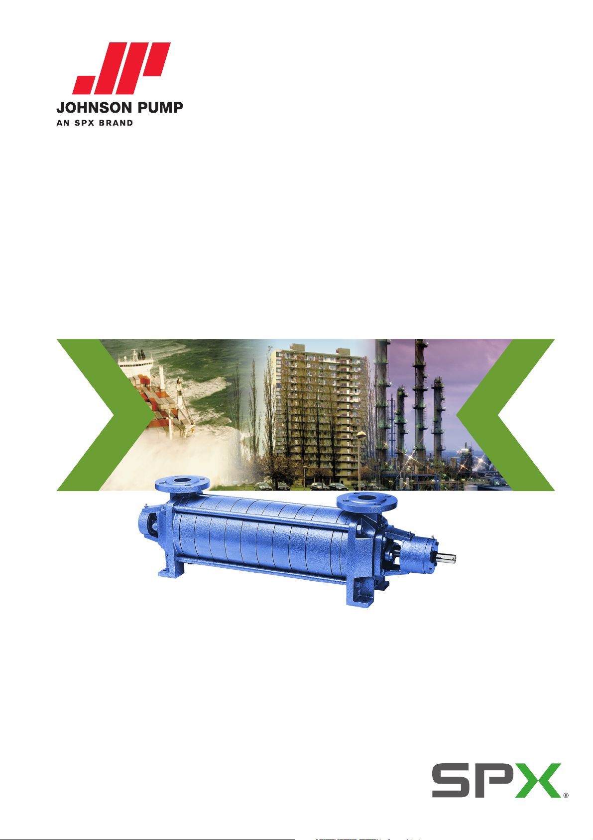
Horizontal self-priming multistage pump
Orginal instructions
Read and understand this manual prior to
operating or servicing this product.
MCHZ/EN (0912) 4.2
Page 2
EC Declaration of conformity (valid until 30-12-2009)
(Directive 98/37/EC, appendix II-A)
Manufacturer
SPX Process Equipment NL B.V.
Dr. A.F. Philipsweg 51
P.O. B ox 9
9400 AA Assen
The Netherlands
hereby declares that the pump, in case it is delivered as an assembly with drive (last
position of serial number = A), is in conformity with the provisions of Directive 98/37/EC
(as altered most recently) and the following directives and standards:
• EC directive 2006/95/EG, "Electric equipment for use within certain voltage limits"
• standards EN-ISO 12100 part 1 & 2, EN 809
The pump to which this declaration refers may only be put into operation after it has been
installed in the way prescribed by the manufacturer, and, as the case may be, after the
complete system of which this pump forms part, has been made to fulfil the requirements
of Directive 98/37/EC (as altered most recently).
Manufacturer's declaration (valid until 30-12-2009)
(Directive 98/37/EC, appendix II-B)
Manufacturer
SPX Process Equipment NL B.V.
Dr. A.F. Philipsweg 51
P.O. B ox 9
9400 AA Assen
The Netherlands
hereby declares that the pump, in case it is delivered without drive (last position of serial
number = B), is in conformity with the following standards:
• EN-ISO 12100 parts 1 & 2, EN 809
and that this pump is meant to be incorporated in or combined with another machine
(electric motor, combustion engine) and may only be put into use after the complete
machine of which the pump under consideration forms part has been made and declared
to comply with that directive.
Assen, November 1st 2009
G.A. Schaafsma,
General manager
EC/EN (0911) 5.0 1
Page 3
EC Declaration of conformity (valid from 30-12-2009)
(Directive 2006/42/EC, appendix II-A)
Manufacturer
SPX Process Equipment NL B.V.
Dr. A.F. Philipsweg 51
9403 AD Assen
The Netherlands
hereby declares that all pumps member of productfamilies
CombiChem, CombiDirt, CombiFlex(U)(B), CombiPrime H, CombiLine, CombiLineBloc,
CombiMag, CombiMagBloc, CombiNorm, CombiPro(M)(V), CombiPrime V, CombiSump,
CombiWell, FRE, FRES, FREF, FREM, KGE(L), KGEF, HCR, MCH(W)(S), MCHZ(W)(S),
MCV)(S), PHA, MDR whether delivered without drive (last position of serial number = B),
or delivered as an assembly with drive (last position of serial number = A), are in
conformity with the provisions of Directive 2006/42/EC (as altered most recently) and
where applicable the following directives and standards:
• EC directive 2006/95/EG, "Electric equipment for use within certain voltage limits"
• standards EN-ISO 12100 part 1 & 2, EN 809
The pumps to which this declaration refers may only be put into operation after they have
been installed in the way prescribed by the manufacturer, and, as the case may be, after
the complete system of which these pumps form part, has been made to fulfil the
requirements of Directive 2006/42/EC (as altered most recently).
CombiBloc, CombiBlocHorti,
Declaration of incorporation (valid from 30-12-2009)
(Directive 2006/42/EC, appendix II-B)
Manufacturer
SPX Process Equipment NL B.V.
Dr. A.F. Philipsweg 51
9403 AD Assen
The Netherlands
hereby declares that the partly completed pump (Back-Pull-Out unit), member of
productfamilies
CombiPrime H, CombiLine, CombiLineBloc, CombiMag, CombiMagBloc, CombiNorm,
CombiPro(M)(V), CombiPrime V, FRE, FRES, FREF, FREM, KGE(L), KGEF, HCR, PHA, MDR
in conformity with the following standards:
• EN-ISO 12100 parts 1 & 2, EN 809
and that this partly completed pump is meant to be incorporated into the specified pump
unit and may only be put into use after the complete machine of which the pump under
consideration forms part has been made and declared to comply with that directive.
Assen, November 1st 2009
CombiBloc, CombiBlocHorti, CombiChem, CombiDirt, CombiFlex(U)(B),
is
G.A. Schaafsma,
General Manager
2 EC/EN (0911) 5.0
Page 4
MCHZ
Instruction manual
MCHZ(S)
All technical and technological information in this manual as well as possible drawings
made available by us remain our property and shall not be used (otherwise than for the
operation of this pump), copied, duplicated, made available to or brought to the notice of
third parties without our prior written consent.
SPX Process Equipment NL B.V. (hereafter called Johnson Pump) is part of SPX
Process Equipment AB. The core activities of SPX Process Equipment AB are the
development, production, sale and maintenance of pumps and pump units.
SPX Process Equipment NL B.V.
P.O. B ox 9
9400 AA Assen
The Netherlands
Tel. +31 (0)592 376767
Fax. +31 (0)592 376760
www.johnson-pump.com or www.spxpe.com
© 2008 SPX Process Equipment NL B.V.
MCHZ/EN (0912) 4.2 3
Page 5
4 MCHZ/EN (0912) 4.2
Page 6
MCHZ
Table of Contents
1 Introduction 9
1.1 Preface 9
1.2 Safety 9
1.3 Guarantee 10
1.4 Inspection of delivered items 10
1.5 Instructions for transport and storage 10
1.5.1 Dimensions and weight 10
1.5.2 Use of pallets 10
1.5.3 Hoisting 11
1.5.4 Storage 11
1.6 Ordering parts 12
2 General 13
2.1 Pump description 13
2.2 Applications 13
2.3 Type code 14
2.4 Serial number 14
2.5 Liquids 15
2.6 Construction 15
2.6.1 Pump section 15
2.6.2 Self-priming section 15
2.6.3 Impellers 15
2.6.4 Bearing construction 15
2.6.5 Shaft seal 16
2.7 Application area 16
2.8 Re-use 16
2.9 Scrapping 16
3Installation 17
3.1 Safety 17
3.2 Preservation 17
3.3 Environment 17
3.4 Piping 18
3.5 Accessories 18
3.6 Installation 19
3.6.1 Piping 19
3.6.2 Installation of a pump unit 19
3.6.3 Assembling a pump unit 19
3.6.4 Alignment of the coupling 19
3.6.5 Tolerances for aligning the coupling 20
MCHZ/EN (0912) 4.2 5
Page 7
3.7 Connection of the electric motor 20
4 Commissioning 21
4.1 Inspection of the pump 21
4.2 Inspection of the motor 21
4.3 Preparing the pump unit for commissioning 21
4.4 Checking the sense of rotation 21
4.5 Start-up 22
4.6 Adjustment of shaft sealing 22
4.6.1 Stuffing box packing 22
4.6.2 Mechanical seal 22
4.7 Pump in operation 22
4.8 Noise 22
5 Maintenance 23
5.1 Daily maintenance 23
5.2 Shaft sealing 23
5.2.1 Stuffing box packing 23
5.2.2 Mechanical seal 23
5.3 Environmental influences 23
5.4 Lubrication of the bearings 24
5.4.1 MCHZ(S) 12,5 - 14a/b (standard bearings) - 20a/b 24
5.4.2 MCHZ(S) 16 24
5.4.3 MCHZ(S) 14a/b with heavy bearing construction 24
5.5 Noise 24
5.6 Faults 24
6 Problem solving 25
7 Disassembly and assembly 27
7.1 Special tools 27
7.2 Precautionary measures 27
7.2.1 Switch off the power supply 27
7.2.2 Pipe support 27
7.2.3 Draining the liquid 27
7.3 Disassembling the MCHZ(S)12,5-14a/b-16 28
7.3.1 Replacing the stuffing box packing MCHZ 28
7.3.2 Replacing the mechanical seal MCHZS 29
7.3.3 Disassembling the pump 29
7.3.4 Disassembling the bearing housing on the drive side 29
7.3.5 Disassembly of the ball bearing 29
7.3.6 Disassembling the mechanical seal MCHZS 29
7.3.7 Disassembling the set of stage casings 30
7.3.8 Disassembling the bearing housing on the suction side 30
7.3.9 Disassembling the ball bearing on the suction side 30
7.3.10 Disassembling the mechanical seal on the MCHZS suction side 30
7.4 Assembly 31
7.4.1 Preparation for assembly 31
7.4.2 Sub-assembly of stage casings 31
7.4.3 Pump assembly 31
7.4.4 Assembling the stuffing box packing MCHZ 32
7.4.5 Assembling the mechanical seal MCHZS 32
7.4.6 Assembling the bearing construction 33
7.4.7 Assembling the stage set 34
7.5 Disassembling MCHZ(S) 14a/b heavy bearing construction 35
7.5.1 Replacing the stuffing box packing MCHZ 35
6 MCHZ/EN (0912) 4.2
Page 8
MCHZ
7.5.2 Replacing the mechanical seal MCHZS 35
7.5.3 Disassembling the pump 35
7.5.4 Disassembling the bearing housing on the drive side 35
7.5.5 Disassembling the ball bearings 36
7.5.6 Disassembling the mechanical seal MCHZS 36
7.5.7 Disassembling the set of stage casings 36
7.5.8 Disassembling the bearing housing on the suction side 36
7.5.9 Disassembling the ball bearing on the suction side 36
7.5.10 Disassembling the mechanical seal on the MCHZS suction side 36
7.6 Assembling the MCHZ(S)14a/b heavy bearing construction 37
7.6.1 Preparation for assembly 37
7.6.2 Sub-assembly of stage casings 37
7.6.3 Pump assembly 37
7.6.4 Assembling the stuffing box packing MCHZ 37
7.6.5 Assembling the mechanical seal MCHZS 38
7.6.6 Assembling the bearing construction on the drive side 39
7.6.7 Assembling the stage set 40
7.6.8 Assembling the bearing construction on the suction side 40
7.7 Disassembling the MCHZ(S)20a/b 41
7.7.1 Replacing the stuffing box packing MCHZ 41
7.7.2 Replacing the mechanical seal MCHZS 41
7.7.3 Disassembling the MCHZ(S) 41
7.7.4 Disassembling the bearing housing on the drive side 41
7.7.5 Disassembly of the ball bearing 42
7.7.6 Disassembling the mechanical seal MCHZS 42
7.7.7 Disassembling the set of stage casings 42
7.7.8 Disassembling the bearing housing on the suction side 42
7.7.9 Disassembling the ball bearing on the suction side 42
7.7.10 Disassembling the mechanical seal on the MCHZS suction side 42
7.8 Assembling the MCHZ(S) 20a/b 43
7.8.1 Preparation for assembly 43
7.8.2 Sub-assembly of stage casings 43
7.8.3 Pump assembly 43
7.8.4 Assembling the stuffing box packing MCHZ 44
7.8.5 Assembling the mechanical seal MCHZS 44
7.8.6 Assembling the bearing construction 45
7.8.7 Assembling the stage set 46
8Dimensions 47
8.1 Dimensions MCHZ(S) 12,5 48
8.2 Dimensions MCHZ(S) 14a/b 49
8.3 Dimensions MCHZ(S) 16 50
8.4 Dimensions MCHZ(S) 20 51
8.5 Dimensions of unit MCHZ(S) 12,5 52
8.6 Dimensions of unit MCHZ(S) 14a 53
8.7 Dimensions of unit MCHZ(S) 14b 54
8.8 Dimensions of unit MCHZ(S) 16 55
8.9 Dimensions of unit MCHZ(S) 20a 56
8.10 Dimensions of unit MCHZ(S) 20b 57
9Parts 59
9.1 Ordering parts 59
9.1.1 Order form 59
9.1.2 Recommended spare parts 59
9.2 Designs 59
MCHZ/EN (0912) 4.2 7
Page 9
9.3 MCHZ 12,5 - 14a/b - 16 60
9.4 MCHZS 12,5 - 14a/b - 16 62
9.5 MCHZ 14a/b with heavy bearing construction 64
9.6 MCHZS 14a/b with heavy bearing construction 66
9.7 MCHZ 20a/b 69
9.8 MCHZS 20a/b 71
10 Technical data 73
10.1 Maximum speed 73
10.2 Permissible pressure and temperature 74
10.3 Hydraulic performance 75
10.3.1 Performance overview 3000 min-1 75
10.3.2 Performance overview 3600 min-1 76
10.4 Tightening moments for bolts and nuts 77
10.5 Tie rod torque 77
10.6 Post-greasing of ball bearings 77
10.7 Recommended locking liquids 77
10.8 Noise data 78
10.8.1 Pump noise as a function of pump power 78
10.8.2 Noise level of entire pump unit 79
Index 81
Order form for spare parts 83
8 MCHZ/EN (0912) 4.2
Page 10
MCHZ
1 Introduction
1.1 Preface
This manual is intended for technicians and maintenance staff and for those who are in
charge of ordering spare parts.
This manual contains important and useful information for the proper operation and
maintenance of this pump. It also contains important instructions to prevent potential
accidents and damage, and to ensure safe and fault-free operation of this pump.
! Read this manual carefully before commissioning the pump, familiarize
yourself with the operation of the pump and strictly obey the instructions!
The data published here comply with the most recent information at the time of going to
press. However they may be subject to later modifications.
Johnson Pump reserves the right to change the construction and design of the products
at any time without being obliged to change earlier deliveries accordingly.
1.2 Safety
This manual contains instructions for working safely with the pump. Operators and
maintenance staff must be familiar with these instructions.
Below is a list of the symbols used for those instructions and their meaning:
Personal danger for the user. Strict and prompt observance of the
corresponding instruction is imperative!
! Risk of damage or poor operation of the pump. Follow the corresponding
instruction to avoid this risk.
➢ Useful instruction or tip for the user.
Items which require extra attention are shown in bold print.
This manual has been compiled by Johnson Pump with the utmost care. Nevertheless
Johnson Pump cannot guarantee the completeness of this information and therefore
assumes no liability for possible deficiencies in this manual. The buyer/user shall at all
times be responsible for testing the information and for taking any additional and/or
deviating safety measures. Johnson Pump reserves the right to change safety
instructions.
MCHZ/EN (0912) 4.2 Introduction 9
Page 11
1.3 Guarantee
Johnson Pump shall not be bound to any guarantee other than the guarantee accepted
by Johnson Pump. In particular, Johnson Pump will not assume any liability for explicit
and/or implicit guarantees such as but not limited to the marketability and/or suitability of
the products supplied.
The guarantee will be cancelled immediately and legally if:
• Service and/or maintenance is not undertaken in strict accordance with the
instructions.
• The pump is not installed and operated in accordance with the instructions.
• Necessary repairs are not undertaken by our personnel or are undertaken without our
prior written permission.
• Modifications are made to the products supplied without our prior written permission.
• The spare parts used are not original Johnson Pump parts.
• Additives or lubricants used are other than those prescribed.
• The products supplied are not used in accordance with their nature and/or purpose.
• The products supplied have been used amateurishly, carelessly, improperly and/or
negligently.
• The products supplied become defective due to external circumstances beyond our
control.
All parts which are liable to wear are excluded from guarantee. Furthermore, all
deliveries are subject to our “General conditions of delivery and payment”, which will be
forwarded to you free of charge on request.
1.4 Inspection of delivered items
Check the consignment immediately on arrival for damage and conformity with the advice
note. In case of damage and/or missing parts, have a report drawn up by the carrier at
once.
1.5 Instructions for transport and storage
1.5.1 Dimensions and weight
A pump or a pump unit is generally too heavy to be moved by hand. Therefore, use the
correct transport and lifting equipment. Dimensions and weight of the pump or pump unit
are shown on the label on the cover of this manual.
1.5.2 Use of pallets
Usually a pump or pump unit is shipped on a pallet. Leave it on the pallet as long as
possible to avoid damages and to facilitate possible internal transport.
! When using a forklift always set the forks as far apart as possible and lift the
package with both forks to prevent it from toppling over! Avoid jolting the
pump when moving it!
10 Introduction MCHZ/EN (0912) 4.2
Page 12
MCHZ
1.5.3 Hoisting
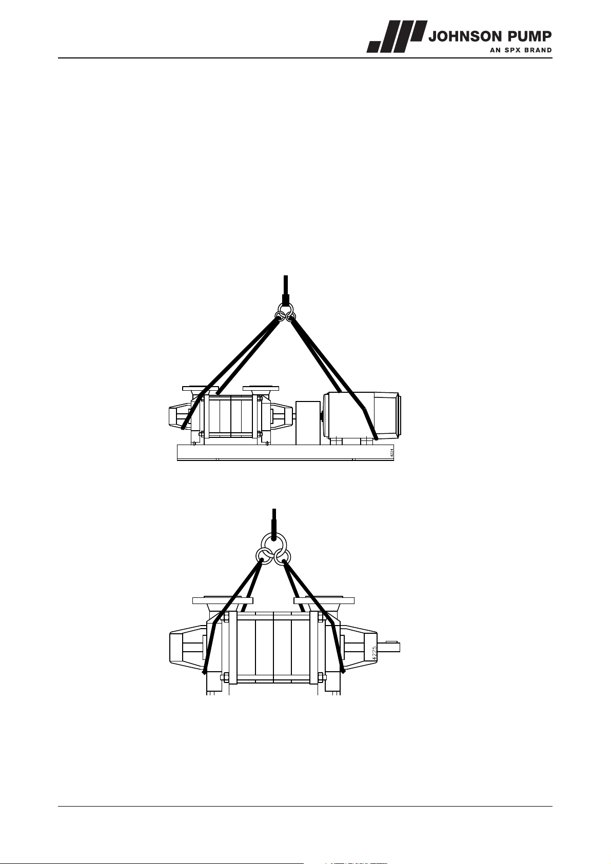
When hoisting a pump or complete pump units the straps must be fixed in accordance
with figure 1 and figure 2.
When lifting a pump or a complete pump unit always use a proper and sound
lifting device, approved to bear the total weight of the load!
Never go underneath a load that is being lifted!
! If the electric motor is provided with a lifting eye, this lifting eye is intended
only for the purpose of carrying out service activities to the electric motor!
The lifting eye is designed to bear the weight of the electric motor only!
It is NOT permitted to lift a complete pump unit at the lifting eye of an electric
motor!
Figure 1: Lifting instructions for pump unit.
Figure 2: Lifting instructions for single pump.
1.5.4 Storage
If the pump is not to be used immediately the pump shaft must be turned by hand twice
per week.
MCHZ/EN (0912) 4.2 Introduction 11
Page 13
1.6 Ordering parts
This manual contains a survey of the spare parts recommended by Johnson Pump as well
as the instructions for ordering them. A fax-order form is included in this manual.
You should always state all data stamped on the type plate when ordering parts and in
any other correspondence regarding the pump.
➢ This data is also printed on the label on the front of this manual.
If you have any questions or require further information with regard to specific subjects,
then do not hesitate to contact Johnson Pump.
12 Introduction MCHZ/EN (0912) 4.2
Page 14
MCHZ
2 General
2.1 Pump description
The MCHZ is a range of horizontal high-pressure stage pumps with closed impellers.
The range consists of the following 6 basic types:
• MCHZ 12,5
• MCHZ 14a
• MCHZ 14b
•MCHZ 16
• MCHZ 20a
• MCHZ 20b
Each basic type can be designed with one or more pressure stages.
Flange dimensions, bolt circle and number of holes are according DIN 2535 ND 40.
The pump is driven by a standard IEC foot motor. The power is transmitted through a
flexible coupling.
Due to the modular design of the construction parts there is a high level of
interchangeability, even with other types of multistage pumps, such as the MCV or the
MCH.
2.2 Applications
The pump can be used for the following applications:
• warm and hot water supply systems.
• air-conditioning.
• cooling for land and marine installations.
• water supply for industry, water supply companies, agriculture and horticulture.
• spraying installations.
• washing and condensing installations.
• pressure increasing installations.
• in the process industry, general industry, road and marine construction.
MCHZ/EN (0912) 4.2 General 13
Page 15
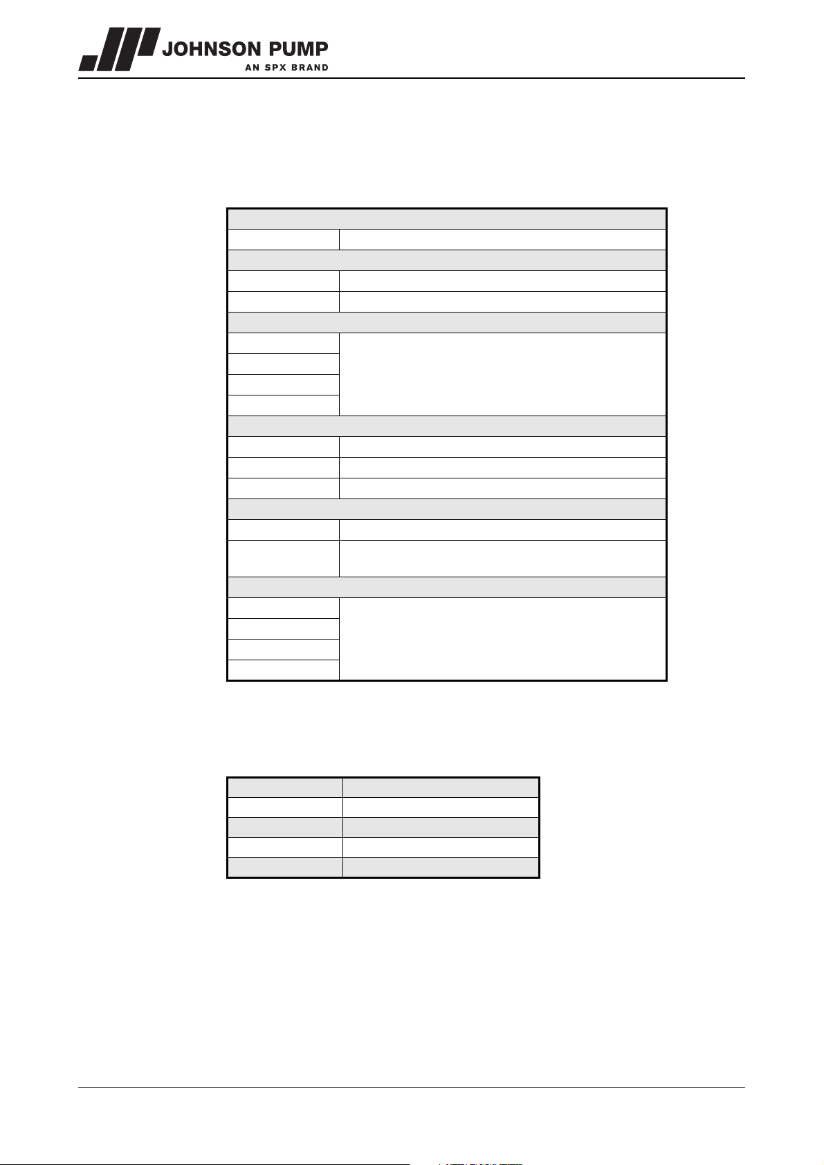
2.3 Type code
Pumps are available in various designs. The main characteristics of the pump are shown
in the type code.
Examples: MCHZ 12,5 x n - 3,2 or MCHZS 20a x n - 8
MCHZ
S
12,5
14
16
20
a
b
n
n,7
3,2
5
6,5
8
Pump family
Multi stage Centrifugal Horizontal Z (Self-priming)
Shaft sealing
stuffing box packing
mechanical seal
Impeller diameter
impeller diameter in cm
Impeller width
standard impeller
narrow impeller
wide impeller
Number of stages
number of stages
n+1 impellers, of which the first has a reduced
diameter (70% of full diameter in this example)
Connections
diameter suction and pressure connection in cm
2.4 Serial number
Serial number of the pump or pump unit are shown on the name plate off the pump and
on the label on the cover of this manual.
Example: 01-1000675A
01 year of manufacture
100067 unique number
5 number of pumps
Apump with motor
B pump with free shaft end
14 General MCHZ/EN (0912) 4.2
Page 16
MCHZ
2.5 Liquids
In general the MCHZ pumps are suitable for pumping clean liquids, such as:
• spring water, cold and hot water.
• various cooling liquids.
• caustic soda.
• petrol, kerosene, petroleum.
These liquids must not affect the materials used. For the materials used see the
appropriate parts list in chapter 9.
We advise against using the pump for an application which differs from that
for which the pump was originally supplied, without discussing this with your
supplier first! Using a pump in a system or under system conditions (liquid,
system pressure, temperature, etc.) for which it has not been designed can
create danger for the user!
2.6 Construction
2.6.1 Pump section
The pump section is assembled from an inlet and outlet casing and a number of sections
or stage casings with cast vanes. The inlet and outlet casings are fitted with a cast
suction and pressure flange. The support for the inlet and outlet casings are in a vertical
centre line with the suction and the pressure pipes.
The inlet and outlet casings are fitted with connections for pressure gauge, balance pipe,
possible barrier liquid and drain.
By using guide blades the radial forces on the rotor can be disregarded over the entire
capacity curve.
The stage casings are fitted with exchangeable wear rings. To prevent turbulence and for
the benefit of the required NPSH values, there is a suction cover with 2 anti-rotation
partitions located in front of the first impeller.
2.6.2 Self-priming section
The self-priming section contains a built-in vacuum pump which operates according to
the liquid ring principle. Air or gas which is sucked in is discharged immediately via the
pressure pipe, provided there is no back-pressure.
2.6.3 Impellers
All types of MCHZ pumps, are fitted with closed impellers, designed with 2 sealing
edges and balance holes. As a result of this the axial forces on the rotor are reduced to a
minimum. The remaining forces are taken up by an axially mounted bearing. The impellers
are held on the shaft by 2 stainless steel external circlips.
2.6.4 Bearing construction
• All MCHZ pumps are designed with 2 grease-lubricated deep-groove ball bearings.
• For the types MCHZ 20a and 20b a double-row angular contact bearing is used on
the pressure side.
• Pumps with heavy bearing constructions - used for MCHZ 14a and 14b - are fitted
with 2 single-row angular contact bearings on the pressure side.
• MCHZ(S) 12,5, 14a/b (with standard bearings) and 20a/b are provided with 2RS1bearings.
• The MCHZ 16 and MCHZS 16 are fitted with grease nipples so that these bearings
can be greased periodically.
• The bearing housings are fitted with 2 holes so that the stuffing box is easy to access.
MCHZ/EN (0912) 4.2 General 15
Page 17
• The bearing on the pressure side is axially fixed.
• The bearing is sealed by means of rubber V-rings.
2.6.5 Shaft seal
The shaft seal for the MCHZ is available in 2 variants:
1MCHZ
Standardized stuffing box packing rings.
Pumps for which the pressure in the stuffing box becomes too high are designed with
a balance pipe.
2MCHZS
Mechanical seal with bellows
Cooling and lubrication of this seal is undertaken by circulation of the pumped liquid
via a balance pipe.
2.7 Application area
The application area globally looks as follows:
Capacity
Discharge head 340 m
Suction head
However, the maximum allowable pressures and temperatures depend strongly on the
selected materials and components. Also working conditions may cause differences. For
more detailed information see paragraph 10.2 "Permissible pressure and temperature".
Maximum value
100 m3/h
8 m (for water of 15°C and provided that air which is drawn
in is discharged without back-pressure)
2.8 Re-use
The pump may only be used for other applications after prior consultation with Johnson
Pump or your supplier. Since the lastly pumped medium is not always known, the
following instructions should be observed:
• Flush the pump properly
• Make sure the flushing liquid is discharged safely (environment!)
Take adequate precautions and use the appropriate personal protection
means (rubber gloves, spectacles)!
2.9 Scrapping
If it has been decided to scrap a pump, the same procedure as for paragraph 2.8 "Reuse" should be followed.
16 General MCHZ/EN (0912) 4.2
Page 18
MCHZ
3Installation
3.1 Safety
• Read this manual carefully prior to installation and commissioning. Non-observance of
these instructions can result in serious damage to the pump and this will not be
covered under the terms of our guarantee. Follow the instructions given step by step.
• Ensure that the pump can not be started if work has to be undertaken to the pump
during installation and the rotating parts are insufficiently guarded.
• Depending on the design the pumps are suitable for liquids with a temperature of up
to 120°C. When installing the pump unit to work at 70°C and above the user should
ensure that appropriate protection measures and warnings are fitted to prevent
contact with the hot pump parts.
• If there is danger of static electricity, the entire pump unit must be earthed.
• If the pumped liquid is harmful to men or the environment, take appropriate measures
to drain the pump safely. Possible leakage liquid from the shaft seal should also be
discharged safely.
3.2 Preservation
In order to prevent corrosion, the inside of the pump is treated with a preserving agent
before leaving the factory. Before commissioning the pump remove any preserving
agents and flush the pump thoroughly with hot water.
3.3 Environment
• The foundation must be hard, level and flat.
• The area in which the pump is installed must be sufficiently ventilated. An ambient
temperature or air humidity which is too high, or a dusty environment, can have a
detrimental effect on the operation of the electric motor.
• There should be sufficient space around the pump unit to operate and if necessary
repair it.
• Behind the cooling air inlet of the motor there must be a free area of at least ¼ of the
electric motor diameter, to ensure unobstructed air supply.
• For models with a stuffing box, check that the gland nuts have not been overtightened. If necessary slacken the gland nuts and re-tighten them by hand.
MCHZ/EN (0912) 4.2 Installation 17
Page 19
3.4 Piping
• The piping to the suction and delivery connections must fit exactly and must not be
subject to stress during operation.
• The passage of the suction pipe must be amply dimensioned. This pipe should be as
short as possible and run towards the pump in such a way that no air pockets can
arise. If this is not possible, a venting facility should be provided at the highest point of
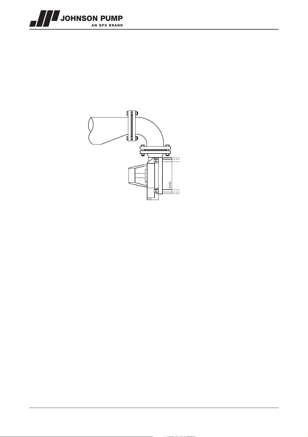
the pipe. If the inside diameter of the suction pipe is larger than the suction connection
of the pump, an eccentric reducer should be applied to prevent air pockets and whirls
See figure 3.
Figure 3: Eccentric reducer to suction flange.
• The maximum allowable system pressure is stated in paragraph 10.2 "Permissible
pressure and temperature". If there is a risk that this pressure might be exceeded, for
instance because of an excessive inlet pressure, appropriate measures should be
taken by mounting a safety valve in the piping.
• Sudden changes in the rate of flow can lead to high pressure impulses in the pump
and the piping (water shock). Therefore, do not use quick-acting closing devices,
valves etc.
3.5 Accessories
• Fit any parts that may have been supplied separately.
• If the liquid does not flow towards the pump, fit a foot valve at the bottom of the
suction pipe. If necessary, combine this foot valve with a suction strainer to prevent
impurities from being drawn in.
• When mounting, place temporarily (for the first 24 operating hours) a fine gauze
between suction flange and suction pipe to prevent internal pump parts from being
damaged by foreign matter. If the risk of damage continues to exist, fit a permanent
filter.
18 Installation MCHZ/EN (0912) 4.2
Page 20
MCHZ
B
A
3.6 Installation
3.6.1 Piping
Fit the gaskets between the flanges and connect the pressure and the suction pipes to
the pump.
3.6.2 Installation of a pump unit
Pump and motor shafts of complete pump units are adjusted perfectly in line in the
works.
1 In case of permanent arrangement place the base plate level on the foundation with
the aid of shims.
2 Carefully tighten the nuts on the foundation bolts.
3 Check the alignment of pump and motor shafts and if necessary realign, see
paragraph 3.6.4 "Alignment of the coupling".
3.6.3 Assembling a pump unit
If the pump and the electric motor still have to be assembled, do the following:
1 Fit both halves of the coupling to the pump shaft and the motor shaft respectively.
2 If the shaft height of the pump is not equal to the IEC size of the motor, level up the
difference by placing properly sized spacers under the pump or under the motor feet.
3 Place the pump on the base plate. Fix the pump to the base plate.
4 Place the electric motor on the base plate. Move the motor to obtain a gap of 3 mm
between both coupling halves.
5 Place copper shims under the feet of the electric motor. Fix the electric motor to the
base plate.
6 Align the coupling in accordance with the following instructions.
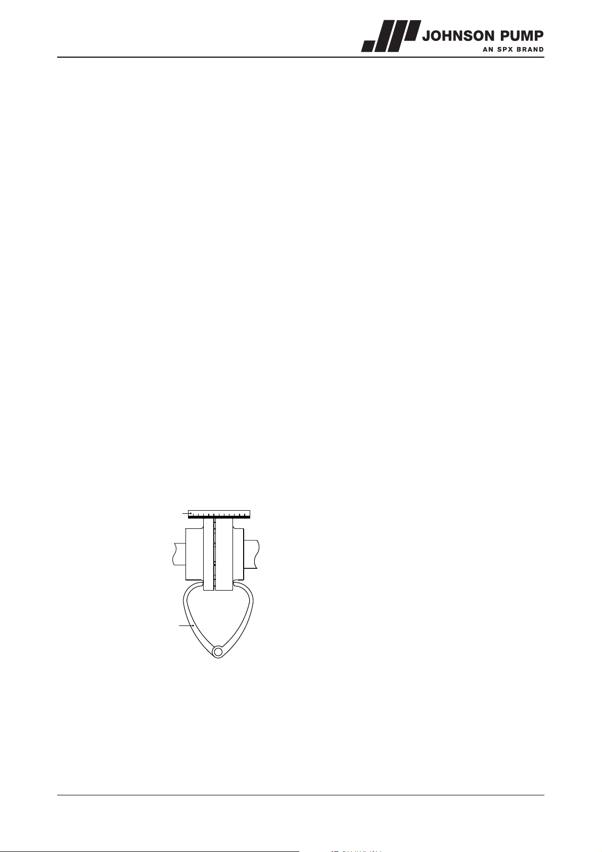
3.6.4 Alignment of the coupling
1 Place a ruler (A) on the coupling. Place or remove as many copper shims as is
necessary to bring the electric motor to the correct height so that the straight edge
touches both coupling halves over the entire length, see figure 4.
Figure 4: Aligning the coupling by means of a ruler and a pair of outside callipers.
2 Repeat the same check on both sides of the coupling at the height of the shaft. Move
the electric motor so that the straight edge touches both coupling halves over the
entire length.
3 Check the alignment once again using a pair of external callipers (B) at 2 diametrical
opposite points on the sides of the coupling halves, see figure 4.
4 Fit the guard.
MCHZ/EN (0912) 4.2 Installation 19
Page 21
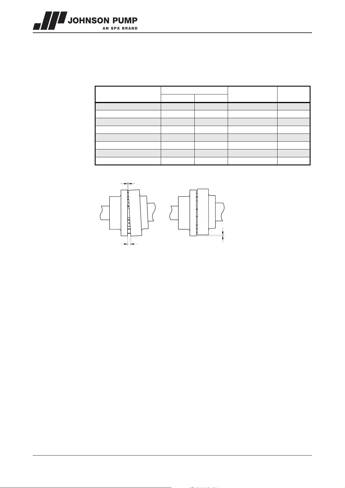
3.6.5 Tolerances for aligning the coupling
Vr
Va
max
Va
min
The maximum allowable tolerances for the alignment of the coupling halves are shown in
Table 1. See also figure 5.
Table 1: Alignment tolerances
External diameter of
coupling [mm]
V
min [mm] max [mm]
Va
max
- Va
[mm]
min
Vr
max
81-95 2 4 0,15 0,15
96-110 2 4 0,18 0,18
111-130 2 4 0,21 0,21
131-140 2 4 0,24 0,24
141-160 2 6 0,27 0,27
161-180 2 6 0,30 0,30
181-200 2 6 0,34 0,34
201-225 2 6 0,38 0,38
*) = coupling with spacer
Figure 5: Alignment tolerances standard coupling.
[mm]
3.7 Connection of the electric motor
The electric motor must be connected to the mains by an approved
electrician, according to the locally prevailing regulations of the electricity
company.
• Refer to the instruction manual belonging to the electric motor.
• If possible, mount a working switch as close as possible to the pump.
20 Installation MCHZ/EN (0912) 4.2
Page 22
MCHZ
4 Commissioning
4.1 Inspection of the pump
• Construction with stuffing box packing: check whether the gland nuts have not been
over tightened. If necessary, loosen these nuts and tighten them again by hand.
• Check whether the pump shaft turns freely. Do this by turning the shaft end at the
coupling a few times by hand.
4.2 Inspection of the motor
Pump driven by an electric motor:
• Check whether the fuses have been mounted.
4.3 Preparing the pump unit for commissioning
Proceed as follows, both when the unit is put into operation for the first time and after the
pump has been overhauled:
1 Fully open the stop valve in the suction pipe. Close the delivery stop valve.
2 Fill the pump and the suction pipe with the liquid to be pumped.
3 Turn the pump shaft a few times by hand and add more liquid, if necessary.
4.4 Checking the sense of rotation
Beware of possible non-screened rotating parts, when checking the sense of
rotation!
1 The sense of rotation of the pump is indicated by an arrow. Check whether the sense
of rotation of the motor corresponds with that of the pump.
2 Let the motor run for only a short time and check the sense of rotation.
3 If the sense of rotation is not correct, alter the sense of rotation. See the instructions
in the user manual belonging to the electric motor.
4 Fit the guard.
MCHZ/EN (0912) 4.2 Commissioning 21
Page 23
4.5 Start-up
1 Open the stop valves in the supply and return lines for flushing or cooling liquid, if the
pump is connected to a flushing or cooling system. Ensure these systems are
switched on and set at the proper values.
2 Start the pump.
3 As soon as the pump is under pressure, slowly open the delivery stop valve until the
working pressure is attained.
Make sure that when a pump is running, rotating parts are always properly
screened off by the guard!
4.6 Adjustment of shaft sealing
4.6.1 Stuffing box packing
After the pump is started, the stuffing box packing will show a certain amount of leakage.
Because of the expansion of the packing fibres, this leakage will gradually decrease.
Make sure that the stuffing box packing never runs dry. To prevent this, loosen the gland
nuts to the extent that the stuffing box packing leaks by drops. As soon as the pump has
reached the proper temperature (and leakage is still too much) the gland can be adjusted
permanently:
1 Tighten both nuts, one after the other, a quarter turn.
2 Wait 15 minutes after each adjustment before making the next adjustment.
3 Continue in this way until an acceptable leakage by drops has been attained
(10/20 cm
3
/h).
4.6.2 Mechanical seal
• A mechanical seal may never show visible leakage.
4.7 Pump in operation
When the pump is in operation, pay attention to the following:
• The pump should never run dry.
• Never use a stop valve in the suction line to control pump output. The stop valve
should always be fully opened during operation.
• Check whether the absolute inlet pressure is sufficient, to prevent vaporization in the
pump.
• Check whether the pressure difference between suction and delivery side
corresponds with the specifications of the pump's duty point.
4.8 Noise
The noise production of a pump depends to a great extent on the operating conditions.
The values stated in paragraph 10.8 "Noise data" are based on normal operation of the
pump, driven by an electric motor. In case the pump is driven by a combustion engine, or
in case it is used outside the normal operation area, as well as in case of cavitation, the
noise level may exceed 85 dB(A). In that case precautions should be taken, like building
a noise-barrier around the unit or wearing hearing protection.
22 Commissioning MCHZ/EN (0912) 4.2
Page 24
MCHZ
5 Maintenance
5.1 Daily maintenance
Regularly check the outlet pressure.
No water should get into the terminal box of the electric motor when the
pump room is sprayed clean! Never spray water on hot pump parts! The
sudden cooling down may cause them to burst and hot water may flow out!
5.2 Shaft sealing
5.2.1 Stuffing box packing
Do not tighten the gland nuts any more after the running-in period and adjustment. If in
time the stuffing box packing starts to leak excessively, new packing rings have to be
mounted instead of further tightening the nuts!
5.2.2 Mechanical seal
A mechanical seal generally requires no maintenance, however, it should never be
allowed to run dry. If there are no problems, do not dismantle the mechanical seal. As
the seal faces have run in on one another dismantling usually implicates replacement of
the mechanical seal. If a mechanical seal shows any leakage it has to be replaced.
5.3 Environmental influences
• Regularly clean the filter in the suction pipe or the suction strainer at the bottom of the
suction pipe, as the inlet pressure may become too low if the filter or the suction
strainer is fouled.
• If there is a risk that the pumped liquid expands during solidification or freezing, the
pump has to be drained and, if necessary, flushed after it has been put out of service.
• If the pump is out of service for a long time, it has to be preserved.
MCHZ/EN (0912) 4.2 Maintenance 23
Page 25
5.4 Lubrication of the bearings
5.4.1 MCHZ(S) 12,5 - 14a/b (standard bearings) - 20a/b
These pump types are provided with 2RS1 bearings which are filled with grease for their
entire duty life and which do not require any maintenance.
5.4.2 MCHZ(S) 16
The ball bearings and the ball bearing housing are filled with a quantity of grease on
delivery which is sufficient for the life of the bearing. In case the pump is overhauled, the
bearings and bearing chambers have to be cleaned and provided with new grease. See
paragraph 10.6 "Post-greasing of ball bearings" for recommended greases.
5.4.3 MCHZ(S) 14a/b with heavy bearing construction
These pump types are fitted with grease nipples so that the bearings can be greased
periodically. After every 8000 operating hours 5 grammes of grease must be added to
each bearing. In case the pump is overhauled, the bearings and bearing chambers on
drive side have to be cleaned and provided with new grease. See paragraph 10.6
"Post-greasing of ball bearings" for recommended greases.
5.5 Noise
If a pump starts making noise, this may point to certain problems with the pump unit.
A crackling noise can indicate cavitation or excessive motor noise can indicate
deterioration of the bearings.
5.6 Faults
The pump, of which you want to determine the fault, may be hot or under
pressure. Take the appropriate precautions first and protect yourself with
the proper safety devices (safety goggles, gloves, protective clothing)!
To determine the source of the malfunctioning of the pump, proceed as follows:
1 Switch off the power supply to the pump unit. Lock the working switch with a padlock
or remove the fuse.
2 Close the stop valves.
3 Determine the nature of the fault.
4 Try to determine the cause of the fault with chapter 6 "Problem solving" and take the
appropriate measures or contact your installer.
24 Maintenance MCHZ/EN (0912) 4.2
Page 26
MCHZ
6 Problem solving
Faults in a pump installation can have various causes. The fault may not be in the pump, it
may also be caused by the pipe system or the operating conditions. Firstly, always check
that installation has been executed in accordance with the instructions in this manual and
that the operating conditions still correspond with the specifications for which the pump
was purchased.
In general, breakdowns in a pump installation are attributable to the following causes:
• Faults with the pump.
• Breakdowns or faults in the pipe system.
• Faults due to incorrect installation or commissioning.
• Faults due to incorrect choice of pump.
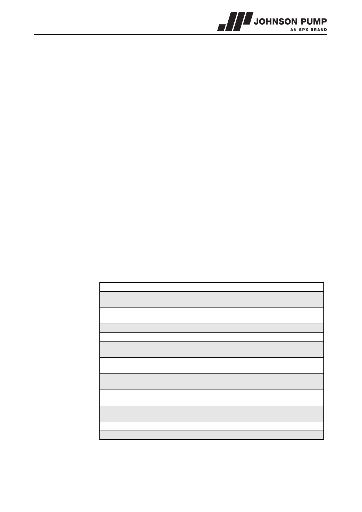
A number of the most frequently occurring failures as well as their possible causes are
shown in the table below.
Table 2: Most frequently occurring failures.
Most common faults Possible causes, see Table 3.
Pump delivers no liquid
Pump has insufficient volume flow
Pump has insufficient head 2 4 5 13 14 17 19 28 29
Pump stops after start up 1 2 3 4 5 8 9 10 11
Pump has higher power consumption than
normal
Pump has lower power consumption than
normal
The stuffing box packing is leaking
excessively
Packing rings or mechanical seal have to
be replaced to often
Pump vibrates or is noisy
Bearings wear too much or become hot 23 24 25 26 27 37 38 39 40 42
Pump running rough hot or seizes 23 24 25 26 27 34 37 38 39 40 42
1 2 3 4 5 8 9 10 11 13 14 17 19 20 21
29
1 2 3 4 5 8 9 10 11 13 14 15 17 19 20
21 28 29
12 15 16 17 18 22 23 24 25 26 27 32
34 38 39
13 14 15 16 17 18 20 21 28 29
23 25 26 30 31 32 33 43
23 25 26 30 32 33 34 41
1 9 10 11 15 18 19 20 22 23 24 25 26
27 29 37 38 39 40
MCHZ/EN (0912) 4.2 Problem solving 25
Page 27
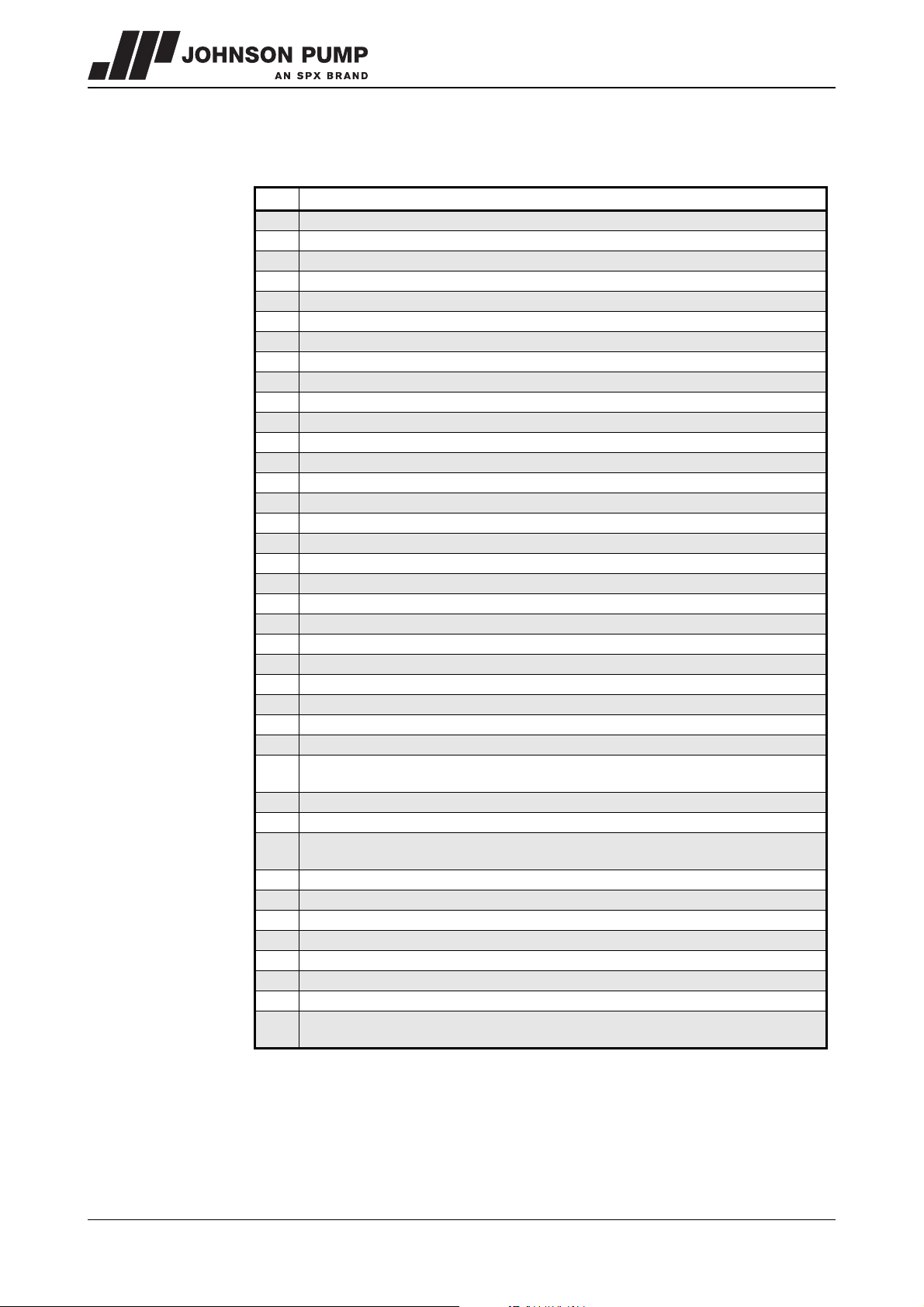
Table 3: Possible causes of pump failures.
Possible causes
1 Pump or suction pipe is not sufficiently filled or de-aerated
2 Gas or air coming from the liquid
3 Air lock in the suction pipe
4 Air leak in the suction pipe
5 The pump takes in air through the stuffing box packing
8 The manometric suction head is too high
9 Suction pipe or suction strainer is blocked
10 Insufficient immersion of foot valve or suction pipe during operation of the pump
11 NPSH available too low
12 Speed too high
13 Speed too low
14 Wrong sense of rotation
15 Pump does not operate at the right duty point
16 Liquid density differs from the calculated liquid density
17 Liquid viscosity differs from the calculated liquid viscosity
18 Pump operates when the liquid flow is too low
19 Wrong pump selection
20 Obstruction in impeller or pump casing
21 Obstruction in the piping
22 Wrong installation of the pump unit
23 Pump and motor not well aligned
24 Rotating part running out of true
25 Imbalance in rotating parts (for instance: impeller or coupling)
26 Pump shaft is running out of true
27 Bearings faulty or worn out
28 Casing wear rings faulty or worn out
29 Damaged impeller
30 Shaft on the spot of the stuffing box packing rings or seal faces of the mechanical seal
are worn out or damaged
31 Worn out or dried out stuffing box packing rings
32 Not well packed stuffing box packing or bad mounting of the mechanical seal
33 Stuffing box packing type or mechanical seal not suitable for the pumped liquid or
operation circumstances
34 Gland or mechanical seal cover has been tightened too much or crookedly
37 Axial retaining of impellers or pump shaft is defective
38 The bearings have been mounted wrongly
39 Too much or too little bearing lubrication
40 Wrong or polluted lubricant
41 Impurities in the liquid get into the stuffing box packing
42 Too high axial force because of excessive inlet pressure
43 Excessive pressure in stuffing box packing space due to too much play in the throttling
bush or blocked by-pass
26 Problem solving MCHZ/EN (0912) 4.2
Page 28
MCHZ
7 Disassembly and assembly
7.1 Special tools
Assembly and disassembly work requires no special tools. However, such tools can
make certain jobs easier, for instance replacing the shaft seal. If such is the case it will be
indicated in the text.
7.2 Precautionary measures
Before the pump can be repaired it must first be dismantled. The following measures are
required for this:
7.2.1 Switch off the power supply
1 Switch off the power supply to the pump by placing the pump switch on the control
box to the "OFF" position, or if an operating switch is fitted by turning this "OFF".
2 Remove the fuses.
3 Fit a warning board onto the control box.
7.2.2 Pipe support
If the entire pump has to be removed check that the pipes are supported. If this is not the
case, then ensure sufficient support and fixing points for the pipes first.
7.2.3 Draining the liquid
If the liquid being pumped is hot, then allow the pump to cool down further
before proceeding. Make sure you do not come into contact with the
pumped liquid if this is hot or of an unknown composition!
1 Close any relevant stop cocks.
2 Drain the pump until no more liquid flows out.
An MCHZ(S) pump can not be drained fully in the horizontal position. If
possible place the pump vertically on the bearing cover and allow it to drain
further.
MCHZ/EN (0912) 4.2 Disassembly and assembly 27
Page 29
7.3 Disassembling the MCHZ(S)12,5-14a/b-16
4044
Make sure that the power supply to the pump is switched off and that no one
can switch the pump on again unintentionally!
If there is no illustration with the instruction, the item numbers used relate to the
illustrations in the parts list for this pump, in chapter 9.
7.3.1 Replacing the stuffing box packing MCHZ
If the pump has to be further dismantled then replacement of the packing rings will be
easier if the bearing housings (0010) are removed.
If only the packing rings have to be replaced then the pump does not need to be
disconnected from the pipe work and it can remain on the foundation. Proceed as
follows, this applies for both sides of the pump:
1 Remove the gland nuts (0280) and pull the gland (0120) backwards.
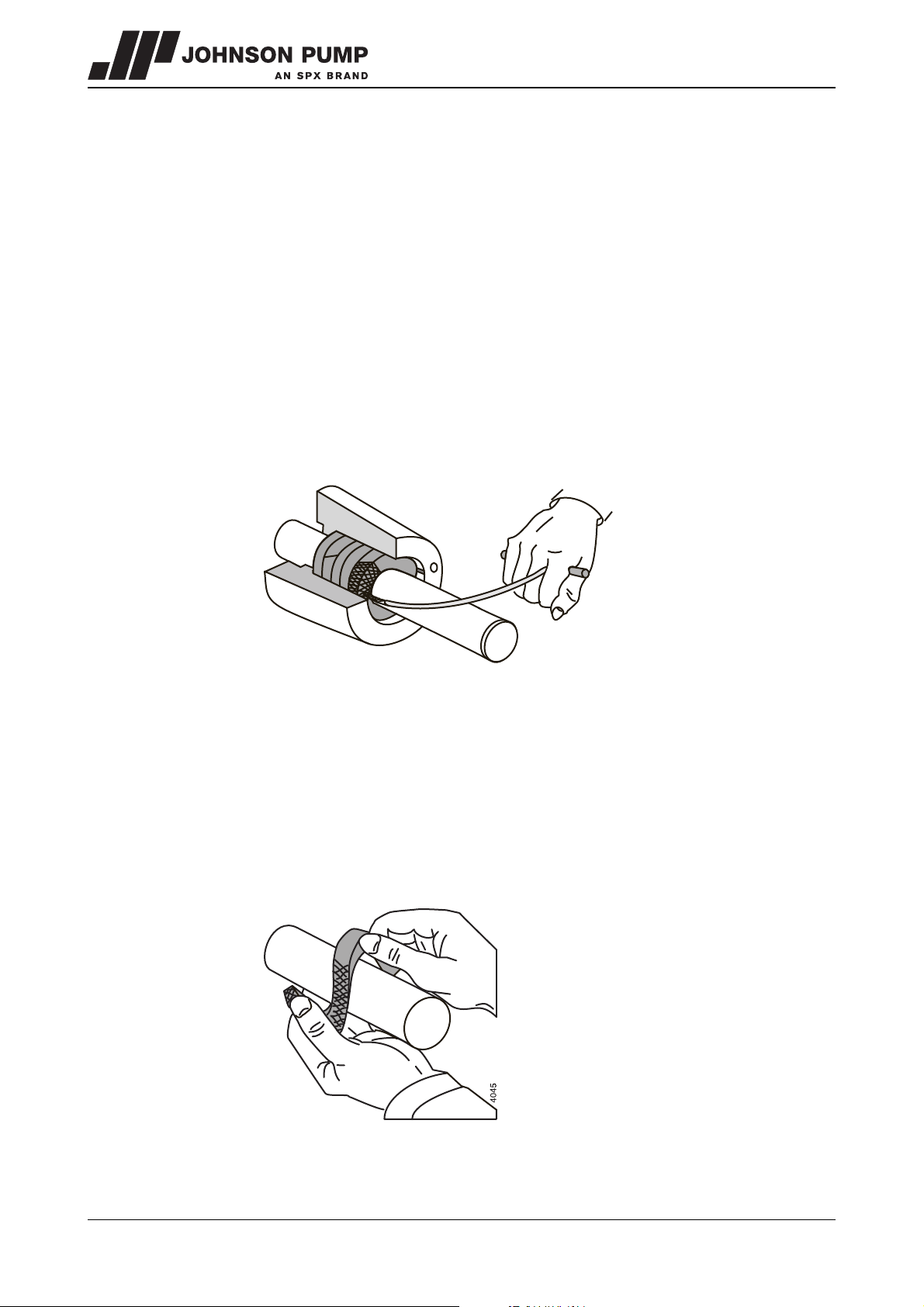
2 Remove the packing rings (0140) from the stuffing box. Use the special packing
puller for this, see figure 6.
Figure 6: Removing stuffing box packing rings.
3 Clean the stuffing box and then grease it with graphite grease or silicone grease. Also
grease the new packing rings.
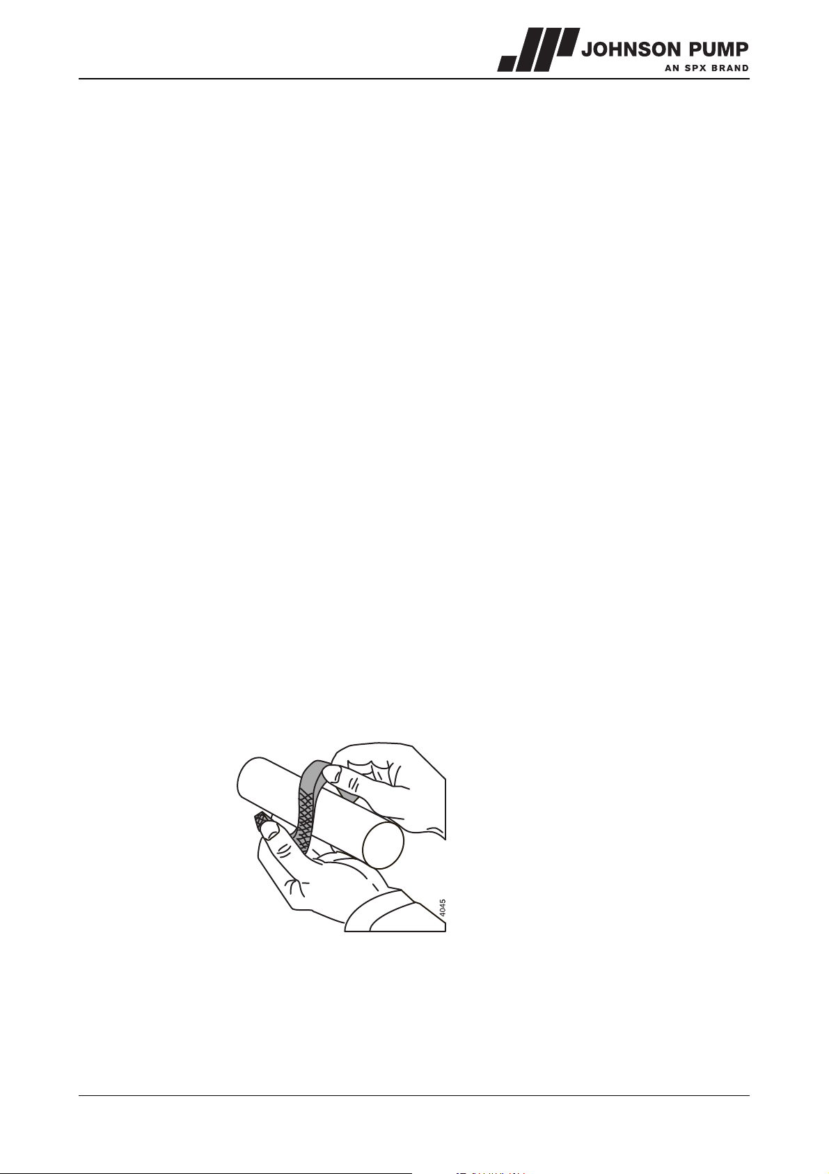
4 Bend open the first packing ring as shown in figure 7 and fit it around the shaft.
Thoroughly press the ring home using a suitable piece of halved tube.
5 Fit the other rings. Press these well home one by one. Ensure that the cuts are at 90°
with regard to each other.
6 Press the gland against the last packing ring and tighten the gland nuts one by one by
hand.
Figure 7: Bending open of a stuffing box packing ring.
28 Disassembly and assembly MCHZ/EN (0912) 4.2
Page 30
MCHZ
7.3.2 Replacing the mechanical seal MCHZS
If only a mechanical seal has to be replaced the pump will have to be disassembled first.
Then the relevant bearing housing will have to be removed. For this see paragraph 7.3.4
and paragraph 7.3.8. Then see paragraph 7.3.6 for disassembly of the mechanical seal.
7.3.3 Disassembling the pump
1 Uncouple the inlet and outlet pipes. Make sure that they are sufficiently supported.
2 Slacken the foundation bolts and remove the pump from the pipe work.
7.3.4 Disassembling the bearing housing on the drive side
1 Uncouple the coupling halve from the pump shaft (0570) and remove the key (0200).
2 Only for MCHZS: Slacken the balance pipe (0670).
3 Place the pump vertically in a support, with the shaft end up.
4 Remove the rubber V-ring and the bearing cover (0110).
5 Slide the inner rubber V-ring over the shaft and slacken the inner bearing cover
(0110). This is now free from the pump shaft.
6 Remove the outer external circlip (0220) and the filling ring (0100) from the pump
shaft.
7 Slacken the bolts (0290) and pull the bearing housing (0010) vertically from the
pump section. The bearing will be pulled from the pump shaft.
8 Remove the lower external circlip (0220) and the filling ring (0100) from the pump
shaft.
9 Remove the bearing cover and the rubber V-ring from the pump shaft.
10 Only for MCHZ: Disassemble the gland (0130) and the packing rings (0150).
7.3.5 Disassembly of the ball bearing
1 Remove both internal circlips (0230) from the bearing bracket.
2 Using a suitable bush which rests on the outer ring, press the bearing out of the
bearing bracket.
7.3.6 Disassembling the mechanical seal MCHZS
1 Remove the seal cover (0050) from the pump shaft and remove the static ring from
the mechanical seal.
2 Slide the rotating ring for the mechanical seal (0130) off the pump shaft.
If the reason for disassembly was to replace the mechanical seal, the new mechanical
seal can now be fitted. See from paragraph 7.4.5 for this.
MCHZ/EN (0912) 4.2 Disassembly and assembly 29
Page 31
7.3.7 Disassembling the set of stage casings
1 Uncouple the balance pipe (0720) if fitted.
2 Only for MCHZS: Slacken the adjustment screw (0300) and remove the set ring
(0060).
3 Unscrew the nuts (0750) from the tie rods (0740). For MCHZ(S) 12.5 x 1-3,
MCHZ(S) 14a/b x 1-3 and MCHZ(S) 16 x 1: disassemble bolts and nuts (0770).
4 Remove the pump casing (0020) from the stage set. Using a suitable bush, press or
tap the throttling bush (0070) out of the inlet casing.
5 Remove the external circlip (0090) and any throttling sleeve (0600) from the pump
shaft.
6 Remove the end cover (0030) and the air wheel (0040). Remove the key (0730) from
the shaft.
7 Remove the pump cover (0530) and remove the external circlip (0090).
8 Remove all impellers (0520), stage casings (0510) and keys (0730).
9 Remove the suction cover (0020) from the pump casing (0500).
7.3.8 Disassembling the bearing housing on the suction side
1 Position the pump casing with the shaft horizontally.
2 Remove the rear bearing cover (0120).
3 Continue from step 5 of paragraph 7.3.4.
7.3.9 Disassembling the ball bearing on the suction side
See paragraph 7.3.5, with the exception of step 1.
7.3.10 Disassembling the mechanical seal on the MCHZS suction side
See paragraph 7.3.6.
30 Disassembly and assembly MCHZ/EN (0912) 4.2
Page 32
MCHZ
7.4 Assembly
7.4.1 Preparation for assembly
For the correct torque settings see paragraph 10.4 "Tightening moments for bolts and
nuts" and paragraph 10.5 "Tie rod torque".
For the correct lubricants and locking agents see paragraph 10.6 "Post-greasing of ball
bearings" and paragraph 10.7 "Recommended locking liquids"
! For assembly all relevant parts should always be clean and undamaged. Leave
bearings and seals for as long as possible in the packaging. If the bearing
does not need to be replaced, the bearing and the bearing housing will have
to be cleaned and provided with new grease.
7.4.2 Sub-assembly of stage casings
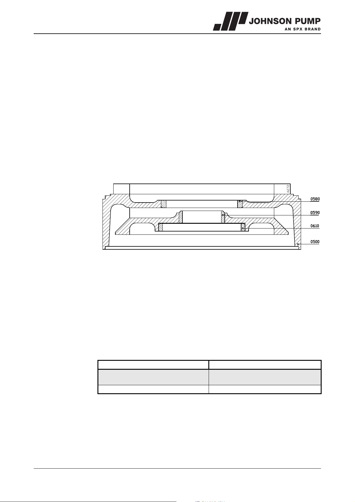
Use a suitable assembly bush for inserting the wear rings. The flat side of the wear rings
must be positioned equally with the flat side of the cover, see figure 8
Figure 8: Fitting the wear rings.
1 Fit the small wear rings (0590) into the covers (0510).
2 Fit a wear ring (0580) into the suction cover (0500).
3 Fit the wear rings (0580) and (0610) into the covers (0510).
4 Fit the wear rings (0610) into the pump cover (0530).
7.4.3 Pump assembly
1 Place a little Loctite 641 on the fitting face of the throttling bush (0070) and fit the
throttling bush into the pump casing (0020) for the drive side.
2 Fit the external circlip (0090) to the shaft (0570).
3 Fix the throttling sleeve (0600) to the shaft with a few drops of liquid locking agent.
The throttling sleeve is not used on all models, see below for a list:
Pump type Throttling sleeve used:
MCHZ(S) 12,5
MCHZ(S) 14a and 14b
MCHZ(S) 16 from 5 stages and higher
4 Push the pump shaft (0570) with the drive side from the inside out through the
pressure bracket (0020).
for 8 stages and higher
MCHZ/EN (0912) 4.2 Disassembly and assembly 31
Page 33
7.4.4 Assembling the stuffing box packing MCHZ
1 Fit the 5 packing rings. Place the packing rings with the openings offset. The packing
rings may only be bent open axially, see figure 7.
2 Fit the gland (0130). Tighten the nuts (0280) by hand.
3 Proceed with paragraph 7.4.6.
7.4.5 Assembling the mechanical seal MCHZS
! A mechanical seal is a vulnerable precision component. Leave the seal in the
original packaging until you start with the actual assembly. Ensure that the
working environment is dust free and that the parts and tools are clean.
Remove any paint from the components. Never place the slide rings on the
slide surfaces!
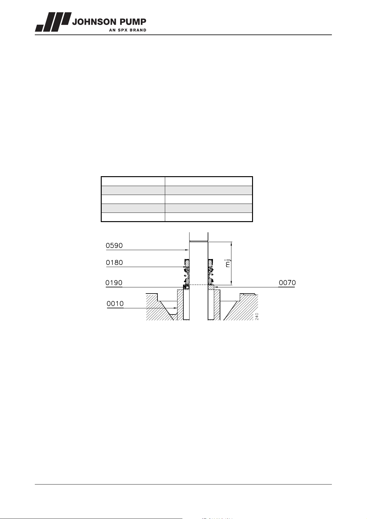
1 Fit the set ring (0060) and lock this with the adjustment screw (0280), see figure 9.
For the correct distance see the value mj in the table below:
Ty pe
MCHZS 12,5 x n - 3,2 49,5
MCHZS 14 a x n - 5 51
MCHZS 14 b x n - 5 51
MCHZS 16 x n - 6,5 56
mj (=drive side)
Figure 9: Distance mj.
2 Before fitting check whether the grooves for the external circlips (0220) have any
sharp edges.
3 Wet the clean shaft with some low-surface-tension water (add detergent) and feed
the bellows part of the seal (0140) with a slight twist in clockwise direction onto the
shaft. Apply pressure or tension during assembly via the rear end of the
spring only. The sliding surface must face towards the shaft end, drive side.
4 Wet the seal chamber with some low-surface-tension water (add detergent) and fit
the static ring of the mechanical seal (0140) into the seal cover (0050), with the
sliding surface pointing out.
5 Fit the gasket (0150) and fit the cover (0050) into the pressure bracket.
6 Proceed with paragraph 7.4.6.
32 Disassembly and assembly MCHZ/EN (0912) 4.2
Page 34
MCHZ
4755
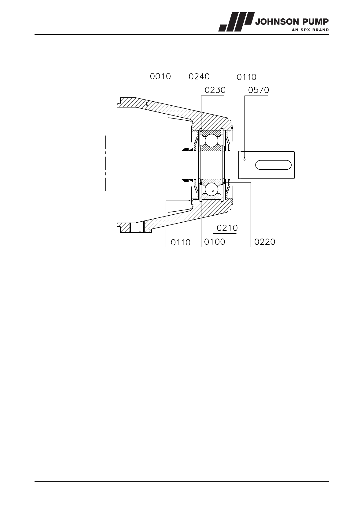
7.4.6 Assembling the bearing construction
Figure 10: Bearing construction.
See figure 10.
1 Fit the bearing cover (0100) to the inside of the bearing housing for the drive side,
this is the part which has the arrow for the direction of rotation.
2 Fit an internal circlip (0230) into the inner groove in the bearing housing.
3 Fix this bearing housing (0010) to the pressure bracket with the bolts (0290).
4 Fit the rubber V-ring (0240) over the pump shaft, with the narrow opening pointing to
the inside of the pump.
5 Fit the external circlip (0220) into the rear of the 2 grooves on the pump shaft and fit
the filling ring (0100).
6 Grease the bearing on both sides with ball bearing grease (not for 2RS-1 type
bearings!). For the correct type of grease see paragraph 10.6 "Post-greasing of ball
bearings".
7 Fit the bearing (0210) over the pump shaft and into the seat of the bearing housing
using a suitable assembly bush which rests on both the inner and outer rings of the
bearing.
8 Fit the other filling ring (0100) and external circlip (0220) to the pump shaft.
9 Fit the internal circlip (0230) into the bearing housing.
10 Fit the outermost bearing cover (0110) and the rubber V-ring (0240), with the narrow
opening pointing to the outside of the pump.
MCHZ/EN (0912) 4.2 Disassembly and assembly 33
Page 35
7.4.7 Assembling the stage set
1 Fit the sub-assembly which you have just assembled with the shaft vertically, drive
side down. Use a support for this with an opening to provide space for the shaft end.
2 Fit a gasket (0660) and place the suction cover (0030). This is pressed over the
throttling sleeve (0070).
3 Fit a key (0730) to the pump shaft and fit the air wheel (0040) to the shaft. Fit the
external circlip (0090) to the shaft.
4 Fit the gasket (0160) and fit the pump cover (0530). Make sure the gasket is in
the correct position!
5 Fit a key (0730) in the pump shaft and fit an impeller (0520), the inlet opening of the
impeller must point up.
6 Fit the gasket (0660) and fit a stage casing (0510) on the pressure bracket.
7 Repeat steps 5 and 6 until the last impeller has been fitted.
8 Secure the impeller set by fitting an external circlip (0090) to the pump shaft.
9 Fit a gasket (0660) and place the suction cover (0500) on the stage set.
10 Fit a gasket (0660) to the inlet casing using assembly grease. Place the inlet casing
(0020) over the shaft end on the stage set.
11 Fit the tie rods (0740) with the nuts (0750). For MCHZ(S) 12.5 x 1-3, MCHZ(S)
14a/b x 1-3 and MCHZ(S) 16 x 1: fit the bolts and nuts (0770).
12 For the remaining operations see paragraph 7.4.4. With the exception of the following
points:
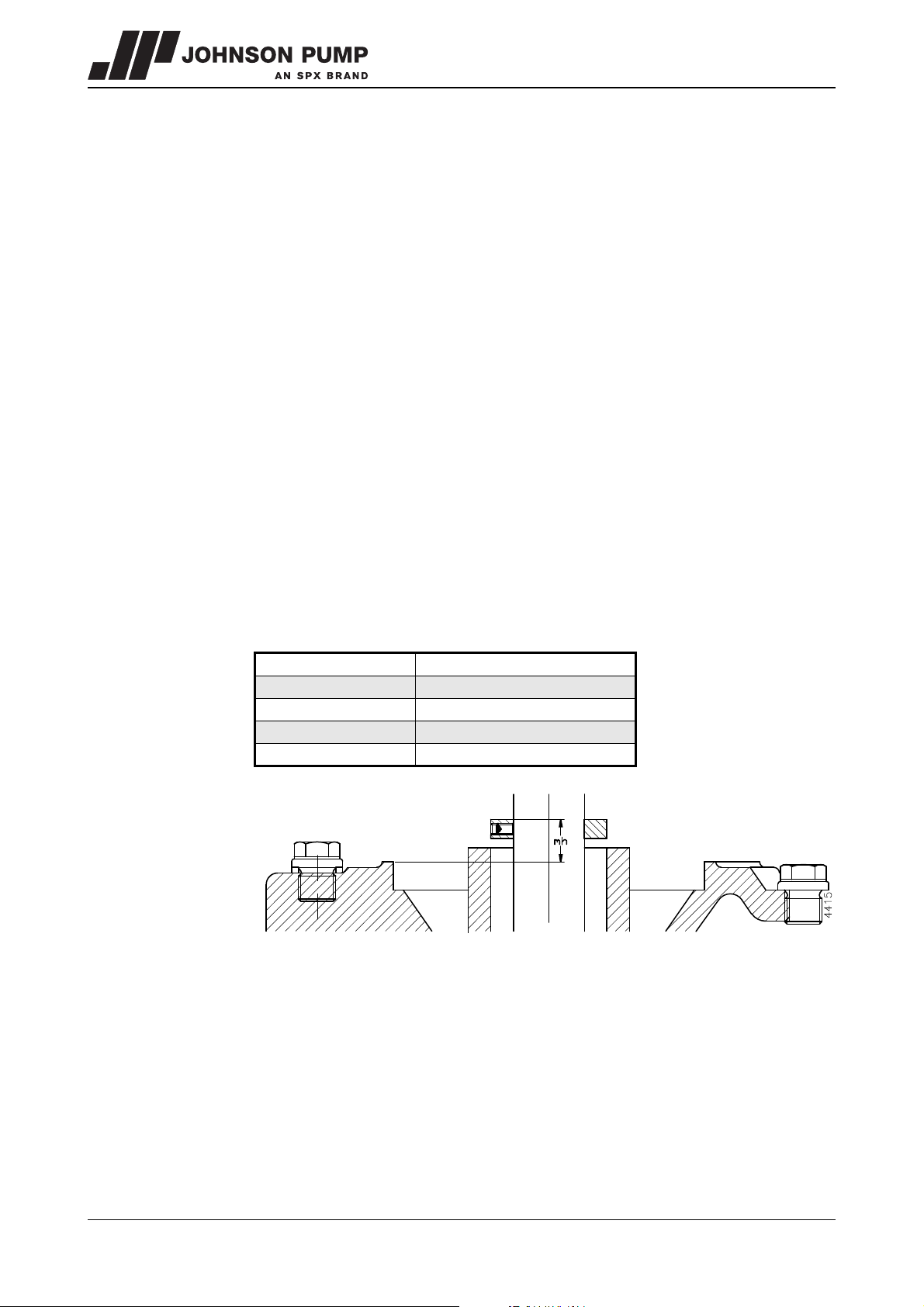
• The value mj from step 1 of paragraph 7.4.5 is replaced by the value mh, for which
the correct values are shown in the table below:
Pump type
MCHZS 12,5 x n - 3,2 20,2
MCHZS 14 a x n - 5 18,7
MCHZS 14 b x n - 5 18,7
MCHZS 16 x n - 6,5 14
mh (=non-drive side)
Figure 11: Distance mh.
• Steps 9 and 10 of paragraph 7.4.6 replaced by: Fit the closed bearing cover (0120)
13 Fit the by-pass pipe (0670) if present.
34 Disassembly and assembly MCHZ/EN (0912) 4.2
Page 36
MCHZ
7.5 Disassembling MCHZ(S) 14a/b heavy bearing construction
Make sure that the power supply to the pump is switched off and that no one can switch
the pump on again unintentionally!
If there is no illustration with the instruction, the item numbers used relate to the
illustrations in the parts list for this pump, in chapter 9.
7.5.1 Replacing the stuffing box packing MCHZ
If the pump has to be dismantled further then replacement of the packing rings will be
easier if the bearing housings (0020 and 0010) have been removed.
If only the packing rings have to be replaced then the pump does not need to be
disconnected from the pipe work and it can remain on the foundation. Proceed as
follows, this applies for both sides of the pump:
1 Remove the gland nuts (0280) and pull the gland (0140) backwards.
2 Remove the packing rings (0160) from the stuffing box. Use the special packing
puller for this, see figure 6.
3 Clean the stuffing box and then grease it with graphite grease or silicone grease. Also
grease the new packing rings.
4 Bend open the first packing ring as shown in figure 7 and fit it around the shaft.
Thoroughly press the ring home using a suitable piece of halved tube.
5 Fit the other rings. Press these well home one by one. Ensure that the cuts are at 90°
with regard to each other.
6 Press the gland against the last packing ring and tighten the gland nuts one by one by
hand.
7.5.2 Replacing the mechanical seal MCHZS
If only a mechanical seal has to be replaced the pump will have to be disassembled first.
Then the relevant bearing housing will have to be removed. For this see paragraph 7.5.5
and paragraph 7.5.9. Then see paragraph 7.5.6 for disassembly of the mechanical seal.
7.5.3 Disassembling the pump
1 Uncouple the inlet and outlet pipes. Make sure that they are sufficiently supported.
2 Slacken the foundation bolts and remove the pump from the pipe work.
7.5.4 Disassembling the bearing housing on the drive side
1 Uncouple the coupling halve from the pump shaft (0570) and remove the key (0200).
2 Only for MCHZS: Slacken the balance pipe (0670).
3 Place the pump vertically in a support, with the shaft end up.
4 Remove the rubber V-ring (0250) and the bearing cover (0080).
5 Slide the inner rubber V-ring over the shaft and slacken the inner bearing cover
(0120). This is now free from the pump shaft.
6 Remove the outer external circlip (0230) and the filling ring (0110) from the pump
shaft.
7 Slacken the bolts (0300) and pull the bearing housing (0020) vertically from the
pump section. The bearings will be pulled from the pump shaft.
8 Remove the lower external circlip (0230) and the filling ring (0110) from the pump
shaft.
9 Remove the bearing cover and the rubber V-ring from the pump shaft.
10 Only for MCHZ: Disassemble the gland (0140) and remove the packing rings (0160).
MCHZ/EN (0912) 4.2 Disassembly and assembly 35
Page 37
7.5.5 Disassembling the ball bearings
1 Remove both internal circlips (0240) from the bearing bracket.
2 Using a suitable bush, resting on the outer ring of the bearing, press the bearings out
of the bearing bracket.
7.5.6 Disassembling the mechanical seal MCHZS
1 Remove the seal cover (0090) from the pump shaft and remove the static ring from
the mechanical seal.
2 Slide the rotating ring for the mechanical seal (0160) off the pump shaft.
If the reason for disassembly was to replace the mechanical seal, the new mechanical
seal can now be fitted. See from paragraph 7.6.5 for this.
7.5.7 Disassembling the set of stage casings
1 Uncouple the balance pipe (0670) if fitted.
2 Only for MCHZS: Slacken the adjustment screw (0330) and remove the set ring
(0190).
3 Unscrew the nuts (0750) from the tie rods (0740).
4 Remove the pump casing (0030) from the stage set. Using a suitable bush, press or
tap the throttling bush (0060) out of the inlet casing.
5 Remove the external circlip (0100) and any throttling sleeve (0600) from the pump
shaft.
6 Remove the end cover (0040) and the air wheel (0050). Remove the key (0730) from
the shaft and remove the gasket (0180).
7 Remove the pump cover (0530) and remove the external circlip (0090).
8 Remove all impellers (0520), stage casings (0510) and keys (0730).
9 Remove the suction cover (0500) from the pump casing (0030).
7.5.8 Disassembling the bearing housing on the suction side
1 Position the pump casing with the shaft horizontally.
2 Remove the rear bearing cover (0130).
3 Continue from step 5 of paragraph 7.5.4.
7.5.9 Disassembling the ball bearing on the suction side
See paragraph 7.5.5, with the exception of step 1.
7.5.10 Disassembling the mechanical seal on the MCHZS suction side
See paragraph 7.5.6, for which item no. (0160) now becomes: item no. (0150).
36 Disassembly and assembly MCHZ/EN (0912) 4.2
Page 38
MCHZ
7.6 Assembling the MCHZ(S)14a/b heavy bearing construction
7.6.1 Preparation for assembly
For the correct torque settings see paragraph 10.4 "Tightening moments for bolts and
nuts" and paragraph 10.5 "Tie rod torque".
For the correct lubricants and locking agents see paragraph 10.6 "Post-greasing of ball
bearings" and paragraph 10.7 "Recommended locking liquids".
! For assembly all relevant parts should always be clean and undamaged. Leave
bearings and seals for as long as possible in the packaging. If the bearing
does not need to be replaced the bearing and the bearing housing will have to
be cleaned and provided with new grease. The bearing at the non-drive end is
a 2RS1 type bearing and does not require any maintenance.
7.6.2 Sub-assembly of stage casings
Use a suitable assembly bush for inserting the wear rings. The flat side of the wear rings
must be positioned equally with the flat side of the cover, see figure 8.
Steps 2 and 3 are only applicable for design Q (= with bronze impellers)
1 Fit the small wear rings (0590) into the covers (0510).
2 Fit a wear ring (0580) into the suction cover (0500).
3 Fit the wear rings (0580) and (0610) into the covers (0510).
4 Fit the wear rings (0610) into the pump cover (0530).
7.6.3 Pump assembly
1 Place a little Loctite 641 on the fitting face of the throttling bush (0060) and fit the
throttling bush into the pump casing (0030) for the drive side.
2 Fit the external circlip (0100) to the shaft (0570).
3 Fix the throttling sleeve (0600) to the shaft with a few drops of liquid locking agent.
This throttling sleeve is used from 8 stages and higher.
4 Push the pump shaft (0570) with the drive side from the inside out through the
pressure bracket (0030).
7.6.4 Assembling the stuffing box packing MCHZ
Figure 12: Bending open a stuffing box packing ring.
1 Fit the 5 packing rings. Place the packing rings with the openings offset. The packing
rings may only be bent open axially, see figure 12.
2 Fit the gland (0140). Tighten the nuts (0290) by hand.
3 Proceed with paragraph 7.6.6.
MCHZ/EN (0912) 4.2 Disassembly and assembly 37
Page 39
7.6.5 Assembling the mechanical seal MCHZS
! A mechanical seal is a vulnerable precision component. Leave the seal in the
original packaging until you start with the actual assembly. Ensure that the
working environment is dust free and that the parts and tools are clean.
Remove any paint from the components. Never place the slide rings on the
slide surfaces!
1 Fit the set ring (0190) and lock this with the adjustment screw (0330).
The distance mj from the top of the set ring to the bottom of the external circlip
groove must be 54 mm.
2 Before fitting check whether the grooves for the external circlips (0220) have any
sharp edges.
3 Wet the clean shaft with some low-surface-tension water (add detergent) and feed
the bellows part of the seal (0160) with a slight twist in clockwise direction onto the
shaft. Apply pressure or tension during assembly via the rear end of the
spring only. The sliding surface must face towards the shaft end, drive side.
4 Wet the seal chamber with some low-surface-tension water (add detergent) and fit
the static ring of the mechanical seal (0160) into the seal cover (0090), with the
sliding surface pointing out.
5 Fit the gasket (0140) and fit the cover (0090) into the pressure bracket.
6 Proceed with paragraph 7.6.6.
38 Disassembly and assembly MCHZ/EN (0912) 4.2
Page 40
MCHZ
7.6.6 Assembling the bearing construction on the drive side
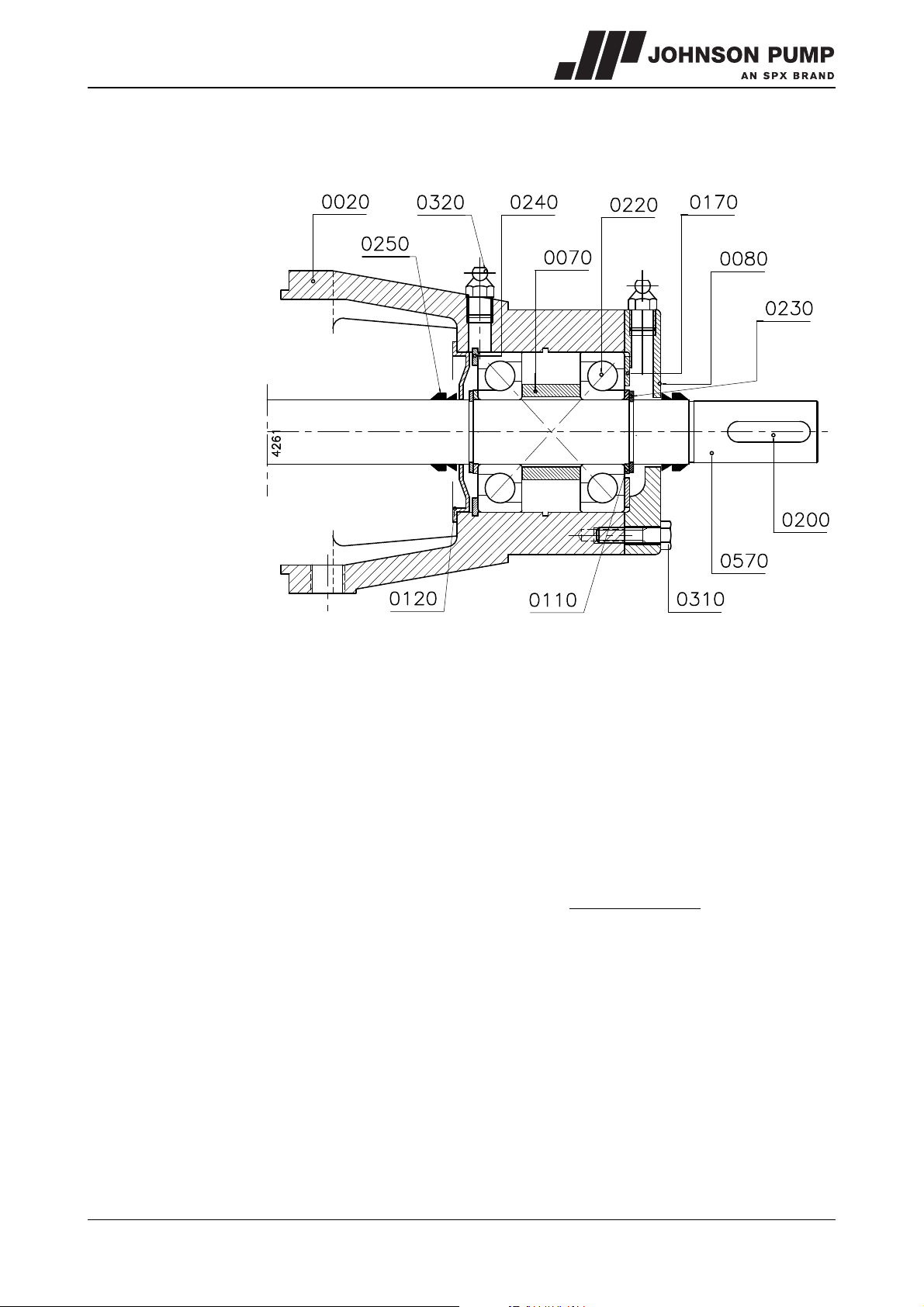
Figure 13: Assembly of the reinforced bearing construction.
See figure 13.
1 Fit the rubber V-ring (0250) over the pump shaft on the drive side, with the narrow
opening pointing to the inside of the pump.
2 Fit an internal circlip (0240) into the inner groove in the long bearing housing (0020)
and fit the bearing cover (0120) to the inside of this bearing housing.
3 Fix the bearing housing (0020) to the pressure bracket with the bolts (0300).
4 Fit the external circlip (0230) into the inner of the 2 grooves on the pump shaft on the
drive side and then fit the filling ring (0110).
5 Grease the bearings on both sides with ball bearing grease. For the correct type of
grease see paragraph 10.6 "Post-greasing of ball bearings".
! Attention: Both bearings have to be fitted in X-arrangement. This means that
both bearings have to be turned with the largest diameters facing each other.
6 Fit the first of the two bearings (0220) over the pump shaft and into the seat of the
bearing housing using a suitable assembly bush which rests on both the inner and
outer rings of the bearing.
7 Fit the spacer sleeve (0070) and fit the second of the two bearings (0220).
8 Fit the other filling ring (0110) and external circlip (0230) to the pump shaft.
9 Fit the waved ring (0170) into the bearing housing.
10 Fit the outer bearing cover (0080) with bolts (0310). Fit the rubber V-ring (0240),
with the narrow opening pointing to the outside of the pump.
MCHZ/EN (0912) 4.2 Disassembly and assembly 39
Page 41
7.6.7 Assembling the stage set
1 Fit the sub-assembly which you have just assembled with the shaft vertically, drive
side down. Use a support for this with an opening to provide space for the shaft end.
2 Fit a gasket (0660) and place the suction cover (0040). This is pressed over the
throttling sleeve (0060).
3 Fit a key (0730) to the pump shaft and fit the air wheel (0050) to the shaft. Fit the
external circlip (0100) to the shaft.
4 Fit the gasket (0180) and fit the pump cover (0530). Make sure the gasket is in
the correct position!
5 Fit a key (0730) in the pump shaft and fit an impeller (0520), the inlet opening of the
impeller must point up.
6 Fit the gasket (0660) and fit a stage casing (0510) on the pressure bracket.
7 Repeat steps 5 and 6 until the last impeller has been fitted.
8 Secure the impeller set by fitting an external circlip (0100) to the pump shaft.
9 Fit a gasket (0660) and place the suction cover (0500) on the stage set.
10 Fit a gasket (0660) to the inlet casing using assembly grease. Place the inlet casing
(0030) over the shaft end on the stage set.
11 Fit the tie rods (0740) with the nuts (0750).
12 For assembly of the other seal see paragraph 7.6.4 to paragraph 7.6.5. With the
exception of the following point:
• The value mj from step 1 of paragraph 7.6.5 now becomes 18,7.
7.6.8 Assembling the bearing construction on the suction side
1 Fit the rubber V-ring (0250) over the pump shaft, with the narrow opening pointing to
the inside of the pump.
2 Fit the bearing cover (0120) to the inside of the small bearing housing (0010).
3 Fix the bearing housing (0010) to the pressure bracket with the bolts (0300).
4 Fit the external circlip (0230) into the inner of the 2 grooves on the pump shaft and fit
a filling ring (0110).
5 Fit the bearing (0210) using a suitable mounting bush which rests on both the inner
and outer rings of the bearing.
6 Fit the second filling ring (0110) and fit the external circlip (0230) onto the pump
shaft.
7 Fit the outer bearing cover (0130).
8 Fit the by-pass pipe (0670) if present.
40 Disassembly and assembly MCHZ/EN (0912) 4.2
Page 42
MCHZ
7.7 Disassembling the MCHZ(S)20a/b
Make sure that the power supply to the pump is switched off and that no one
can switch the pump on again unintentionally!
If there is no illustration with the instruction, the item numbers used relate to the
illustrations in the parts list for this pump, in chapter 9.
7.7.1 Replacing the stuffing box packing MCHZ
If the pump has to be further dismantled then replacement of the packing rings will be
easier if the bearing housings (0010) are removed.
If only the packing rings have to be replaced then the pump does not need to be
disconnected from the pipe work and it can remain on the foundation.
Proceed as follows, this applies for both sides of the pump:
1 Remove the gland nuts (0350) and pull the gland (0170) backwards.
2 Remove the packing rings (0190) from the stuffing box. Use the special packing
puller for this, see figure 6.
3 Clean the stuffing box and then grease it with graphite grease or silicone grease. Also
grease the new packing rings.
4 Bend open the first packing ring as shown in figure 7 and fit it around the shaft.
Thoroughly press the ring home using a suitable piece of halved tube.
5 Fit the other rings. Press these well home one by one. Ensure that the cuts are at 90°
with regard to each other.
6 Press the gland against the last packing ring and tighten the gland nuts one by one by
hand.
7.7.2 Replacing the mechanical seal MCHZS
If only a mechanical seal has to be replaced the pump will have to be disassembled first.
Then the relevant bearing housing will have to be removed. For this see paragraph 7.3.4
and paragraph 7.3.8. Then see paragraph 7.3.6 for disassembly of the mechanical seal.
7.7.3 Disassembling the MCHZ(S)
1 Uncouple the inlet and outlet pipes. Make sure that they are sufficiently supported.
2 Slacken the foundation bolts and remove the pump from the pipe work.
7.7.4 Disassembling the bearing housing on the drive side
1 Uncouple the coupling halve from the pump shaft (0550) and remove the key (0260).
2 Only for MCHZS: Slacken the balance pipe (0620).
3 Place the pump vertically in a support, with the shaft end up.
4 Remove the rubber V-ring (0310) and the bearing cover (0140).
5 Slide the inner rubber V-ring over the shaft and slacken the inner bearing cover
(0140). This is now free from the pump shaft.
6 Remove the outer external circlip (0290) and the filling ring (0160) from the pump
shaft.
7 Slacken the bolts (0360) and pull the bearing housing (0010) vertically from the
pump section. The bearing will be pulled from the pump shaft.
8 Remove the lower external circlip (0290) and the filling ring (0160) from the pump
shaft.
9 Remove the bearing cover and the rubber V-ring from the pump shaft.
10 Only for MCHZ: Disassemble the gland (0170).
MCHZ/EN (0912) 4.2 Disassembly and assembly 41
Page 43
7.7.5 Disassembly of the ball bearing
1 Remove both internal circlips (0300) from the bearing bracket.
2 Using a suitable bush which rests on the outer ring of the bearing, press the bearing
(0280) out of the bearing bracket.
7.7.6 Disassembling the mechanical seal MCHZS
1 Remove the seal cover (0040) from the pump shaft and remove the static ring from
the mechanical seal.
2 Slide the rotating ring for the mechanical seal (0230) off the pump shaft.
If the reason for disassembly was to replace the mechanical seal, the new mechanical
seal can now be fitted. See from paragraph 7.8.5 for this.
7.7.7 Disassembling the set of stage casings
1 Uncouple the balance pipe (0650) if fitted.
2 Only for MCHZS: Slacken the adjustment screw (0400) and remove the set ring
(0120).
3 Unscrew the nuts (0690) from the tie rods (0670 and 0680).
4 Remove the pump casing (0020) from the stage set. Using a suitable bush press or
tap the throttling bush (0100) from the pump casing.
5 Remove the external circlip (0130) and any throttling sleeve (0110) from the pump
shaft.
6 Remove the end cover (0060) and remove the air-wheel (0070). Remove the key
(0660) from the shaft and remove the gasket (0210).
7 Remove the pump cover (0050) and remove the external circlip (0130).
8 Remove all impellers (0520), stage casings (0510) and keys (0660).
9 Remove the suction cover (0500) from the pump casing (0020) on the suction side.
7.7.8 Disassembling the bearing housing on the suction side
1 Position the pump casing with the shaft horizontally.
2 Remove the rear bearing cover (0150).
3 Continue from step 5 of paragraph 7.7.4.
7.7.9 Disassembling the ball bearing on the suction side
See paragraph 7.7.5, with exception of step 1, whereby item no. (0280) now becomes:
item no. (0270).
7.7.10 Disassembling the mechanical seal on the MCHZS suction side
See paragraph 7.7.6, whereby item no. (0230) becomes item no. (0220).
42 Disassembly and assembly MCHZ/EN (0912) 4.2
Page 44
MCHZ
7.8 Assembling the MCHZ(S) 20a/b
7.8.1 Preparation for assembly
For the correct torque settings see paragraph 10.4 "Tightening moments for bolts and
nuts" and paragraph 10.5 "Tie rod torque". For the correct lubricants and locking agents
see paragraph 10.6 "Post-greasing of ball bearings" and paragraph 10.7
"Recommended locking liquids".
! For assembly all relevant parts should always be clean and undamaged. Leave
bearings and seals for as long as possible in the packaging.
7.8.2 Sub-assembly of stage casings
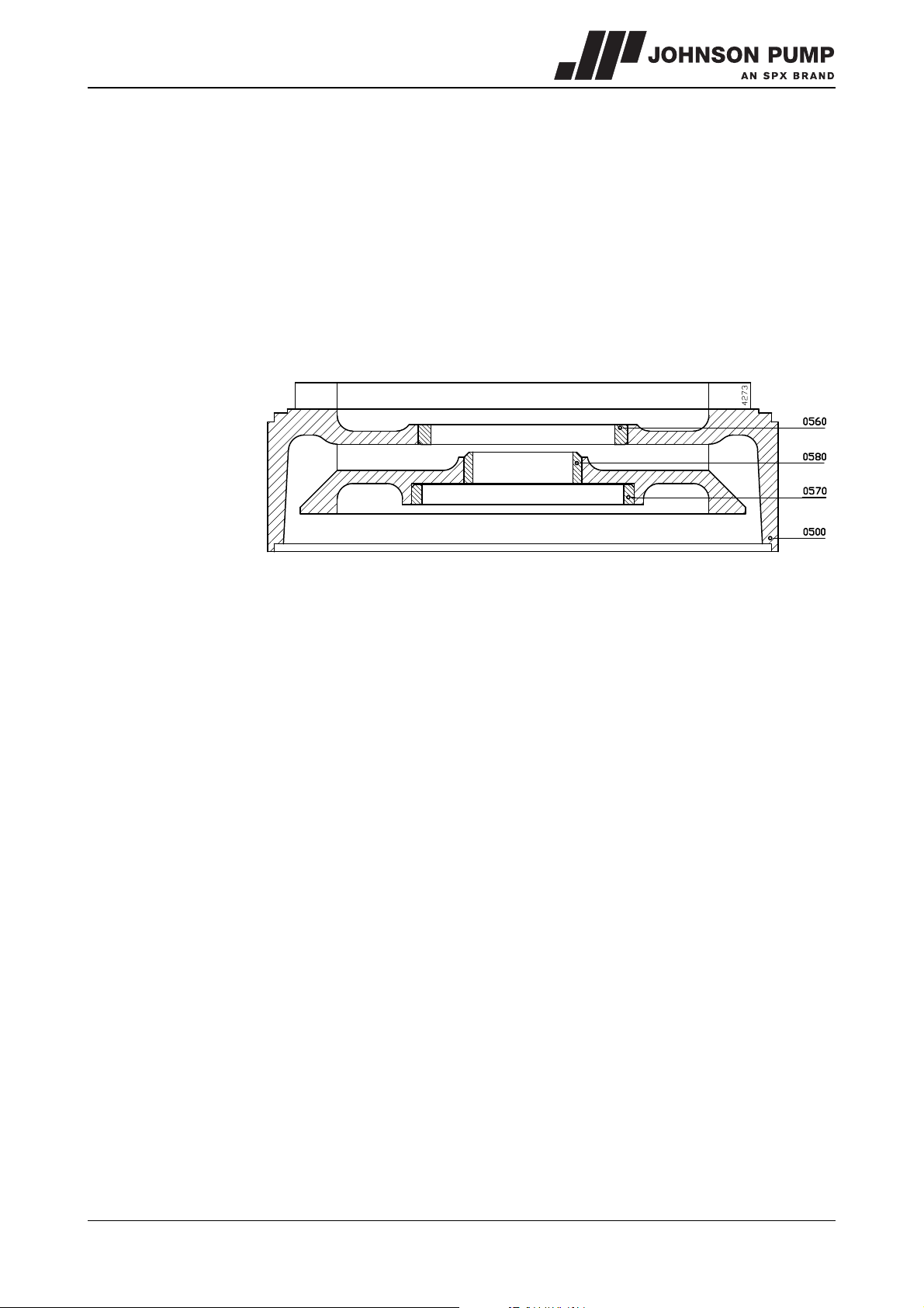
Figure 14: Fitting the wear rings
Use a suitable assembly bush for inserting the wear rings. The flat side of the wear rings
must be positioned equally with the flat side of the cover, see figure 14.
1 Fit the small wear rings (0580) into the covers (0510).
2 Fit a wear ring (0560) into the suction cover (0500).
3 Fit the wear rings (0560) and (0570) into the covers (0510).
4 Fit a wear ring (0570) into the pump cover (0050).
7.8.3 Pump assembly
1 Place a little Loctite 641 on the fitting face of the throttling bush (0100) and fit the
throttling bush into the pump casing (0020) for the drive side.
2 Fit the external circlip (0130) to the shaft (0550).
3 Fix the throttling sleeve (0110) to the shaft with a few drops of liquid locking agent.
4 Push the pump shaft (0550) with the drive side from the inside out through the
pressure bracket (0020).
MCHZ/EN (0912) 4.2 Disassembly and assembly 43
Page 45
7.8.4 Assembling the stuffing box packing MCHZ
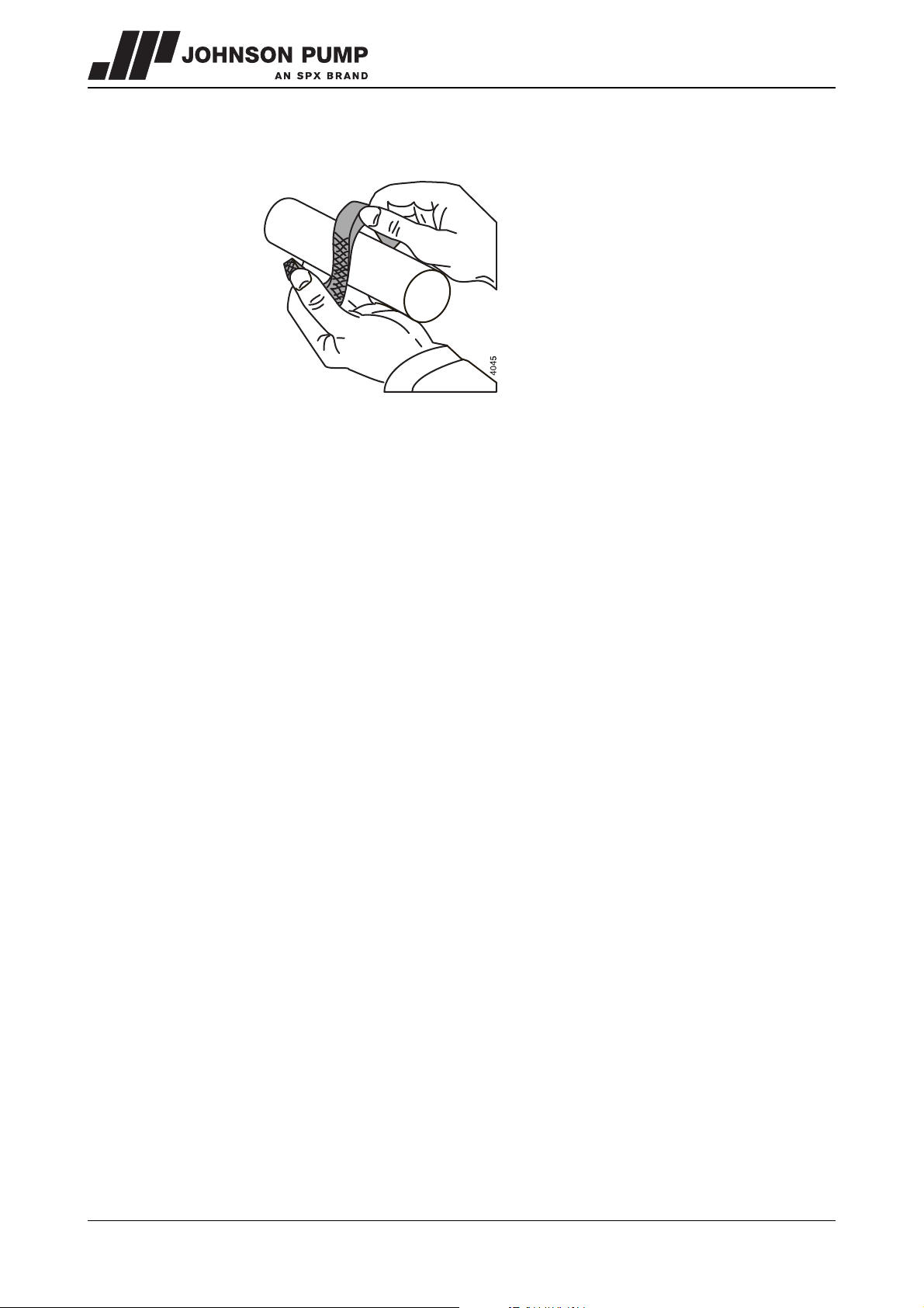
Figure 15: Bending open of gland packing rings.
1 Fit the 5 packing rings. Place the packing rings with the openings offset. The packing
rings may only be bent open axially, see figure 15.
2 Fit the gland (0170). Tighten the nuts (0350) by hand.
3 Proceed with paragraph 7.8.6.
7.8.5 Assembling the mechanical seal MCHZS
! A mechanical seal is a vulnerable precision component. Leave the seal in the
original packaging until you start with the actual assembly. Ensure that the
working environment is dust free and that the parts and tools are clean.
Remove any paint from the components. Never place the slide rings on the
slide surfaces and never touch the slide surfaces with ones fingers!
1 Fit the set ring (0120) and lock it with the adjustment screw (0400). The distance
between the set ring and the nearest external circlip groove must be 64,5 mm.
2 Before fitting check whether the grooves for the external circlips (0290) have any
sharp edges.
3 Wet the clean shaft with some low-surface-tension water (add detergent) and feed
the bellows part of the seal (0230) with a slight twist in clockwise direction onto the
shaft. Apply pressure or tension during assembly via the rear end of the
spring only. The sliding surface must face towards the shaft end, drive side.
4 Wet the seal chamber with some low-surface-tension water (add detergent) and fit
the static ring of the mechanical seal (0230) into the seal cover (0040), with the
sliding surface pointing out.
5 Fit the gasket (0200) and fit the cover (0040) into the pressure bracket.
6 Proceed with paragraph 7.8.6.
44 Disassembly and assembly MCHZ/EN (0912) 4.2
Page 46
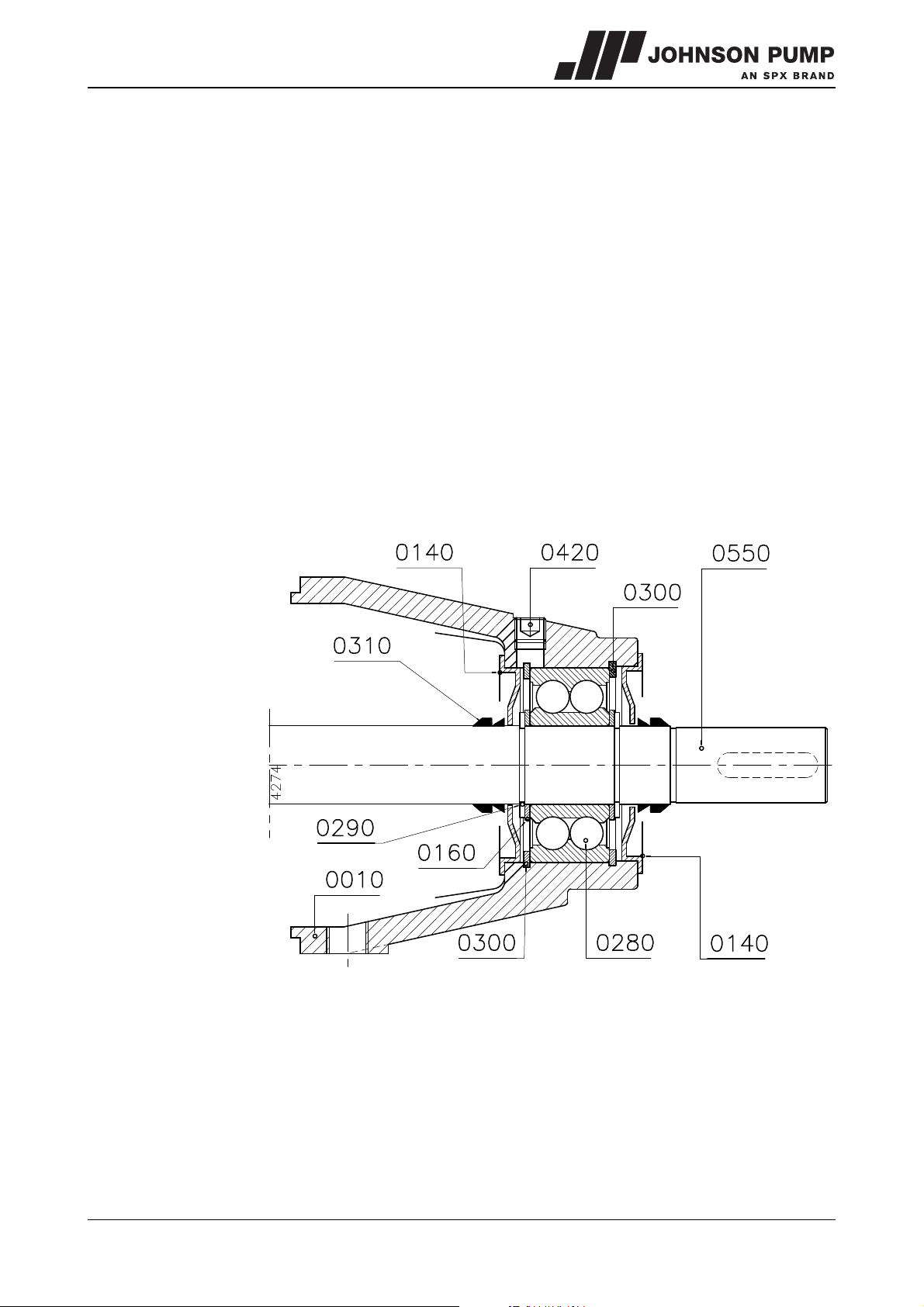
MCHZ
7.8.6 Assembling the bearing construction
See figure 16.
1 Fit the bearing cover (0140) to the inside of the bearing housing for the drive side,
this is the part which has the arrow for the direction of rotation.
2 Fit an internal circlip (0300) into the inner groove in the bearing housing.
3 Fix this bearing housing (0010) to the pressure bracket with the bolts (0360).
4 Fit the rubber V-ring (0310) over the pump shaft, with the narrow opening pointing to
the inside of the pump.
5 Fit the external circlip (0290) into the inner of the 2 grooves on the pump shaft and fit
the filling ring (0160).
6 Fit the bearing (0280) over the pump shaft and into the seat of the bearing housing
using a suitable assembly bush which rests on both the inner and outer rings of the
bearing.
7 Fit the other filling ring (0160) and external circlip (0290) to the pump shaft.
8 Fit the internal circlip (0300) into the bearing housing.
9 Fit the outermost bearing cover (0140) and the rubber V-ring (0310), with the narrow
opening pointing to the outside of the pump.
Figure 16: Assembly of the double row ball bearing.
MCHZ/EN (0912) 4.2 Disassembly and assembly 45
Page 47
7.8.7 Assembling the stage set
1 Fit the sub-assembly which you have just assembled with the shaft vertically, drive
side down. Use a support for this with an opening to provide space for the shaft end.
2 Fit a gasket (0600) and place the suction cover (0060). This is pressed over the
throttling sleeve (0100).
3 Fit a key (0660) to the pump shaft and fit the air wheel (0070) to the shaft. Fit the
external circlip (0130) to the shaft.
4 Fit the gasket (0600) and fit the pump cover (0050). Make sure the gasket is in
the correct position!
5 Fit a key (0660) in the pump shaft and fit an impeller (0520), the inlet opening of the
impeller must point up.
6 Fit the gasket (0600) and fit a stage casing (0510) on the pressure bracket.
7 Repeat steps 5 and 6 until the last impeller has been fitted.
8 Secure the impeller set by fitting an external circlip (0130) to the pump shaft.
9 Fit a gasket (0600) and place the suction cover (0500) on the stage set.
10 Fit a gasket (0600) into the inlet casing using assembly grease. Place the pump
casing suction side (0020) over the shaft end on the stage set.
11 Fit the tie rods (0670 and 0680) with the nuts (0690).
12 For the remaining operations see paragraph 7.8.4. With the exception of the following
points:
• The set ring must be fitted with a distance of 8 mm between the top of the set ring
and the edge of the stuffing box in the pump casing.
• Steps 9 and 10 of paragraph 7.8.6 replaced by: Fit the closed bearing cover (0150).
13 Fit the by-pass pipe (0650) if present.
46 Disassembly and assembly MCHZ/EN (0912) 4.2
Page 48
MCHZ
8Dimensions
MCHZ/EN (0912) 4.2 Dimensions 47
Page 49
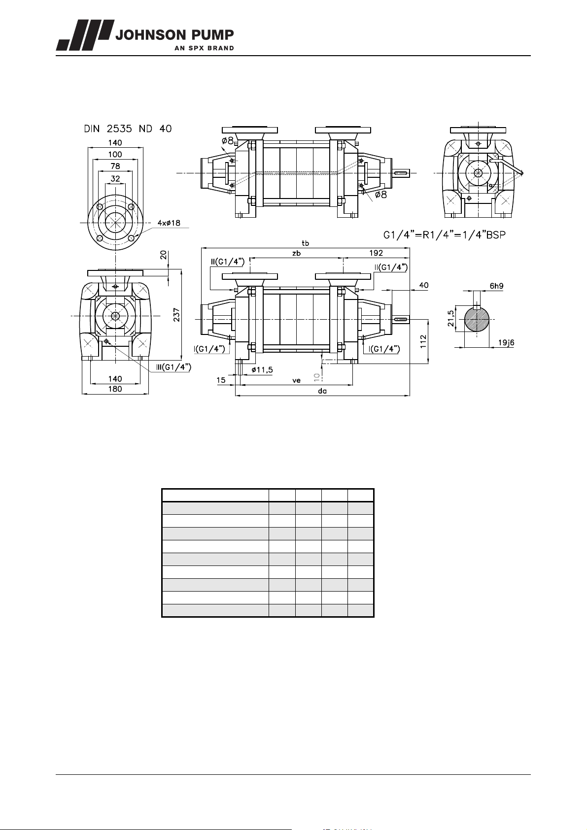
8.1 Dimensions MCHZ(S) 12,5
4516
MCHZS
Figure 17: Dimensions sketch MCHZ(S) 12,5.
I= leakage water drain
II= pressure gauge connection
III= drain plug
MCHZ - MCHZS da tb ve zb
12,5 x 1 405 507 227 169
12,5 x 2 450 552 272 214
12,5 x 3 495 597 317 259
12,5 x 4 540 642 362 304
12,5 x 5 585 687 407 349
12,5 x 6 630 732 452 394
12,5 x 7 675 777 497 439
12,5 x 8 720 822 542 484
12,5 x 9 765 867 587 529
48 Dimensions MCHZ/EN (0912) 4.2
Page 50
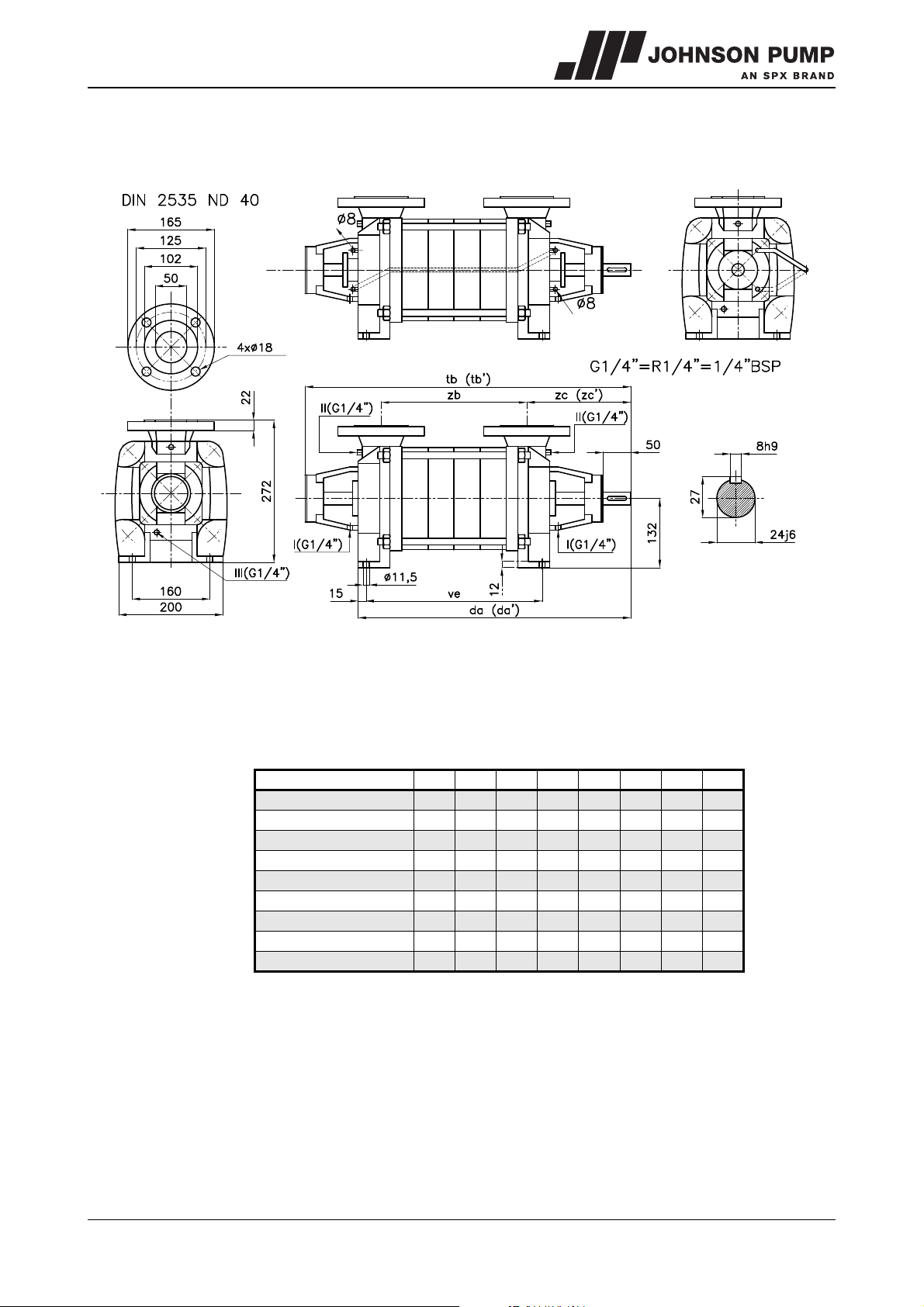
MCHZ
4517
MCHZS
8.2 Dimensions MCHZ(S) 14a/b
Figure 18: Dimensions sketch MCHZ(S) 14a/b.
I= leakage water drain
II= pressure gauge connection
III= drain plug
MCHZ - MCHZS da da' tb tb' ve zb zc zc'
14a/b x 1 425 527 237 179 202
14a/b x 2 475 577 287 229 202
14a/b x 3 525 627 337 279 202
14a/b x 4 575 677 387 329 202
14a/b x 5 625 671 727 773 437 379 202 248
14a/b x 6 675 721 777 823 487 429 202 248
14a/b x 7 771 873 537 479 248
14a/b x 8 821 923 587 529 248
14a/b x 9 871 973 637 579 248
da', tb' and zc' = Pump with heavy bearing construction
MCHZ/EN (0912) 4.2 Dimensions 49
Page 51
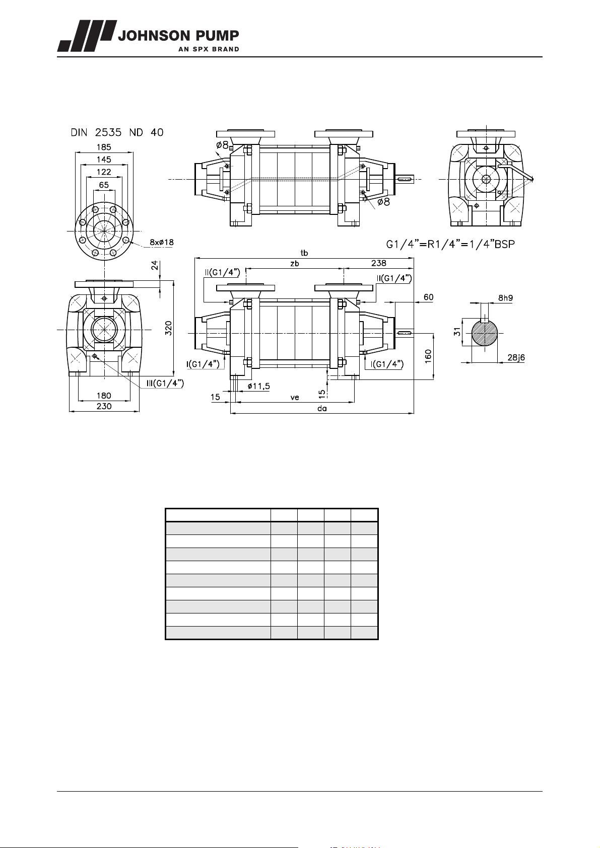
8.3 Dimensions MCHZ(S) 16
4518
MCHZS
Figure 19: Dimensions sketch MCHZ(S) 16.
I= leakage water drain
II= pressure gauge connection
III= drain plug
MCHZ - MCHZS da tb ve zb
16 x 1 - 6,5 495 624 267 217
16 x 2 - 6,5 555 684 327 277
16 x 3 - 6,5 615 744 387 337
16 x 4 - 6,5 675 804 447 397
16 x 5 - 6,5 735 864 507 457
16 x 6 - 6,5 795 924 567 517
16 x 7 - 6,5 955 984 627 577
16 x 8 - 6,5 915 1044 687 637
16 x 9 - 6,5 975 1104 747 697
50 Dimensions MCHZ/EN (0912) 4.2
Page 52
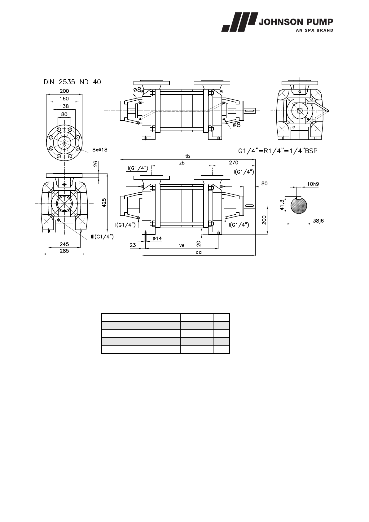
MCHZ
4519
MCHZS
8.4 Dimensions MCHZ(S) 20
Figure 20: Dimensions sketch MCHZ(S) 20a/b.
I= leakage water drain
II= pressure gauge connection
III= drain plug
MCHZ - MCHZS da tb ve zb
20a/b x 1 600 727 332 282
20a/b x 2 675 802 407 357
20a/b x 3 750 877 482 432
20a/b x 4 825 952 557 507
MCHZ/EN (0912) 4.2 Dimensions 51
Page 53
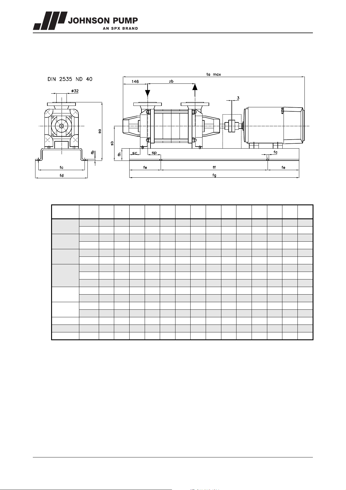
8.5 Dimensions of unit MCHZ(S) 12,5
Figure 21: Dimensions sketch unit MCHZ(S) 12,5.
MCHZ
MCHZS
12,5 x 1
12,5 x 2
12,5 x 3
12,5 x 4
12,5 x 5
12,5 x 6
12,5 x 7 132S 19 10 425 475 160 800 1120 70 307 202 0 44 1246 439
12,5 x 8 132S 19 10 425 475 160 800 1120 70 307 202 0 44 1291 484
12,5 x 9 132S 24 10 435 495 175 900 1250 70 307 202 0 44 1336 529
IEC
motor
90S 15 5 290 334 105 500 710 40 277 152 0 44 815 169
90L 15 5 290 334 105 500 710 40 277 152 0 44 840 169
90L 19 5 300 348 120 560 800 40 277 152 0 44 885 214
100L 19 5 300 348 120 560 800 40 277 152 0 44 930 214
100L 19 6 350 398 135 630 900 50 287 162 0 44 975 259
112M 19 6 350 398 135 630 900 50 287 162 0 44 995 259
100L 19 6 350 398 135 630 900 50 287 162 0 44 1020 304
112M 19 6 350 398 135 630 900 50 287 162 0 44 1040 304
132S 19 6 350 398 135 630 900 50 307 182 0 44 1111 304
112M 19 8 425 473 145 710 1000 63 300 175 0 44 1085 349
132S 19 8 425 473 145 710 1000 63 300 195 0 44 1156 349
112M 19 8 425 473 145 710 1000 63 300 175 0 44 1130 394
132S 19 8 425 473 145 710 1000 63 300 195 0 44 1201 394
fa fb fc fd fe ff fg fh sa sb sc sp ta
max
zb
52 Dimensions MCHZ/EN (0912) 4.2
Page 54
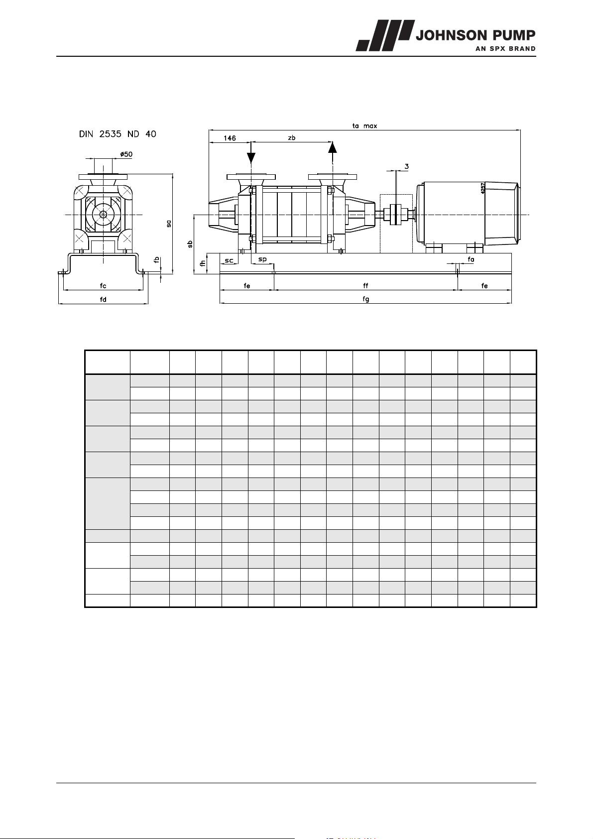
MCHZ
8.6 Dimensions of unit MCHZ(S) 14a
Figure 22: Dimensions sketch unit MCHZ(S) 14a/b.
MCHZ
MCHZS
14a x 1
14a x 2
14a x 3
14a x 4
14a x 5
14a x 6 160M 24 10 435 495 175 900 1250 70 370 230 0 44 1445 429
14a x 7
14a x 8
14a x 9 160M 24 10 435 495 200 1000 1400 80 380 240 0 44 1595 579
IEC
motor
100L 19 5 300 348 120 560 800 40 312 172 0 44 905 179
112M 19 5 300 348 120 560 800 40 312 172 0 44 925 179
112M 19 5 300 348 120 560 800 40 312 172 0 44 975 229
132S 19 6 350 398 135 630 900 50 322 182 0 44 1046 229
132S 19 6 350 398 135 630 900 50 322 182 0 44 1096 279
160M 19 8 425 473 145 710 1000 63 363 223 0 44 1249 279
132S 19 8 425 473 145 710 1000 63 335 195 0 44 1146 329
160M 19 8 425 473 145 710 1000 63 363 223 0 44 1299 329
132S 19 8 425 473 145 710 1000 63 335 195 0 44 1196 379
132S 19 10 425 475 160 800 1120 70 342 202 0 44 1242 379
160M 19 8 425 473 145 710 1000 63 363 223 0 44 1349 379
160M 24 10 435 495 175 900 1250 70 370 230 0 44 1395 379
160M 24 10 435 495 200 1000 1400 80 380 240 0 44 1495 479
160L 24 10 435 495 200 1000 1400 80 380 240 0 44 1539 479
160M 24 10 435 495 200 1000 1400 80 380 240 0 44 1545 529
160L 24 10 435 495 200 1000 1400 80 380 240 0 44 1589 529
fa fb fc fd fe ff fg fh sa sb sc sp ta
132S and 160M = Pump with heavy bearing construction
zb
max
MCHZ/EN (0912) 4.2 Dimensions 53
Page 55
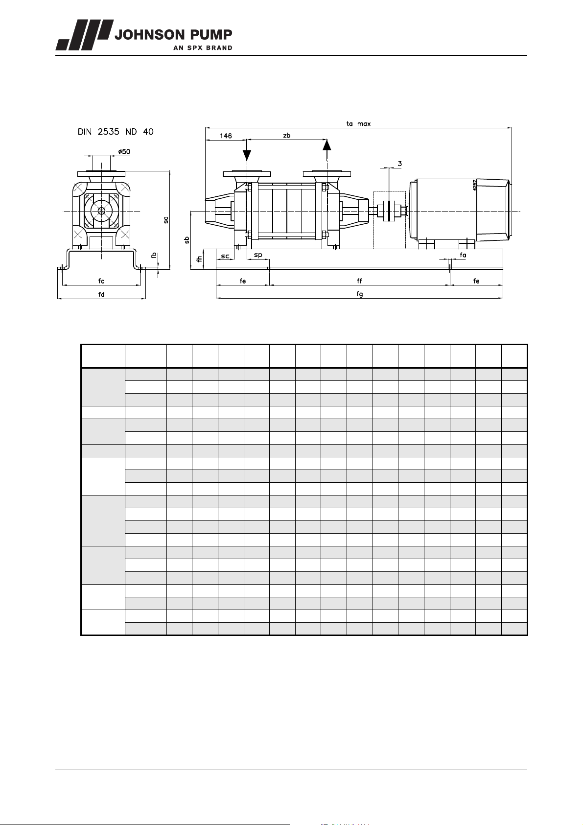
8.7 Dimensions of unit MCHZ(S) 14b
Figure 23: Dimensions sketch unit MCHZ(S) 14b.
MCHZ
MCHZS
14b x 1
14b x 2 132S 19 6 350 398 135 630 900 50 322 182 0 44 1046 229
14b x 3
14b x 4 132S 19 8 425 473 145 710 1000 63 335 195 0 44 1146 329
14b x 5
14b x 6
14b x 7
14b x 8
14b x 9
IEC
motor
100L 19 5 300 348 120 560 800 40 312 172 0 44 905 179
112M 19 5 300 348 120 560 800 40 312 172 0 44 925 179
132S 19 6 350 398 135 630 900 50 322 182 0 44 996 179
132S 19 6 350 398 135 630 900 50 322 182 0 44 1096 279
160M 19 8 425 473 145 710 1000 63 363 223 0 44 1249 279
160M 19 8 425 473 145 710 1000 63 363 223 0 44 1349 379
160M 24 10 435 495 175 900 1250 70 370 230 0 44 1395 379
160L 24 10 435 495 175 900 1250 70 370 230 0 44 1439 379
160M 24 10 435 495 175 900 1250 70 370 230 0 44 1445 429
160L 24 10 435 495 175 900 1250 70 370 230 0 44 1489 429
180M 24 10 485 545 175 900 1250 80 400 260 0 44 1460 429
180M 24 10 435 495 200 1000 1400 80 400 260 0 44 1506 429
160M 24 10 435 495 200 1000 1400 80 380 240 0 44 1495 479
160L 24 10 435 495 200 1000 1400 80 380 240 0 44 1539 479
180M 24 10 435 495 200 1000 1400 80 400 260 0 44 1556 479
160M 24 10 435 495 200 1000 1400 80 380 240 0 44 1545 529
180L 24 10 435 495 200 1000 1400 80 400 260 0 44 1606 529
160L 24 10 435 495 200 1000 1400 80 380 240 0 44 1595 579
180M 24 10 590 658 240 1120 1600 100 420 280 0 44 1656 579
fa fb fc fd fe ff fg fh sa sb sc sp ta
max
zb
160M and 180M = Pump with heavy bearing construction
54 Dimensions MCHZ/EN (0912) 4.2
Page 56
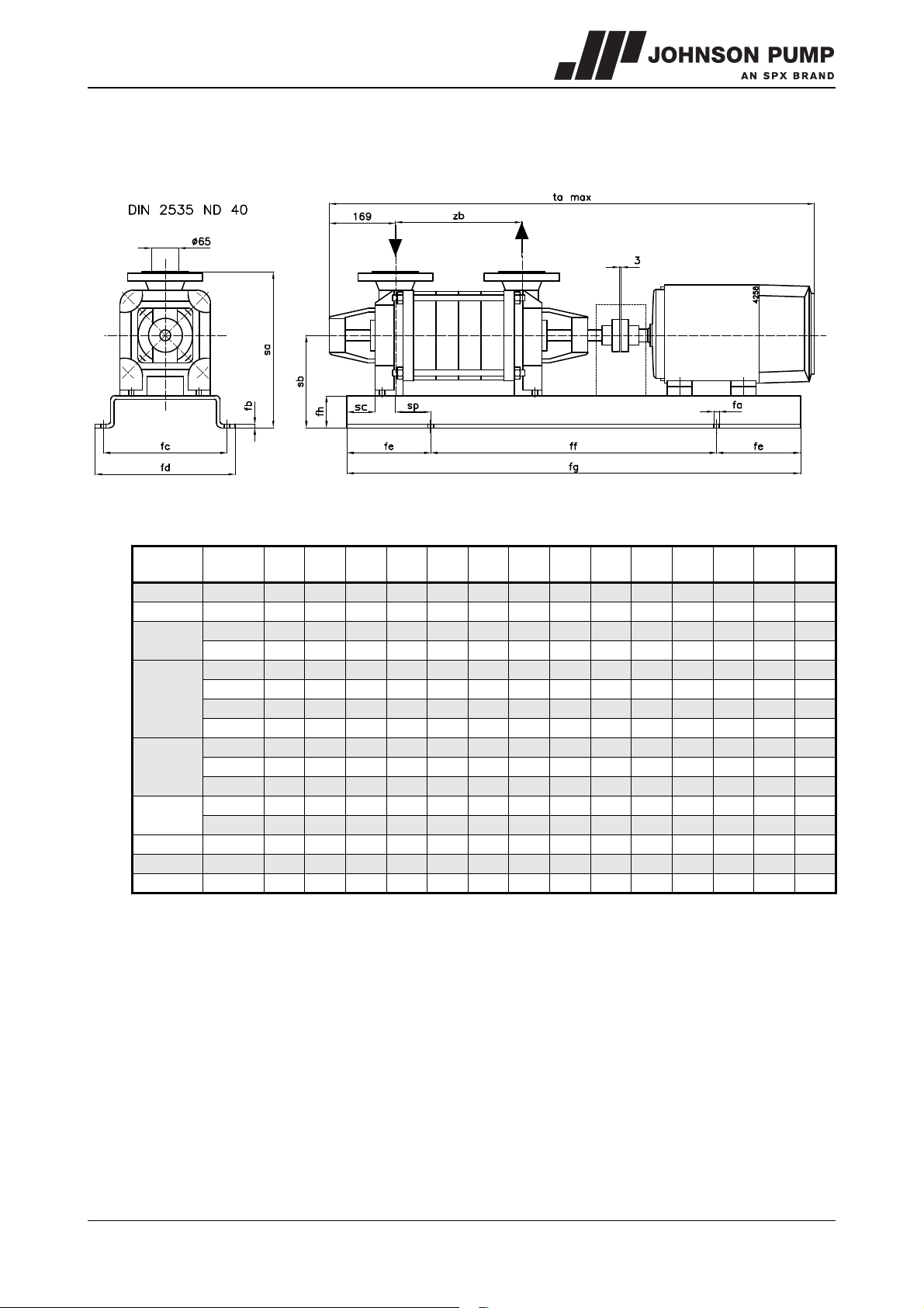
MCHZ
8.8 Dimensions of unit MCHZ(S) 16
Figure 24: Dimensions sketch unit MCHZ(S) 16.
MCHZ
MCHZS
16 x 1 132S 19 6 350 398 135 630 900 50 370 210 0 40 1093 217
16 x 2 160M 19 8 425 473 145 710 1000 63 383 223 0 40 1306 277
16 x 3
16 x 4
16 x 5
16 x 6
16 x 7 200L 24 10 590 658 240 1120 1600 100 420 300 0 40 1781 577
16 x 8 200L 24 10 590 658 240 1120 1600 100 420 300 0 40 1841 637
16 x 9 200L 24 10 590 658 240 1120 1600 100 420 300 0 40 1901 697
IEC
motor
160M 19 8 425 473 145 710 1000 63 383 223 0 40 1366 337
160L 24 10 435 495 175 900 1250 70 390 230 0 40 1410 337
160M 24 10 435 495 175 900 1250 70 390 230 0 40 1426 397
160L 24 10 435 495 175 900 1250 70 390 230 0 40 1470 397
180M 24 10 435 545 175 900 1250 80 400 260 0 40 1487 397
200L 24 10 535 595 200 1000 1400 90 410 290 0 40 1601 397
160L 24 10 435 495 200 1000 1400 80 400 240 0 40 1530 397
180M 24 10 435 495 200 1000 1400 80 400 260 0 40 1547 457
200L 24 10 535 595 200 1000 1400 90 410 290 0 40 1661 457
180M 24 10 435 495 200 1000 1400 80 400 260 0 40 1607 457
200L 24 10 590 658 240 1120 1600 100 420 300 0 40 1721 517
fa fb fc fd fe ff fg fh sa sb sc sp ta
max
zb
MCHZ/EN (0912) 4.2 Dimensions 55
Page 57
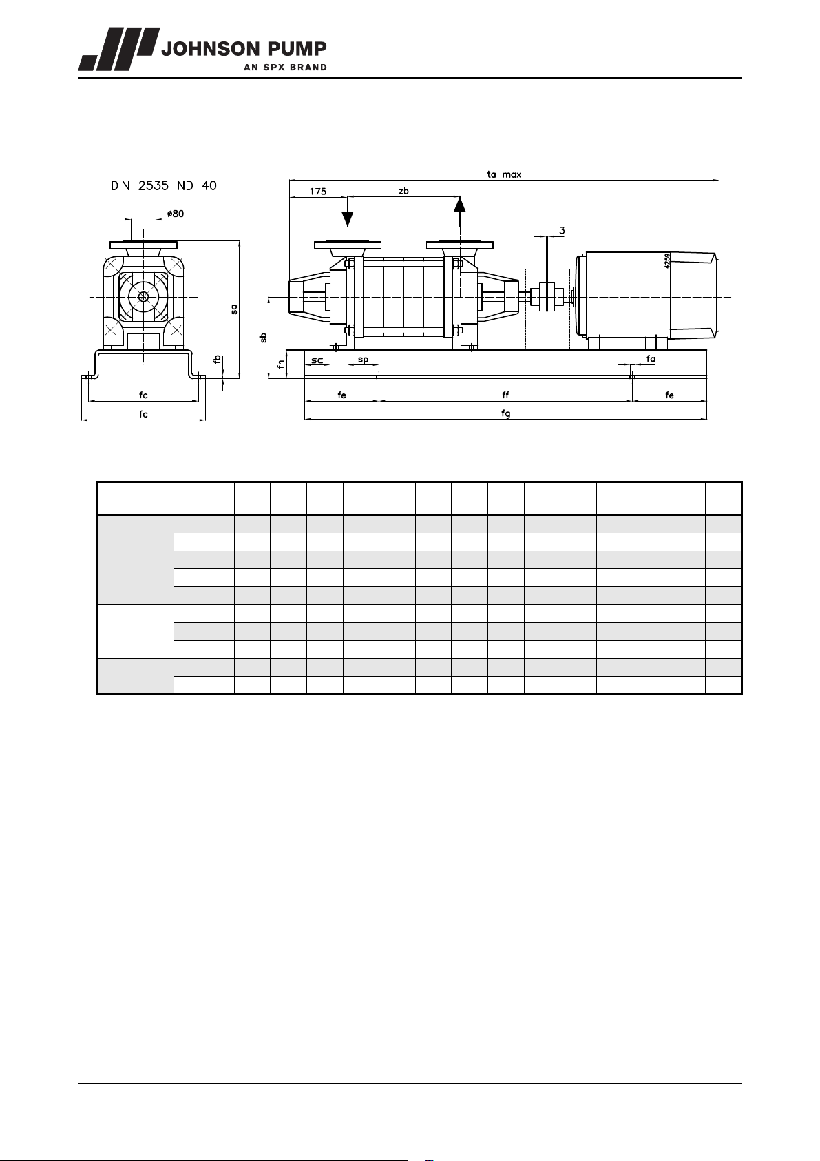
8.9 Dimensions of unit MCHZ(S) 20a
Figure 25: Dimensions sketch unit MCHZ(S) 20a.
MCHZ
MCHZS
20a x 1
20a x 2
20a x 3
20a x 4
IEC
motor
160M 19 8 425 473 145 710 1000 63 488 263 0 48 1349 282
160L 24 10 435 495 175 900 1250 70 495 270 0 48 1393 282
160L 24 10 435 495 175 900 1250 70 495 270 0 48 1468 357
180M 24 10 485 545 175 900 1250 80 505 280 0 48 1485 357
200L 24 10 535 595 200 1000 1400 90 515 290 0 48 1599 357
200L 24 10 535 595 200 1000 1400 90 515 290 0 48 1674 432
225M 24 10 590 658 240 1120 1600 100 550 325 0 48 1780 432
250M 24 10 720 788 240 1120 1600 130 605 380 0 48 1845 432
200L 24 10 590 658 240 1120 1600 100 525 300 0 48 1749 507
225M 24 10 590 658 240 1120 1600 100 550 325 0 48 1855 507
fa fb fc fd fe ff fg fh sa sb sc sp ta
max
zb
56 Dimensions MCHZ/EN (0912) 4.2
Page 58
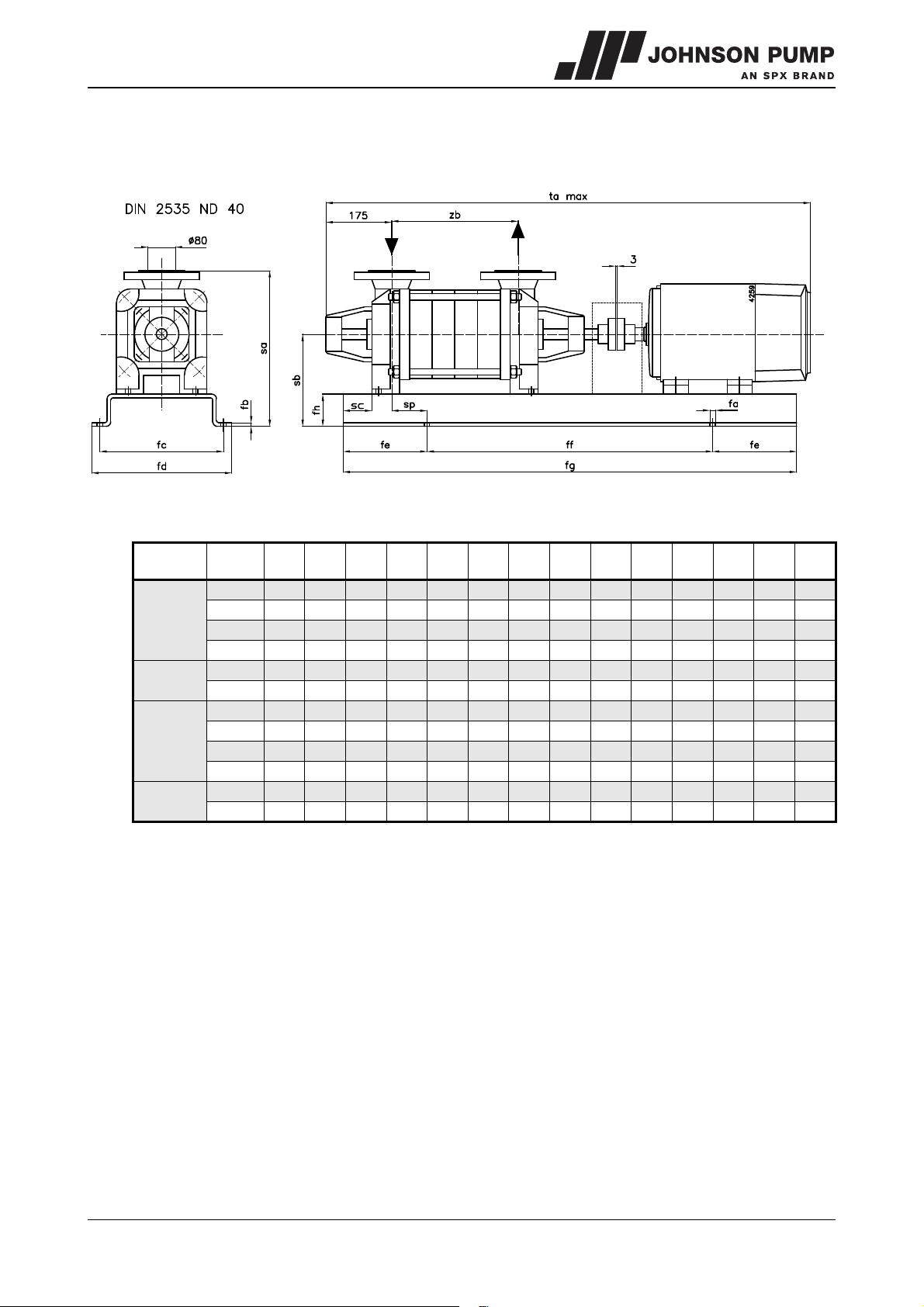
MCHZ
8.10 Dimensions of unit MCHZ(S) 20b
Figure 26: Dimensions sketch unit MCHZ(S) 20b.
MCHZ
MCHZS
20b x 1
20b x 2
20b x 3
20b x 4
IEC
motor
160L 19 8 425 473 145 710 1000 63 488 263 0 48 1349 282
160M 24 10 435 495 175 900 1250 70 495 270 0 48 1393 282
180M 24 10 485 545 175 900 1250 80 505 280 0 48 1410 282
200L 24 10 535 595 200 1000 1400 90 515 290 0 48 1524 282
200L 24 10 535 595 200 1000 1400 90 515 290 0 48 1599 357
225M 24 10 590 658 240 1120 1600 100 550 325 0 48 1705 357
200L 24 10 535 595 200 1000 1400 90 515 290 0 48 1674 432
225M 24 10 590 658 240 1120 1600 100 550 325 0 48 1780 432
250M 24 10 720 788 240 1120 1600 130 635 410 0 48 1845 432
280S 24 10 720 788 240 1120 1600 130 635 410 0 48 1900 432
225M 24 10 590 658 240 1120 1600 100 550 325 0 48 1855 507
280S 24 10 720 788 240 1120 1600 130 635 410 0 48 1975 507
fa fb fc fd fe ff fg fh sa sb sc sp ta
max
zb
MCHZ/EN (0912) 4.2 Dimensions 57
Page 59
58 Dimensions MCHZ/EN (0912) 4.2
Page 60
MCHZ
9Parts
9.1 Ordering parts
9.1.1 Order form
You can use the order form included in this manual for ordering parts.
When ordering parts always quote the following data:
1Your address.
2 The quantity, the item number and the description of the part.
3 The pump number. The pump number is stated on the label on the cover of this
manual and on the type plate of the pump.
4 In the event of different electric motor voltage you should state the correct voltage.
9.1.2 Recommended spare parts
Parts marked with a * are recommended spare parts.
9.2 Designs
The following designs are possible in the parts list below:
Cast iron:
• Design P: cast iron pump casings, stage casings and impellers
• Design Q: cast iron pump casings and stage casings, bronze impellers.
MCHZ/EN (0808) 4.1 Parts 59
Page 61
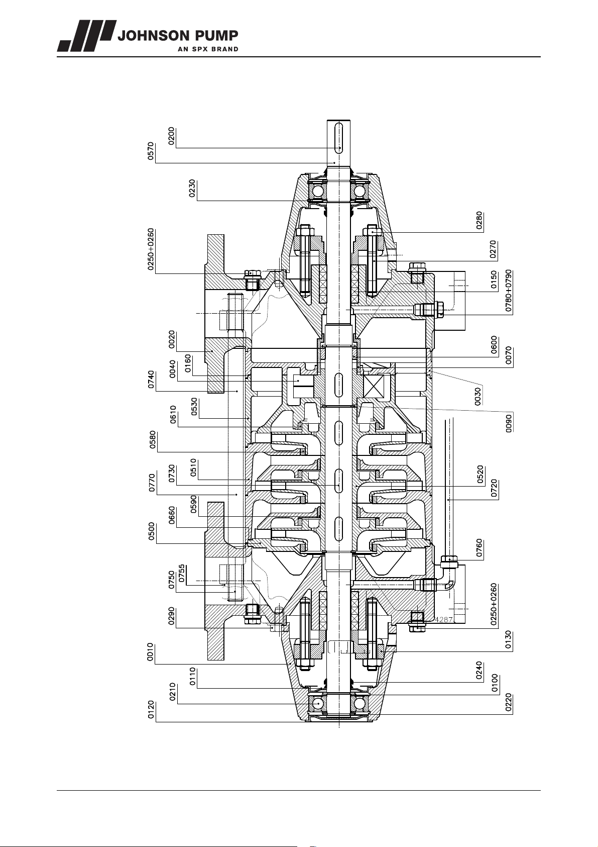
9.3 MCHZ 12,5 - 14a/b - 16
Figure 27: MCHZ 12,5 - 14a/b - 16.
60 Parts MCHZ/EN (0808) 4.1
Page 62
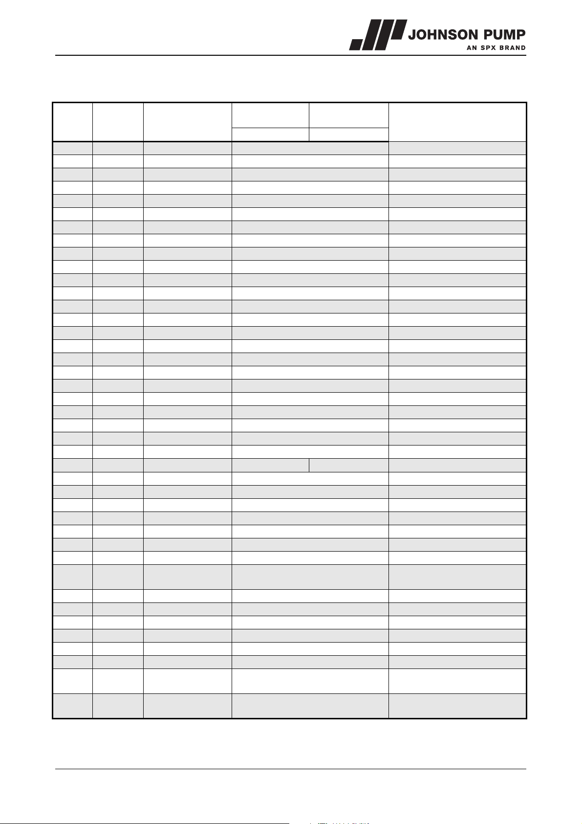
MCHZ
See figure 27
Item no Quantity Description
0010 2 bearing housing cast iron
0020 2 pump casing cast iron
0030 1 end cover cast iron
0040 1 air wheel aluminium bronze
0070* 1 throttling bush bronze
0090* 2 external circlip alloyed steel
0100* 4 filling ring steel
0110 3 bearing cover steel
0120 1 bearing cover steel
0130 2 gland cast iron
0150* 10 gland packing ring -0160* 1 gasket -0200* 1 key alloyed steel
0210* 2 ball bearing -0220* 4 external circlip steel
0230* 2 internal circlip steel
0240* 3 V-ring rubber
0250 4 plug steel
0260 4 sealing ring copper
0270 4 gland stud steel
0280 4 nut brass
0290 8 tap bolt steel
0500 1 suction cover cast iron
0510 n-1 stage casing cast iron
0520* n impeller cast iron
0530 1 pump casing cast iron
0570* 1 shaft alloyed steel
0580* n wear ring bronze
0590* n-1 wear ring bronze
0600 1 throttling ring alloyed steel only for MCHZ 12,5 x 8-9 and MCHZ 16 x 5-9
0610* n wear ring bronze
0660* n+3 gasket --
0720 1 balance pipe copper
0730* n+1 key alloyed steel
0740 4 tie rod alloyed steel not for MCHZ 12,5 x 1-3 and MCHZ 16 x 1
0750 8 nut steel not for MCHZ 12,5 x 1-3 and MCHZ 16 x 1
0755 4 washer stainless steel
0760 2 angle pipe union brass
0770 4 bolt with nut steel only for MCHZ12,5 x 1-3 and MCHZ 16 x 1
0780 2 plug steel
0790 2 sealing ring copper
Cast iron
Design P Design Q
Cast iron +
bronze impeller
bronze
Remarks
only for MCHZ 12,5 x 5-9, MCHZ 14a/b x 4-6
and MCHZ 16 x 3-9
only for MCHZ12,5 x 1-4, MCHZ 14a/b x 1-3
and MCHZ16 x 1-2
only for MCHZ 12,5 x 1-4, MCHZ 14a/b x 1-3
and MCHZ 16 x 1-2
MCHZ/EN (0808) 4.1 Parts 61
Page 63
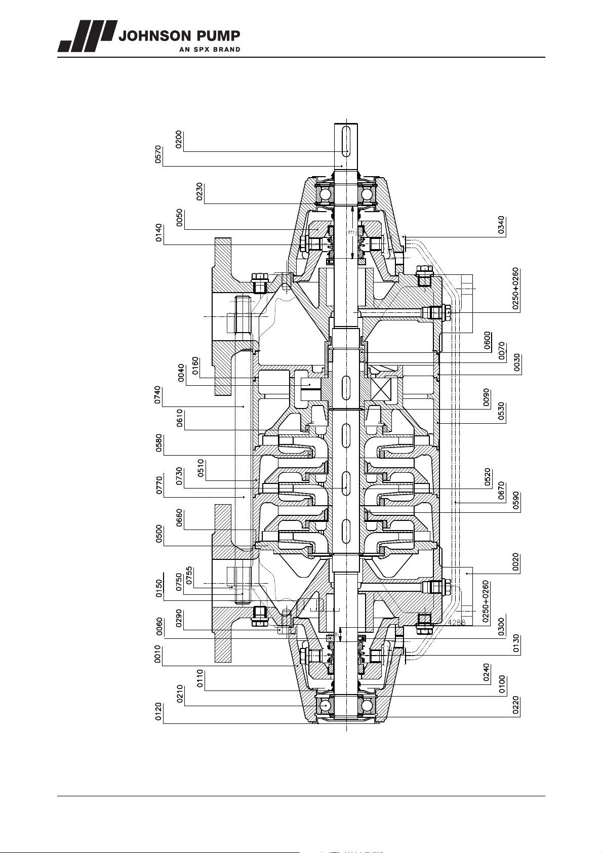
9.4 MCHZS 12,5 - 14a/b - 16
Figure 28: MCHZS 12,5 - 14a/b - 16.
62 Parts MCHZ/EN (0808) 4.1
Page 64
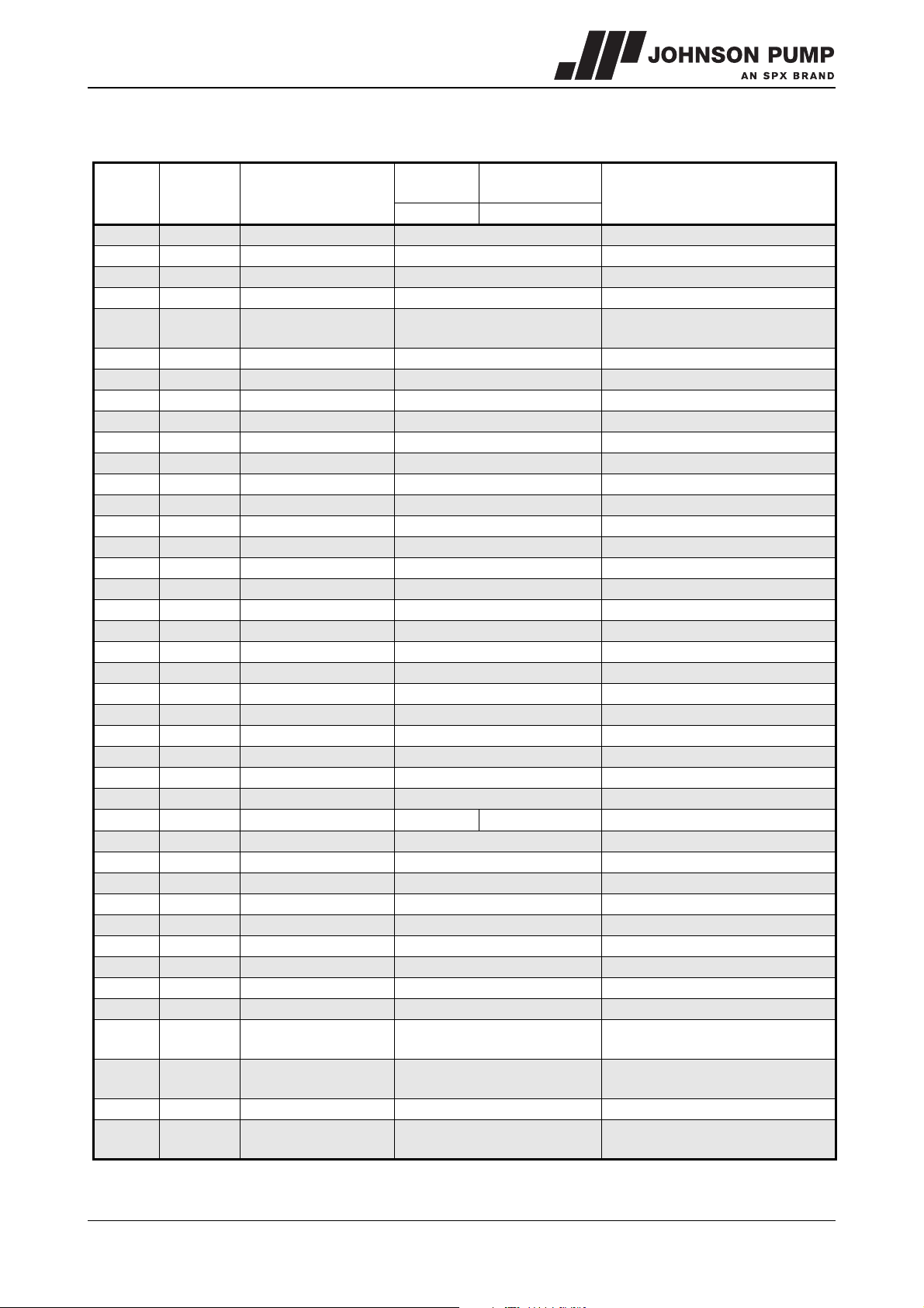
MCHZ
See figure 28.
Item no. Quantity Description
0010 2 bearing housing cast iron
0020 2 pump casing cast iron
0030 1 end cover cast iron
0040* 1 air wheel aluminium bronze
0050 2
0060* 2 set ring alloyed steel
0070* 1 throttling bush bronze
0090* 2 external circlip alloyed steel
0100* 4 filling ring steel
0110 3 bearing cover steel
0120 1 bearing cover steel
0130* 1 mechanical seal -0140* 1 mechanical seal -0150* 2 gasket -0160* 1 gasket -0200* 1 key alloyed steel
0210* 2 ball bearing -0220* 4 external circlip steel
0230* 2 internal circlip steel
0240* 3 V-ring rubber
0250 8 plug copper
0260 8 sealing ring copper
0290 8 tap bolt steel
0300 2 adjustment screw alloyed steel
0340 2 pipe union brass
0500 1 suction cover cast iron
0510 n-1 stage casing cast iron
0520* n impeller cast iron
0530 1 pump casing cast iron
0570* 1 shaft alloyed steel
0580* n wear ring bronze
0590* n-1 wear ring bronze
0600* 1 throttling sleeve alloyed steel only for MCHZS 12,5 x 8-9 and MCHZS 16 x 5-9
0610* n wear ring bronze
0660* n+3 gasket -0670* 1 balance pipe copper
0730 n+1 key alloyed steel
0740 4 tie rod alloyed steel
0750 8 nut steel
0755 4 washer stainless steel
0770 4 bolt with nut steel
cover for mechanical
seal
Cast iron
Design P Design Q
Cast iron +
bronze impeller
cast iron
bronze
Remarks
only for MCHZS 12,5 x 4-9 MCHZS 14a/b x 4-9,
MCHZS 16 x 2-9
only for MCHZS 12,5 x 4-9, MCHZS 14a/b x 4-9,
MCHZS 16 x 2-9
only for MCHZS 12,5 x 1-3, MCHZS 14a/b x 1-3,
MCHZS 16 x 1
MCHZ/EN (0808) 4.1 Parts 63
Page 65
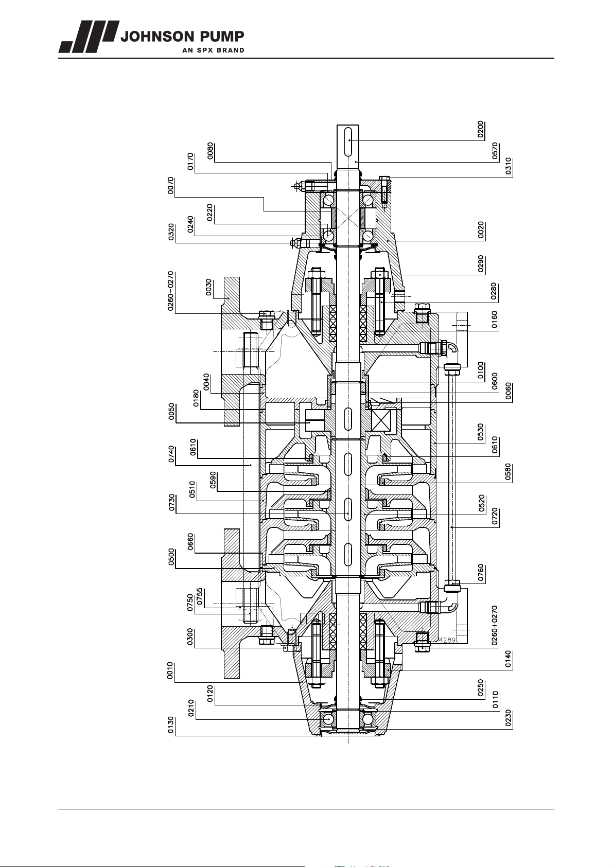
9.5 MCHZ 14a/b with heavy bearing construction
Figure 29: MCHZ 14a/b with heavy bearing construction.
64 Parts MCHZ/EN (0808) 4.1
Page 66
MCHZ
See figure 29.
Item no Quantity Description
0010 1 bearing housing cast iron
0020 1 bearing housing cast iron
0030 2 pump casing cast iron
0040 1 end cover cast iron
0050* 1 air wheel aluminium bronze
0060* 1 throttling bush bronze
0070 1 set ring steel
0080 1 bearing cover steel
0100* 3 external circlip alloyed steel
0110* 4 filling ring steel
0120 2 bearing cover steel
0130 1 bearing cover steel
0140 2 gland cast iron
0160* 10 gland packing ring -0170* 1 waved ring alloyed steel
0180* 1 gasket -0200* 1 key alloyed steel
0210* 1 ball bearing -0220* 2 ball bearing -0230* 4 external circlip steel
0240* 1 internal circlip steel
0250* 3 V-ring rubber
0260 4 plug steel
0270 4 wear ring copper
0280 4 stud alloyed steel
0290 4 nut brass
0300 4 tap bolt steel
0310 4 tap bolt steel
0320 2 grease nipple steel
0360 4 stud steel
0500 1 suction cover cast iron
0510 n-1 stage casing cast iron
0520* n impeller cast iron
0530 1 pump cover cast iron
0570* 1 shaft alloyed steel
0580* n wear ring bronze
0590* n-1 wear ring bronze
0600 1 throttling ring alloyed steel
0610* n-1 wear ring bronze
0660* n+3 gasket -0720 1 balance pipe copper
0730* n+1 key alloyed steel
0740 4 tie rod alloyed steel
0750 8 nut steel
0755 4 washer stainless steel
0760 2 angle pipe union brass
Cast iron Cast iron + bronze impeller
Design P Design Q
bronze
MCHZ/EN (0808) 4.1 Parts 65
Page 67
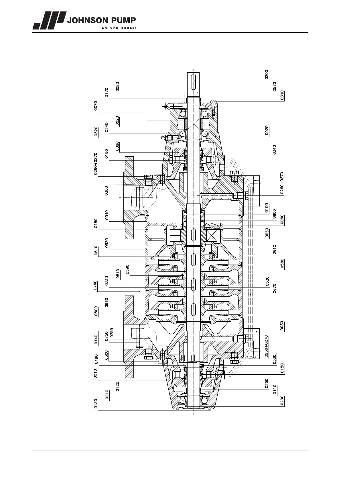
9.6 MCHZS 14a/b with heavy bearing construction
Figure 30: MCHZS 14a/b with heavy bearing construction.
66 Parts MCHZ/EN (0808) 4.1
Page 68
MCHZ
See figure 30.
Item no Quantity Description
0010 1 bearing housing cast iron
0020 1 bearing housing cast iron
0030 2 pump casing cast iron
0040 2 end cover cast iron
0050* 1 air wheel aluminium bronze
0060* 1 throttling bush bronze
0070 1 set ring steel
0080 1 bearing cover steel
0090 2 cover for mechanical seal cast iron
0100* 2 external circlip alloyed steel
0110* 4 filling ring steel
0120 2 bearing cover steel
0130 1 bearing cover steel
0140* 2 gasket -0150* 1 mechanical seal -0160* 1 mechanical seal -0170* 1 waved ring alloyed steel
0180* 1 gasket -0190 2 set ring alloyed steel
0200* 1 key alloyed steel
0210* 1 ball bearing -0220* 2 ball bearing -0230* 4 external circlip steel
0240* 1 internal circlip steel
0250* 3 V-ring rubber
0260 8 plug steel
0270 8 wear ring copper
0300 4 tap bolt steel
0310 4 tap bolt steel
0320 2 grease nipple steel
0330 2 adjustment screw alloyed steel
0340 2 pipe union brass
0360 4 tap bolt steel
0500 1 suction cover cast iron
0510 n-1 stage casing cast iron
0520* n impeller cast iron
0530 1 pump casing cast iron
0570* 1 shaft alloyed steel
0580* n wear ring bronze
0590* n-1 wear ring bronze
0600* 1 throttling ring alloyed steel
0610* n wear ring bronze
Cast iron
Design P Design Q
Cast iron + bronze
impeller
bronze
MCHZ/EN (0808) 4.1 Parts 67
Page 69
Item no Quantity Description
0660* n+3 gasket -0670 1 balance pipe copper
0730* n key alloyed steel
0740 4 tie rod alloyed steel
0750 8 nut steel
0755 4 washer stainless steel
Cast iron
Design P Design Q
Cast iron + bronze
impeller
68 Parts MCHZ/EN (0808) 4.1
Page 70
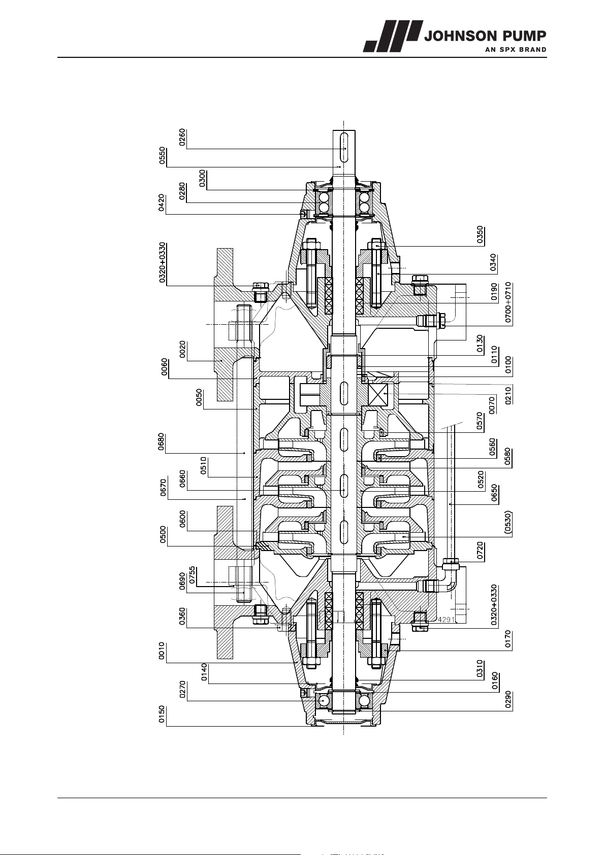
MCHZ
9.7 MCHZ 20a/b
Figure 31: MCHZ 20 a/b.
MCHZ/EN (0808) 4.1 Parts 69
Page 71
See figure 31.
item no. Quantity Description Material Remarks
0010 2 bearing housing cast iron
0020 2 pump casing cast iron
0050 1 pump casing cast iron
0060 1 end cover cast iron
0070 1 air wheel aluminium bronze
0100* 1 throttling bush bronze
0110* 1 throttling ring alloyed steel
0130* 3 external circlip alloyed steel
0140 3 bearing cover steel
0150 1 bearing cover steel
0160* 4 filling ring steel
0170 2 gland cast iron
0190* 10 gland packing ring -0210* 1 gasket -0260* 1 key alloyed steel
0270* 1 ball bearing -0280* 1 ball bearing -0290* 4 external circlip steel
0300* 2 internal circlip steel
0310* 3 V-ring rubber
0320 4 plug steel
0330 4 wear ring copper
0340 4 stud alloyed steel
0350 4 nut brass
0360 8 tap bolt steel
0420 2 plug steel
0500 1 suction cover cast iron
0510 n-1 stage casing cast iron
0520* n impeller cast iron
0550* 1 shaft alloyed steel
0560* n wear ring bronze
0570* n wear ring bronze
0580* n-1 wear ring bronze
0600* n+3 gasket -0650 1 balance pipe copper only for MCHZ 20a/b x 2 to 4
0660* n+1 key alloyed steel
0670 2 tie rod alloyed steel
0680 6 tie rod alloyed steel
0690 16 nut steel
0700 2 plug steel only for MCHZ 20a/b x 1
0710 2 wear ring copper only for MCHZ 20a/b x 1
0720 2 angle pipe union brass only for MCHZ 20a/b x 2 to 4
0755 16 washer stainless steel
bronze
70 Parts MCHZ/EN (0808) 4.1
Page 72
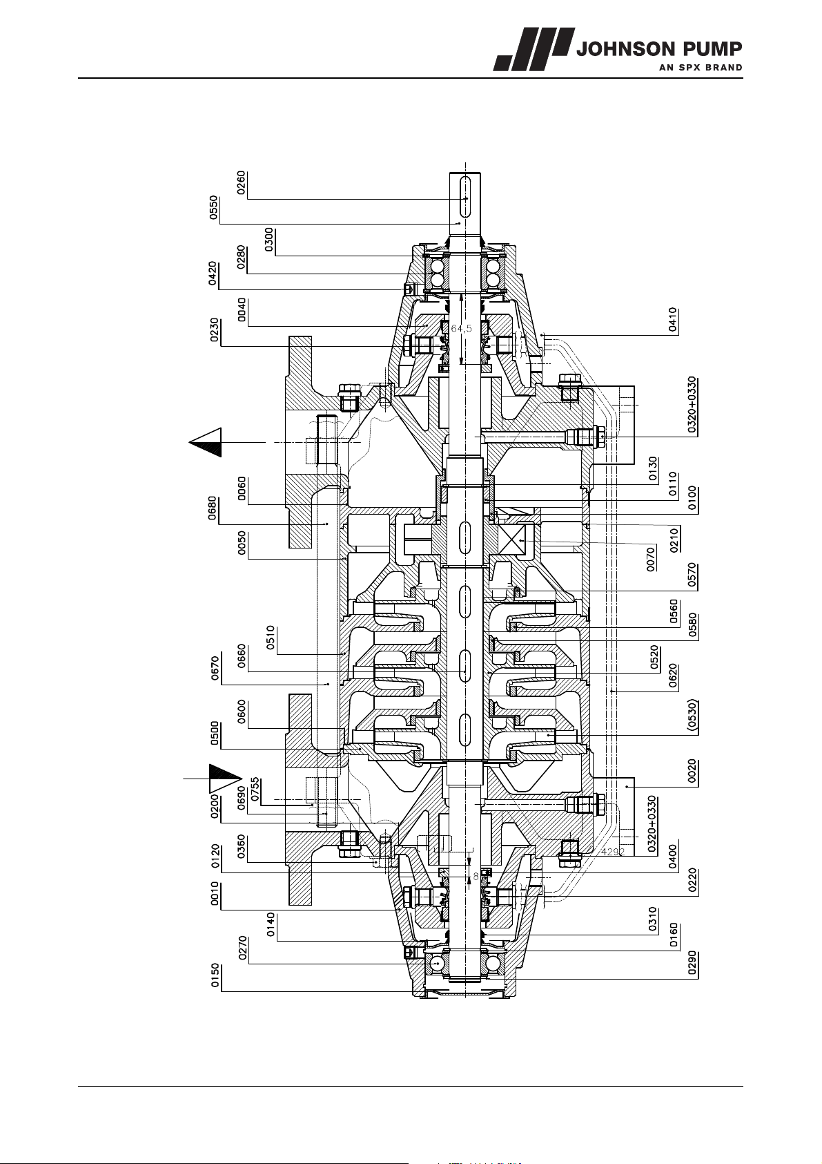
MCHZ
9.8 MCHZS 20a/b
Figure 32: MCHZS 20 a/b.
MCHZ/EN (0808) 4.1 Parts 71
Page 73
See figure 32.
item no. quantity description material
0010 2 bearing housing cast iron
0020 2 pump casing cast iron
0040 2 cover for mechanical seal cast iron
0050 1 pump casing cast iron
0060 1 end cover cast iron
0070* 1 air wheel aluminium bronze
0100* 1 throttling bush bronze
0110* 1 throttling ring alloyed steel
0120 2 set ring alloyed steel
0130* 3 external circlip alloyed steel
0140 3 bearing cover steel
0150 1 bearing cover steel
0160* 4 filling ring steel
0200* 2 gasket -0210* 1 gasket -0220* 1 mechanical seal -0230* 1 mechanical seal -0260* 1 key alloyed steel
0270* 1 ball bearing -0280* 1 ball bearing -0290* 4 external circlip steel
0300* 2 internal circlip steel
0310* 3 V-ring rubber
0320 10 plug steel
0330 10 sealing ring copper
0360 8 tap bolt steel
0400 2 adjustment screw alloyed steel
0410 2 pipe union brass
0420 2 plug steel
0500 1 suction cover cast iron
0510 n-1 stage casing cast iron
0520* n impeller cast iron bronze
0550* 1 shaft alloyed steel
0560* n wear ring bronze
0570* n wear ring bronze
0580* n-1 wear ring bronze
0600* n+3 gasket -0620 1 balance pipe copper
0660* n key alloyed steel
0670 2 tie rod alloyed steel
0680 6 tie rod alloyed steel
0690 16 nut steel
0755 16 washer stainless steel
72 Parts MCHZ/EN (0808) 4.1
Page 74
MCHZ
10 Technical data
10.1 Maximum speed
MCHZ - MCHZS
12,5 x 1 - 7 3600
12,5 x 8 - 9 3000
14a x 1 - 4 3600
14a x 5 - 6 3000 3600
14a x 7 - 8 3600
14a x 9 3000
14b x 1 - 4 3600
14b x 5 - 6 3000 3600
14b x 7 - 8 3600
14b x 9 3000
16 x 1 - 7 3600
16 x 8 - 9 3000
20a x 1 - 3 3600
20a x 4 3000
20b x 1 - 3 3600
20b x 4 3000
standard bearing
construction
n
max
[min-1]
heavy bearing
contruction
MCHZ/EN (0912) 4.2 Technical data 73
Page 75
10.2 Permissible pressure and temperature
MCHZ(S) 12,5 14a 14b 16 20a 20b
max. capacity [m3/h]
8 16 26 42 65 100
max. head [m] 275 250 255 350 250 160
max. inlet pressure [bar] 10
max. suction head [m]
(water of 15°C with air drawn in, discharged without
test pressure [bar] 1,5 x working pressure
min. test pressure [bar] 15
max. test pressure [bar] 50
max. permitted working
pressure
*)
[bar]
temperature range
MCHZS [°C]
*) Working pressure is the manometric head for Q=0, increased by the pre-pressure.
8
back-pressure)
40 - (3x inlet pressure)
-20°C to +120°C
74 Technical data MCHZ/EN (0912) 4.2
Page 76

MCHZ
10.3 Hydraulic performance
10.3.1 Performance overview 3000 min
-1
Figure 33: Performance overview 3000 min
MCHZ/EN (0912) 4.2 Technical data 75
-1
.
Page 77
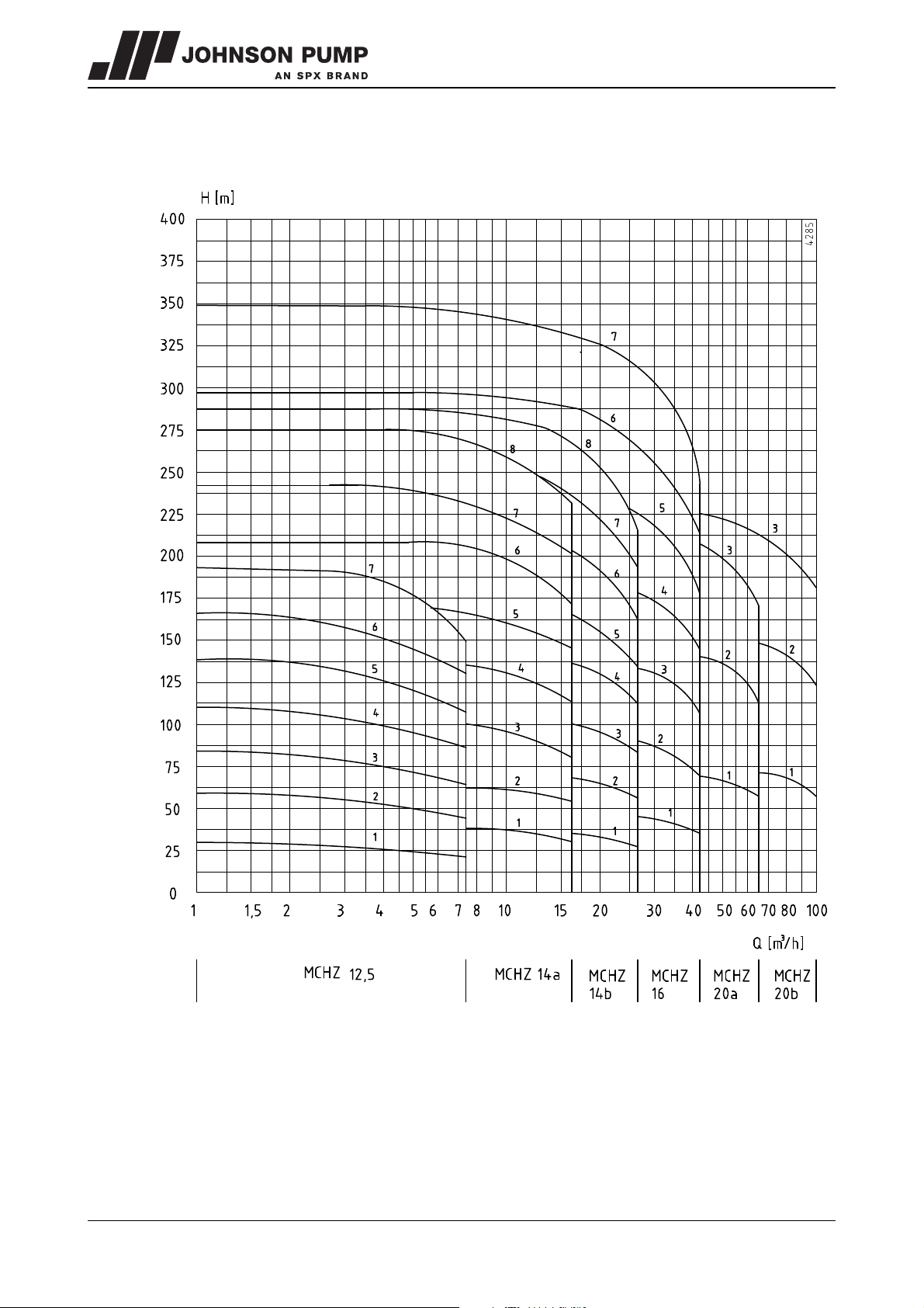
10.3.2 Performance overview 3600 min-1
Figure 34: Performance overview 3600 min
-1
.
76 Technical data MCHZ/EN (0912) 4.2
Page 78
MCHZ
10.4 Tightening moments for bolts and nuts
Materials 8.8 A2, A4
Thread Tightening moment [Nm]
M6 9 6
M8 20 14
M10 40 25
M12 69 43
M16 168 105
10.5 Tie rod torque
Pump type Torque [Nm] Screwthread Material
MCHZ(S) 12,5 89 - 118 M16
MCHZ(S) 14a/b 99 - 133 M16
MCHZ(S) 16 200 - 267 M20
MCHZ(S) 20a/b 137 - 183 M20
10.6 Post-greasing of ball bearings
See the table below for bearings that require post-greasing and the appropriate type of
grease.
40CrMo4
Pump type Bearings
MCH(S) 14 a/b
with reinforced
bearing
MCH(S) 16
10.7 Recommended locking liquids
Description Locking liquid
throttling bush Loctite 641
wear rings Loctite 641
suction side bearing
all bearings
Post-grease with one of the following
types of grease (classification acc. to
NLGI-2)
BP Energrease LS2, Gulf Crown Grease nr 2,
Chevron Polyurea EP Grease 2, Mobil
Mobilux EP2, Esso Beacon 2, Shell Alvania
R2, Fina Marson L2, Total Multis EP22,
Texaco Multifak EP2, SKF Alfalub LGMT 3
MCHZ/EN (0912) 4.2 Technical data 77
Page 79
10.8 Noise data
54
56
58
60
62
64
66
68
70
72
74
76
78
80
82
84
86
88
90
92
94
96
98
0,1
1
10
100
200
P [kW]
[dB(A)]
A
4103_A
B
60
65
70
75
80
85
90
95
100
0,1
1
10
100
300
P [kW]
[dB(A)]
4104_A
A
B
10.8.1 Pump noise as a function of pump power
Figure 35: Noise level as function of pump power [kW] at 1450 min
-1
A = sound energy, B = sound pressure.
Figure 36: Noise level as function of pump power [kW] at 2900 min
A = sound energy, B = sound pressure.
78 Technical data MCHZ/EN (0912) 4.2
-1
Page 80
MCHZ
4102
L [dB]
|L1 - L2| [dB]
01234567891011121314151617181920
3,2
3,0
2,8
2,6
2,4
2,2
2,0
1,8
1,6
1,4
1,2
1,0
0,8
0,6
0,4
0,2
0,0
10.8.2 Noise level of entire pump unit
Figure 37: Noise level of entire pump unit.
In order to determine the total noise level of the entire pump unit, the noise level of the
motor must be added to that of the pump. This can be easily done by using the graph
above.
1 Determine the noise level (L1) of the pump, see figure 35 or figure 36.
2 Determine the noise level (L2) of the motor, see documentation of the motor.
3 Determine the difference between both levels |L1 - L2|.
4 Find the differential value on the |L1 - L2|-axis and go up to the curve.
5 From the curve go left to the L[dB] -axis and read out the value.
6 Add this value to the highest value of both noise levels (L1 or L2).
Example:
1. Pump 75 dB; motor 78 dB.
2. |75-78| = 3 dB.
3. 3 dB on the X-axis = 1,75 dB on the Y-axis.
4. Highest noise level + 1,75 dB = 78 + 1,75 = 79,75 dB.
MCHZ/EN (0912) 4.2 Technical data 79
Page 81
80 Technical data MCHZ/EN (0912) 4.2
Page 82
MCHZ
Index
A
Accessories . . . . . . . . . . . . . . . . . . . . . . . . .18
Application area . . . . . . . . . . . . . . . . . . . . . 16
Applications . . . . . . . . . . . . . . . . . . . . . . . . . 13
Axial forces . . . . . . . . . . . . . . . . . . . . . . . . . 15
B
Balance holes . . . . . . . . . . . . . . . . . . . . . . .15
Balance pipe . . . . . . . . . . . . . . . . . . . . . . . .16
Ball bearings
post-greasing . . . . . . . . . . . . . . . . . . . .77
Basic type . . . . . . . . . . . . . . . . . . . . . . . . . . 13
Bearing construction . . . . . . . . . . . . . . . . . 15
Bearing groups . . . . . . . . . . . . . . . . . . . . . .14
C
Construction . . . . . . . . . . . . . . . . . . . . . . . .15
Coupling
alignment . . . . . . . . . . . . . . . . . . . . . . .19
alignment tolerances . . . . . . . . . . . . . . 20
D
Daily maintenance . . . . . . . . . . . . . . . . . . . .23
mechanical seal . . . . . . . . . . . . . . . . . .23
stuffing box packing . . . . . . . . . . . . . .23
E
Earthing . . . . . . . . . . . . . . . . . . . . . . . . . . . .17
Electric motor
connection . . . . . . . . . . . . . . . . . . . . . .20
Environment . . . . . . . . . . . . . . . . . . . . . . . .17
Environmental influences . . . . . . . . . . . . . .23
F
Faults . . . . . . . . . . . . . . . . . . . . . . . . . . . . . .24
Foundation . . . . . . . . . . . . . . . . . . . . . . . . .17
G
Guarantee . . . . . . . . . . . . . . . . . . . . . . . . . .10
H
Hoisting . . . . . . . . . . . . . . . . . . . . . . . . . . . . 11
I
Impellers . . . . . . . . . . . . . . . . . . . . . . . . . . . 15
Inspection
motor . . . . . . . . . . . . . . . . . . . . . . . . . . 21
pump . . . . . . . . . . . . . . . . . . . . . . . . . . 21
L
Lifting eye . . . . . . . . . . . . . . . . . . . . . . . . . . 11
Liquid
drain . . . . . . . . . . . . . . . . . . . . . . . . . . . 27
Liquids . . . . . . . . . . . . . . . . . . . . . . . . . . . . . 15
Lubrication of the bearings . . . . . . . . . . . . 24
M
Maintenance staff . . . . . . . . . . . . . . . . . . . . . 9
Mechanical seal . . . . . . . . . . . . . . . . . . . . . 22
Monitoring . . . . . . . . . . . . . . . . . . . . . . . . . . 22
N
Noise . . . . . . . . . . . . . . . . . . . . . . . . . . .22, 24
O
Operational range . . . . . . . . . . . . . . . . . . . 75
P
Pallets . . . . . . . . . . . . . . . . . . . . . . . . . . . . . 10
Piping . . . . . . . . . . . . . . . . . . . . . . . . . . . . . 18
assemble . . . . . . . . . . . . . . . . . . . . . . . 19
Power supply
switch off . . . . . . . . . . . . . . . . . . . . . . . 27
Precautionary measures . . . . . . . . . . . . . . 27
Pressure . . . . . . . . . . . . . . . . . . . . . . . . . . . 74
Pump description . . . . . . . . . . . . . . . . . . . . 13
Pump section . . . . . . . . . . . . . . . . . . . . . . . 15
MCHZ/EN (0912) 4.2 81
Page 83
Pump unit
assembly . . . . . . . . . . . . . . . . . . . . . . .19
commissioning . . . . . . . . . . . . . . . . . . . 21
installation . . . . . . . . . . . . . . . . . . . . . .19
R
Recommended locking liquid . . . . . . . . . .77
Re-use . . . . . . . . . . . . . . . . . . . . . . . . . . . . .16
S
Safety . . . . . . . . . . . . . . . . . . . . . . . . . . . .9, 17
symbols . . . . . . . . . . . . . . . . . . . . . . . . . 9
Scrapping . . . . . . . . . . . . . . . . . . . . . . . . . .16
Self-priming section . . . . . . . . . . . . . . . . . .15
Sense of rotation . . . . . . . . . . . . . . . . . . . .21
Serial number . . . . . . . . . . . . . . . . . . . . . . .14
Shaft seal . . . . . . . . . . . . . . . . . . . . . . . . . . .16
Special tools . . . . . . . . . . . . . . . . . . . . . . . .27
Start-up . . . . . . . . . . . . . . . . . . . . . . . . . . . .22
Static electricity . . . . . . . . . . . . . . . . . . . . .17
Storage . . . . . . . . . . . . . . . . . . . . . . . . 10, 11
Stuffing box packing
adjustment . . . . . . . . . . . . . . . . . . . . . . 22
T
Technicians . . . . . . . . . . . . . . . . . . . . . . . . . . 9
Temperature . . . . . . . . . . . . . . . . . . . . . . . . 74
Tie rod torque . . . . . . . . . . . . . . . . . . . . . . . 77
Tightening moments
for bolts and nuts . . . . . . . . . . . . . . . . .77
Transport . . . . . . . . . . . . . . . . . . . . . . . . . . .10
Type description . . . . . . . . . . . . . . . . . . . . .14
V
Ventilation . . . . . . . . . . . . . . . . . . . . . . . . . .17
W
Working switch . . . . . . . . . . . . . . . . . . . . . . 20
82 MCHZ/EN (0912) 4.2
Page 84
Order form for spare parts
FAX Nr.
ADDRESS
Your order will only be dealt with if this order form has been correctly completed and signed.
Order date:
Your order number:
Pump type:
Execution:
Quantity Item. No. Part Article number pump
Delivery address: Invoicing address:
Ordered by: Signature: Telephone:
ORDFORM (0804) 3.1 EN 83
Page 85
84 ORDFORM (0804) 3.1 EN
Page 86

Your local contact:
SPX Process Equipment NL B.V.
Dr. A. F. Philipsweg 51, 9403 AD Assen, THE NETHERLANDS
P.O. Box 9, 9400 AA Assen, THE NETHERLANDS
Phone: + 31 (0) 592 37 67 67 Fax: + 31 (0) 592 37 67 60
E-Mail: [email protected]
For more information about our worldwide locations, approvals, certifications, and local representatives, please visit
www.johnson-pump.com / www.spxpe.com.
SPX Corporation reserves the right to incorporate our latest design and material changes without notice or obligation. Design
features, materials of construction and dimensional data, as described in this bulletin, are provided for your information only
and should not be relied upon unless confirmed in writing.
Copyright © 2005, 2009 SPX Corporation
 Loading...