

Johnson Controls VB30, VB24, VB36, VM09, VM12 Installation, Operation And Maintenance Manual
...Page 1
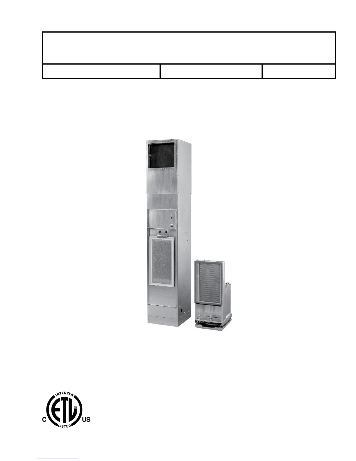
INDOOR PACKAGED EQUIPMENT
Installation, Operation, and Maintenance Supersedes: 145.18-IOM1 (115) Form 145.18-IOM1 (818)
HIGH EFFICIENCY VSCS SERIES
VERTICAL STACKED WATER SOURCE HEAT PUMP
LD27626
CABINET MODEL VB/VM/VS09–36
AND
CHASSIS MODEL VSCS09–36
R-410A
ISSUE DATE:
August 30, 2018
Page 2
FORM 145.18-IOM1
ISSUE DATE: 8/30/2018
IMPORTANT!
READ BEFORE PROCEEDING!
GENERAL SAFETY GUIDELINES
This equipment is a relatively complicated apparatus.
During rigging, installation, operation, maintenance,
or service, individuals may be exposed to certain components or conditions including, but not limited to:
heavy objects, refrigerants, materials under pressure,
rotating components, and both high and low voltage.
Each of these items has the potential, if misused or
handled improperly, to cause bodily injury or death. It
is the obligation and responsibility of rigging, installation, and operating/service personnel to identify and
recognize these inherent hazards, protect themselves,
and proceed safely in completing their tasks. Failure
to comply with any of these requirements could result
in serious damage to the equipment and the property in
which it is situated, as well as severe personal injury or
death to themselves and others at the site.
This document is intended for use by owner-authorized
rigging, installation, and operating/service personnel. It
is expected that these individuals possess independent
training that will enable them to perform their assigned
tasks properly and safely. It is essential that, prior to
performing any task on this equipment, this individual
shall have read and understood the on-product labels,
this document and any referenced materials. This individual shall also be familiar with and comply with
all applicable industry and governmental standards and
regulations pertaining to the task in question.
SAFETY SYMBOLS
The following symbols are used in this document to alert the reader to specific situations:
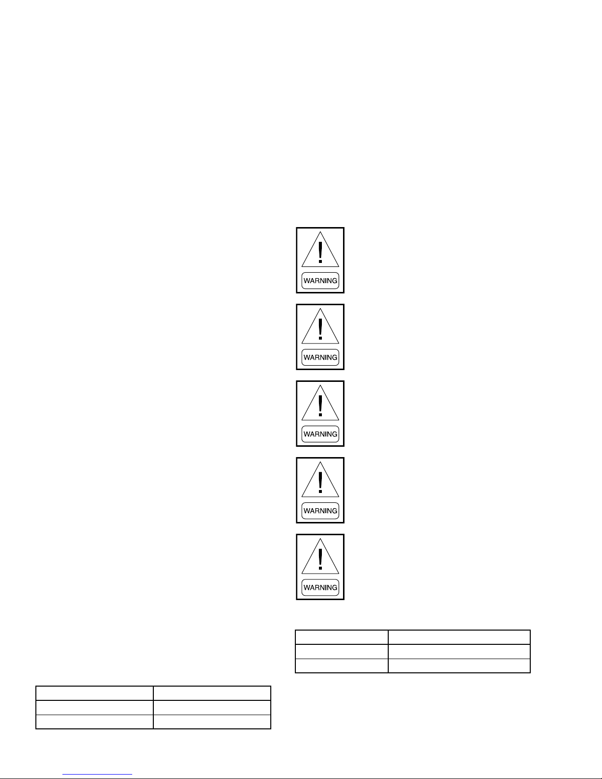
Indicates a possible hazardous situation
which will result in death or serious injury
if proper care is not taken.
Identies a hazard which could lead to
damage to the machine, damage to other
equipment and/or environmental pollution if proper care is not taken or instructions and are not followed.
Indicates a potentially hazardous situation which will result in possible injuries
or damage to equipment if proper care is
not taken.
External wiring, unless specied as an optional connection in the manufacturer’s product line, is not
to be connected inside the control cabinet. Devices such as relays, switches, transducers and controls
and any external wiring must not be installed inside the micro panel. All wiring must be in accor-
dance with the manufacturer's published specications and must be performed only by a qualied
electrician. The manufacturer will NOT be responsible for damage/problems resulting from improper
connections to the controls or application of improper control signals. Failure to follow this warn-
ing will void the manufacturer’s warranty and cause serious damage to property or personal injury.
WARNING: This product can expose you to chemicals including formaldehyde, which is known
to the state of California to cause cancer. For more information, go to www.P65Warnings.ca.gov.
2
Highlights additional information useful
to the technician in completing the work
being performed properly.
Page 3

FORM 145.18-IOM1
ISSUE DATE: 8/30/2018
CHANGEABILITY OF THIS DOCUMENT
In complying with the manufacturer's’ policy for continuous product improvement, the information contained in this document is subject to change without
notice. There is no commitment to update or provide
lifting, and operating/service personnel should verify
whether the equipment has been modified and if current
literature is available from the owner of the equipment
prior to performing any work on the equipment.
current information automatically to the manual or
product owner. Updated manuals, if applicable, can be
CHANGE BARS
obtained by contacting the nearest service office.
Revisions made to this document are indicated with a
It is the responsibility of rigging, lifting, and operating/
service personnel to verify the applicability of these
documents to the equipment. If there is any question
regarding the applicability of these documents, rigging,
line along the left or right hand column in the area the
revision was made. These revisions are to technical in-
formation and any other changes in spelling, grammar
or formatting are not included.
ASSOCIATED LITERATURE
MANUAL DESCRIPTION FORM NUMBER
Vertical Stacked Heat Pump Start-Up and Performance Checklist 145.18-CL1
Vertical Stacked Water Source Heat Pump Heating and Cooling Data Record Sheet 145.18-CL2
3
Page 4
FORM 145.18-IOM1
ISSUE DATE: 8/30/2018
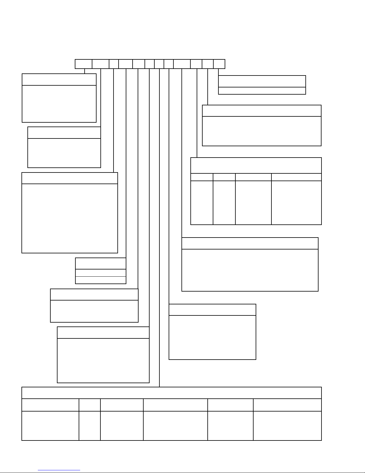
CABINET NOMENCLATURE
1, 2 3, 4 5 6 7 8 9 10 11, 12 13 14 15
VB 12 M 1 D E A 2 2T 4 0 C
PRODUCT CATEGORY
VB = Vertical Stacked Heat Pump -
Standard Cabinet Assembly
VM = Vertical Stacked Heat Pump -
Master Cabinet Assembly
VS = Vertical Stacked Heat Pump -
Satellite Cabinet Assembly
UNIT CAPACITY
09 = 0.75 TON 24 = 2 TON
12 = 1 TON 30 = 2.5 TON
15 = 1.25 TON 36 = 3 TON
18 = 1.5 TON
CONTROL OPTIONS
M = Microprocessor (MP) Control with 2-Speed
Unit Mounted Switch
2 = MP Control with 2-Speed Thermostat Control
3 = MP Control with 3-Speed Thermostat Control
P = MP Control with Surface-Mount Thermostat
Connection with Unit Mounted Switch
4 = MP Control with Surface-Mount Thermostat
Connection with 2-Speed Thermostat Control
5 = MP Control with Surface-Mount Thermostat
Connection with 3-Speed Thermostat Control
(ECM Only)
VOLTAGE
1 = 208/230-60-1
6 = 265-60-1
ELECTRICAL CONNECTION
0 = None (Terminal Block)
D = Non-Fused Disconnect
F = Disconnect with Fuses
BLOWER OPTIONS
A = PSC Blower
B = Hi-Static PSC Blower
E = ECM Blower
F = Hi-Static ECM Blower
G = ECM with Continuous Low Speed
H = Hi-Static ECM with Continuous Low Speed
DESIGN SERIES
C = Current Generation
MISCELLANEOUS OPTIONS
0 = None
S = Stainless Steel (SST) Drain Pan
F = MERV 8 Filters
C = SST Drain Pan with MERV 8 Filters
HORIZONTAL DISCHARGE OPENING
ORIENTATION
00, 0T 1H, 1T 2H, 2T 3H, 3T
X = None B = Back 1 = Left + Front 7 = Front + Left + Right
F = Front 2 = Left + Back 8 = Front + Right + Back
L = Left 3 = Left + Right 9 = Front + Left + Back
R = Right 4 = Right + Back
5 = Right + Front
6 = Back + Front
SUPPLY AIR CONFIGURATION
1H = Single Horizontal Supply 2T = Double Horizontal Supply
2H = Double Horizontal Supply
3H = Triple Horizontal Supply 3T = Triple Horizontal Supply
0T = Top Only
1T = Single Horizontal Supply
+ Top
+ Top
+ Top
00 = Field Cut (No Openings)
RISER ARRANGEMENT
1 = Right Hand Risers
2 = Left Hand Risers
3 = Back Risers
4 = Right Hand Risers with Cover
5 = Left Hand Risers with Cover
6 = Back Risers with Cover
CABINET OPTIONS
Cabinet Height
88 inches A G L R W
80 inches B H M T X
80 inches with 4-inch Stand D K P V Z
80 inches with 8-inch Stand F 2 4 6 8
No OA
Options
Left Top OA Entry
(4-inch Round)
4
Left Top OA Entry (4-inch
Round with Motorized Damper)
Right Top OA Entry
(4-inch Round)
Right Top OA Entry (4-inch
Round with Motorized Damper)
Page 5
FORM 145.18-IOM1
ISSUE DATE: 8/30/2018
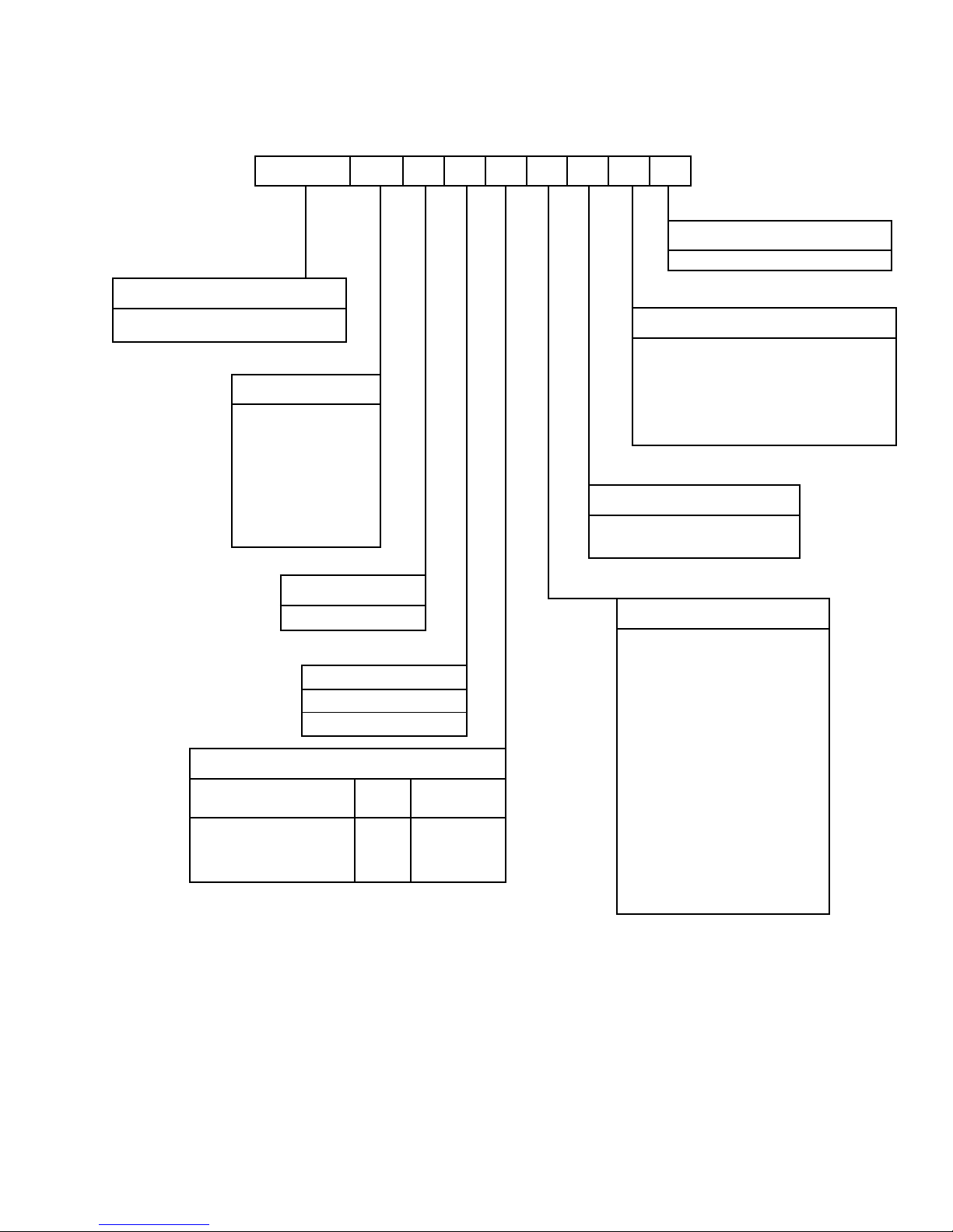
1, 2, 3, 4 5, 6 7 8 9 10 11 12 13
VSCS 12 C 1 0 0 A C 0
PRODUCT CATEGORY
VSCS = Vertical Stacked Heat Pump Chassis
R-410A
UNIT CAPACITY
09 = 0.75 TON
12 = 1 TON
15 = 1.25 TON
18 = 1.5 TON
24 = 2 TON
30 = 2.5 TON
36 = 3 TON
CHASSIS NOMENCLATURE
MISCELLANEOUS OPTIONS
O = None
WATERSIDE OPTIONS
C = Standard Water Coil
B = Standard Water Coil with Low Temperature
Option
N = Cupro-Nickel Water Coil
R = Cupro-Nickel Water Coil with Low Temperature
Option
AIRSIDE OPTIONS
A = Standard Airside Coil
C = Corrosion Protective Coating
DESIGN SERIES
C = Current Generation
VOLTAGE
1 = 208/230-60-1
6 = 265-60-1
WATER VALVE & PUMP OPTIONS
VALVE OPTIONS
No Water Control Valve
Motorized 2-Way Shut-Off Valve
Motorized 3-Way Shut-Off Valve
VALVE
ONLY
Y-STRAINER
O S
M Y
N V
AUTO-FLOW REGULATOR
0 = No Flow Control Valve
B = 1.5 USGPM
C = 2.0 USGPM
D = 2.5 USGPM
E = 3.0 USGPM
F = 3.50 USGPM
H = 4.0 USGPM
J = 4.5 USGPM
K = 5.0 USGPM
L = 6.0 USGPM
M = 7.0 USGPM
N = 8.0 USGPM
P = 9.0 USGPM
R = 10.0 USGPM
5
Page 6

FORM 145.18-IOM1
ISSUE DATE: 8/30/2018
TABLE OF CONTENTS
SECTION 1 - INSTALLATION ..................................................................................................................................9
Notice and Disclaimer ......................................................................................................................................9
Disclaimer ................................................................................................................................................9
Pre-Installation .................................................................................................................................................9
Literature .................................................................................................................................................9
Shipping ..................................................................................................................................................9
Inspection and Storage .........................................................................................................................10
Preparations for Installing the Unit ........................................................................................................10
Rigging .................................................................................................................................................. 11
Cabinet Riser Installation ............................................................................................................................... 11
Placing the Cabinet ............................................................................................................................... 11
Riser Loop ...................................................................................................................................................... 16
Hoses .............................................................................................................................................................16
Electrical Wiring .............................................................................................................................................. 18
Field-Installed Power Wiring ..................................................................................................................18
Field-Installed Low Voltage Wiring ........................................................................................................18
Optional Surface Mount Thermostat Connection Wiring ....................................................................... 19
Optional Remote Mounted Thermostat Wiring ...................................................................................... 19
Optional ADA Door Mounted Thermostat .............................................................................................. 20
EC Motor (ECM) Continuous Fan .........................................................................................................20
Closet and Drywall Installation .......................................................................................................................20
Acoustic Return Air (RA) Panel ......................................................................................................................20
Supply Air (SA) Ductwork ............................................................................................................................... 24
Horizontal Supply Air ............................................................................................................................. 24
Top Discharge Supply Air ......................................................................................................................24
Top Mounted Fresh Air Intake ........................................................................................................................27
Top Mounted Fresh Air Intake with Motorized Damper .........................................................................27
System Flushing and Cleaning ...................................................................................................................... 28
Flushing the System .............................................................................................................................. 28
Cleaning the System .............................................................................................................................29
Chassis Installation ........................................................................................................................................32
For Units with NPSH Valve Connection and Hose Sets ........................................................................ 32
For Units with NPT Style (Tapered Pipe Thread) Valve Connection and Hoses ...................................32
SECTION 2 - OPERATION .....................................................................................................................................35
Pre-Start-Up Checklist .................................................................................................................................... 35
Initial Unit Start-Up .........................................................................................................................................35
System Loop Temperature .............................................................................................................................36
Fan Speed Adjustment ................................................................................................................................... 36
Unit Controls ................................................................................................................................................... 40
Sequence of Operation .........................................................................................................................40
Continuous Blower ................................................................................................................................40
Safety Control Reset .............................................................................................................................40
Operation Errors .................................................................................................................................... 41
Safety Controls ...................................................................................................................................... 41
Random Start ........................................................................................................................................42
Compressor Protection ..........................................................................................................................42
Microprocessor Control Unit Flash Codes .............................................................................................42
Communication ....................................................................................................................................42
6
Page 7

FORM 145.18-IOM1
ISSUE DATE: 8/30/2018
TABLE OF CONTENTS (CONT'D)
SECTION 3 - MAINTENANCE ................................................................................................................................ 43
APPENDIX ..............................................................................................................................................................45
Heating and Cooling Data Record Sheet .......................................................................................................49
R-410A Quick Reference Guide ..................................................................................................................... 51
LIST OF FIGURES
FIGURE 1 - Ideal Riser Insertion Depth ..................................................................................................................12
FIGURE 2 - Correct/Incorrect Stub-Out Positions in Cabinet Riser Opening ..........................................................12
FIGURE 3 - Cabinet Unit Dimensions & Floor Sleeve Dimensions .........................................................................14
FIGURE 4 - Cabinet Riser Dimensions ...................................................................................................................15
FIGURE 5 - Standard Factory Supplied NPSH Hose Kits and Risers.....................................................................17
FIGURE 6 - Optional Field Supplied Risers with Factory Supplied NPSH Hose Kits and Shut-Off Valves .............17
FIGURE 7 - Conversion of NPT to NPSH Type Fittings (VB Units with NPT Fittings Only) ....................................18
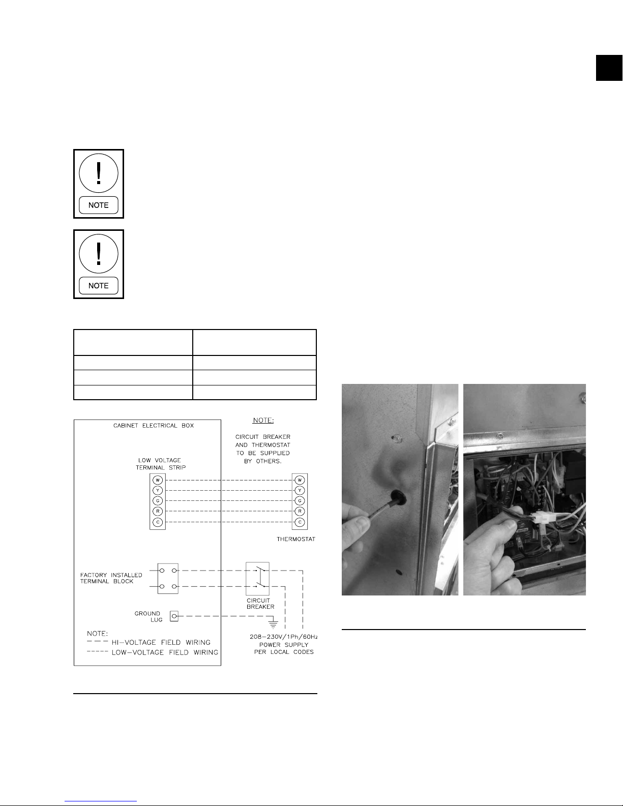
FIGURE 8 - Field Wiring Diagram ...........................................................................................................................19
FIGURE 9 - Remote Thermostat Wiring ..................................................................................................................19
FIGURE 10 - Unit Switch Plate with ADA Thermostat Connection .......................................................................... 20
FIGURE 11 - Critical Return Air (RA) Panel with Unit Cabinet Installation Dimensions ..........................................21
FIGURE 12 - RA Panel Cross Section Installation at Floor Level ...........................................................................22
FIGURE 13 - RA Panel Dimensions ........................................................................................................................22
FIGURE 14 - Optional RA Panel with ADA Mounted Thermostat ............................................................................23
FIGURE 15 - Supply Grille with Volume Damper and 1/8-inch Neoprene Tape Applied to Perimeter ....................24
FIGURE 16 - Unit Mounted Supply Grille Installation ..............................................................................................25
FIGURE 17 - Damper Plate Fasteners ....................................................................................................................27
FIGURE 18 - Remove the Red Cover .....................................................................................................................27
FIGURE 19 - Position Black Cover..........................................................................................................................28
FIGURE 20 - System Flushing and Cleaning ..........................................................................................................29
FIGURE 21 - Fresh Air Opening without Motorized Damper – Left and Right Hand Unit Shown ...........................30
FIGURE 22 - Fresh Air Opening with Motorized Damper – Left and Right Hand Unit Shown ................................31
FIGURE 23 - Lift the Chassis Front .........................................................................................................................33
FIGURE 24 - Tilt the Chassis ..................................................................................................................................33
FIGURE 25 - Insert the Chassis ..............................................................................................................................33
FIGURE 26 - Pivot the Chassis ...............................................................................................................................34
FIGURE 27 - Slide the Chassis ...............................................................................................................................34
FIGURE 28 - Check the Chassis .............................................................................................................................34
FIGURE 29 - PSC Motor Wiring Diagram ...............................................................................................................45
FIGURE 30 - ECM Wiring Diagram .........................................................................................................................46
FIGURE 31 - Continuous Fan with ECM Wiring Diagram .......................................................................................47
FIGURE 32 - Motorized Damper ECM Wiring Diagram ..........................................................................................48
7
Page 8

FORM 145.18-IOM1
ISSUE DATE: 8/30/2018
LIST OF TABLES
TABLE 1 - High Series Physical Data .....................................................................................................................13
TABLE 2 - Replacement Hose Gaskets ..................................................................................................................16
TABLE 3 - Chassis Hoses .......................................................................................................................................16
TABLE 4 - Typical Wire Connections ......................................................................................................................19
TABLE 5 - Unit Supply Opening Sizes ....................................................................................................................26
TABLE 6 - Unit Supply Face Velocity (FPM) ...........................................................................................................26
TABLE 7 - Operating Limits ....................................................................................................................................36
TABLE 8 - PSC Standard Blower Performance (CFM) ...........................................................................................37
TABLE 9 - PSC High Static Blower Performance (CFM) ........................................................................................37
TABLE 10 - ECM Standard Blower Performance (CFM) ........................................................................................38
TABLE 11 - ECM High Static Blower Performance (CFM) ......................................................................................38
TABLE 12 - ECM Blower Performance - All Speed Taps (CFM) ............................................................................. 39
TABLE 13 - Flash Codes ........................................................................................................................................42
8
Page 9

FORM 145.18-IOM1
ISSUE DATE: 8/30/2018
SECTION 1 - INSTALLATION
After installing the unit, show the user
how to turn off the electricity to the unit.
Point out control and switch locations for
turning off the electricity.
Ensure the user understands the importance of following all safety precautions.
NOTICE AND DISCLAIMER
This unit contains refrigerant installed by the factory
that is approved for use in the unit’s intended country
of installation or market. Distributors are only authorized to provide refrigerants that have been approved
for use in the countries or markets they serve.
The refrigerant used in this unit is identified on the
unit's nameplate and in this manual. Any additions of
refrigerant into this unit must comply with the country’s requirements with regard to refrigerant use and
should be obtained from manufacturer approved distributors. Use of unapproved refrigerant substitutes
will void all warranties and can cause injury or death.
1
Modifications may invalidate product certifications or
violate country standards. Any person or entity making
changes to the product is responsible for obtaining the
required engineering review and approval, as well as
covering certification and other related costs.
Unauthorized customer modifications to certified
products are prohibited for the following reasons:
A. Modications may create hazards that could result
in death, serious injury, or equipment damage.
B. Modications will void product warranties.
C. Modications may invalidate product certica-
tions and may violate country standards. Country
standards may require that only certied products
be used in certain applications, and modications
that result in the loss of product certication may
violate those standards.
PRE-INSTALLATION
Literature
Disclaimer
Customer modifications to certified products are prohibited. If performed without the express written approval of the manufacturer, modifications will void
all warranties (expressed or implied) and may result
in hazardous situations resulting in equipment damage,
serious physical injury or property damage, or death.
The manufacturer has certified the product as being
compliant with applicable government and/or industry
standards. Product certification is designated either on
the product itself or in the product literature. The certification mark identifies the applicable standards as
well as the Nationally Recognized Test Lab (NRTL) or
other testing facility that conducted the testing, where
applicable.
If changes are made to the product, an engineering review is required to assess the impact to the product certification. In some instances, the changes may require
that the NRTL or testing facility review and re-approve
the product by means of a field or site inspection and
certification.
Review this Installation, Operation, and Maintenance
(IOM) manual prior to installation. After installing the
unit, give this IOM to the end user. If help is needed
with any of the installation instructions or matters relating to the unit, contact the sales office where you
bought the unit. You may also refer to the unit rating
plate for a contact name.
Shipping
Cabinets and risers ship in one of the following configurations:
• Cabinets are stacked on their side with risers attached. Chassis ship on separate skids.
• Risers ship loose, packaged in boxes and sorted
by oor. Cabinets ship upright up to four per skid.
Chassis ship on separate skids.
• Risers ship loose, packaged in boxes, and sorted
by oor. Cabinets ship upright on skids with chassis inside the cabinet. Chassis electrical and water
connections are not installed. The chassis is secured to the service panel. Remove the screws before removing the service panel and chassis.
The cabinet must remain standing upright. Do not
place cabinets on their side with the chassis inside.
9
Page 10
SECTION 1 - INSTALLATION
FORM 145.18-IOM1
ISSUE DATE: 8/30/2018
Inspection and Storage
Store cabinets, chassis, and risers the same way they
were shipped. Ensure the storage area is dry and protected from the environment. Keep the units in their
upright position. If the risers are stored at the job site,
ensure the pipe ends are capped to prevent foreign object debris and contamination.
In areas where construction is not complete (including
dry wall, plaster, paint, and where any emission of dust
particulates or fumes from outgassing are present), all
precautions must be taken to protect the cabinet, openings, and chassis from contamination or physical damage.
Upon delivery, perform the following inspections:
1. Inspect the unit for shipment damage. Notify the
Transportation Company of any damage and note
the damage on the shipping receipt.
Rough handling may dislocate and damage internal components.
• Remove the inner service panel and manually
check the blower wheel for free rotation.
• Match the refrigeration chassis to the proper cabinets by referring to the cabinet and chassis nameplate and label information.
• Remove the chassis refrigeration access panel
(top cover) and inspect the unit. Ensure that the
refrigerant tubing is free from obvious physical
damage and kinks, and check that piping does not
touch other unit components.
• Ensure the compressor is mounted on neoprene
isolators with metal spacing sleeves inside. Secured it with nuts that are snug against the metal
spacer sleeves.
• Inspect all electrical connections. Connections
must be clean and tight at the terminals.
Do NOT use the risers to lift the cabinet
assembly.
2. Inspect the riser projections at each end of the
cabinet for misalignment or end damage that
would prevent making an acceptable connection.
3. Inspect the thermostats and other accessories that
have been shipped separately for quantity and
transit damage.
Store the refrigeration chassis in the normal upright
orientation to maintain oil in the compressor sump.
Preparations for Installing the Unit
Before installing the unit, perform the following preparations:
• Verify the model number on the unit nameplate
with the ordering and shipping information to ensure the correct unit has been shipped.
• Carefully inspect each unit before delivery to the
installation site. All cabinets may not be equipped
with the same size riser or the same air supply
grille arrangement. In most cases, each cabinet is
individually tagged for a specic location in the
building.
Do NOT install this unit outdoors.
A compressor/unit comprises a pressurized system. Never loosen threaded joints
while the system is under pressure, and
never open pressurized system parts.
Before servicing, open and tag all disconnect switches.
Do NOT install units in a flammable
environment due to the danger of an
explosion.
• Keep the cabinet sealed with the shipping materials until all plastering, painting, and construction
work is complete.
10
Page 11
FORM 145.18-IOM1
ISSUE DATE: 8/30/2018
SECTION 1 - INSTALLATION
Safety guards, shields, barriers, covers, and protective devices must not be
removed while the compressor/unit is
operating.
All safety features, disengagement, and
interlocks must be in place and function
correctly before the equipment is put into
operation. Never bypass or wire around
any safety device.
Use gloves and protective goggles where
appropriate and have a gas mask close at
hand. Use electrical protection equipment
and tools suited for electrical operations.
Personnel must be qualied according
to national safety rules and regulations.
CABINET RISER INSTALLATION
Do NOT use the risers to lift or move the
cabinets.
Refer to Figure 3 on page 14, which shows the
correct location of the cabinet in relation to the floor
sleeve and risers.
Risers are not designed to support or lift any part of the
cabinet. Do not use them to lift a cabinet. Risers are attached using nylon ties to allow for slight adjustments
during installation, and expansion of riser column during operation. Take care during installation to avoid
damage to risers and riser stub-outs.
Improper handling and installation of
risers could damage riser stub-outs and
valves and could result in property damage, death, or serious injury.
1
Only manufacturer- qualied personnel
should install this system. If not, it may
cause water leakage, electric shock, or
re.
Rigging
Follow all applicable regulations and
safety practices during rigging and lifting.
Prepare and follow written rigging and lifting plan.
Lifting must be directed by trained, professional rigger.
Spreader bars must be used and be long enough to prevent rigging from contacting unit. Use only the designated lift points according to unit's IOM, and use ALL
lift points.
Locate the center of gravity through trial lifts to account for possible variations in unit configuration. Use
rigging and lifting techniques that keep the unit stable
and level. Keep clear of unit when lifted.
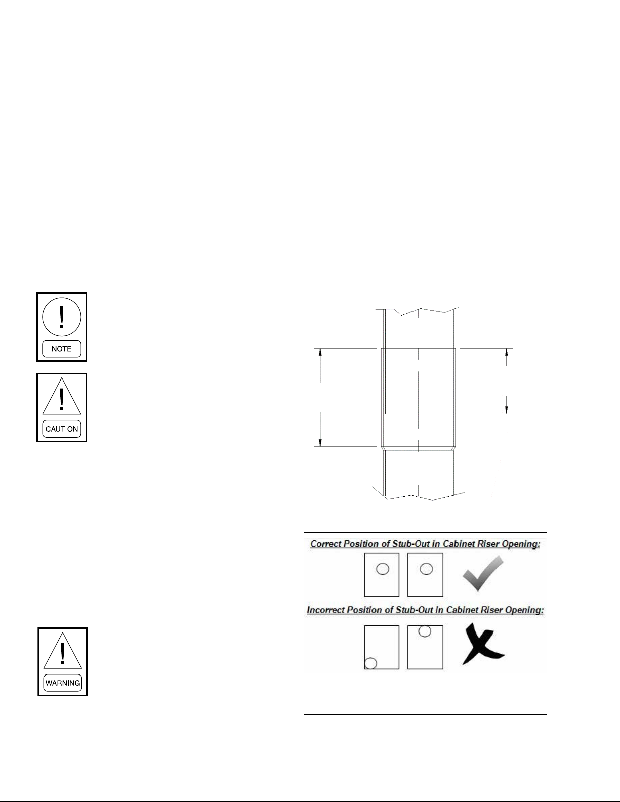
Do not allow the risers to bottom out. Riser
stub-out should be centrally located with
the stub-out opening of the cabinet riser.
Do not allow riser stub-outs or risers to
contact cabinet sheet metal.
Do not drag risers on the oor while moving the cabinet.
When the risers are shipped loose, riser installation can
be completed before cabinet installation. When installing risers, ensure the riser stub-outs are centered in the
the cabinet openings. Ensure that the risers cannot bottom out in swage (see Figure 1 on page 12).
When risers are shipped attached to cabinets, complete
the installation of risers and cabinet at the same time.
Detaching the riser from the cabinet is unnecessary.
Placing the Cabinet
The correct location of the cabinet in relation to the
floor sleeve and risers is shown in Figure 3 on page
14. To place the cabinet correctly, perform the following steps:
11
Page 12
SECTION 1 - INSTALLATION
FORM 145.18-IOM1
ISSUE DATE: 8/30/2018
1. Place the cabinet in a horizontal position on the
oor adjacent to its installation location (when risers are attached to cabinet).
The units are designed to accommodate a maximum supply and return riser stub-out movement
of 1-1/2 inches due to expansion and contraction
(total movement of 3 inches). If the total calculated riser expansion or contraction exceeds 1-1/2
inches, the field must provide expansion compensation.
2. Install eld or factory-provided riser extensions,
if required, to the unit-mounted risers prior to
moving the cabinet into nal position.
3. Raise the cabinet upright. Lower the risers through
the oor cutout, aligning the risers into the swaged
section of the unit on the oor below.
Take extra care not to scrape or dent risers during positioning. The riser tailpiece
should insert approximately 2 inches into
the 3-inch long swaged section of the unit
below.
7. Center the risers’ horizontal stub-outs (complete
with factory-installed shut-off valves) in the cabinet slot openings. Ensure that the stub-outs are
perpendicular to the side/back panel.
8. Verify all risers are vertical and that they penetrate
the swaged joint at least 1 inch.
Factory provided risers come with a 3-inch deep
swage. Do not allow risers to completely bottom
out at 3 inches in the swage. The 3-inch swage
depth is oversized to allow for adjustments if necessary to keep riser stub-outs and valves centered
in the cabinet opening.
9. Center the riser stub-out in cabinet opening to
allow for expansion and contraction. Riser stubouts must not contact on any sheet metal opening.
Otherwise damage can occur to stub-outs, resulting in water leaks and property damage.
Top Vertical
Riser
DO NOT allow the riser tailpiece to bottom
out into the swaged section. This ensures
the correct riser positioning and com-
pensates for variations in oor-to-oor
dimensions.
4. Center the risers in the pipe chase, and level the
cabinet using shims as necessary.
5. Plumb risers in two planes to assure proper unit
operation and condensate drainage.
6. Anchor the cabinets into place using rubber isolated sheet metal angles. Approved and tested
sheet metal angles are available from factory.
It is strongly recommended to install vibration
isolation pads to reduce noise transmission into
the floor. Failure to use isolation kits could result
in loud unit operation.
Do not drill or drive screws into the cabinet in the area of the internal drain pan.
2-inch Ideal
3-inch Cup
Height
Bottom
Vertical Riser
FIGURE 1 - IDEAL RISER INSERTION DEPTH
Insertion Depth
LD23535
12
LD19017
FIGURE 2 - CORRECT/INCORRECT STUB-OUT
POSITIONS IN CABINET RISER OPENING
Page 13
FORM 145.18-IOM1
ISSUE DATE: 8/30/2018
SECTION 1 - INSTALLATION
10. Braze or solder riser joints with industry accepted
solder or brazing rod material.
The riser system must be secured to building structure. Cabinets are not designed
to support the riser system.
11. Secure the riser system at a minimum of one point
to the building structure. Cabinets are not intended to support the riser system. If the temperature
range of the system exceeds the allowed expansion and contraction limits (1-1/2 inches maximum), the installing contractor must make riser
compensation provisions.
12. Ensure that individual unit shut-off valves remain
closed until the circulating loop system is cleaned
and ushed.
TABLE 1 - HIGH SERIES PHYSICAL DATA
HIGH SERIES MODEL 09 12 15 18 24 30 36
Nominal Cooling (ton)
Compressor Type Rotary Scroll
Refrigerant Charge (oz) 21 25 34 38 44 48 50
Air Coil-Type Enhanced Copper Tubes, Enhanced Aluminum Fins
Face Area (sq ft) 1.46 1.56 2.35 2.35 2.63 3.33 3.33
1
0.75 1.0 1.25 1.5 2.0 2.5 3.0
1
Rows/FPI 2/146 3/14 3/14 3/14 3/14 3/14 3/14
Water Coil-Type Enhanced Surface Co-Axial
Standard Blower/Motor
Diameter x Width (inches) 9x4T 9x4T 9x7T 9x7T 9x7 9x8 9x8
Motor HP 0.10 0.10 0.17 0.17 0.25 0.33 0.50
Hi-Static Blower/Motor DWDI Forward-Curved Centrifugal/PSC Direct Drive
Diameter x Width (inches) 9x4T 9x4T 9x7T 9x7T 10x7T 10x8T 10x8T
Motor HP 0.10 0.10 0.17 0.17 0.25 0.33 0.50
EC Motor (ECM) Blower/Motor DWDI Forward-Curved Centrifugal/ECM Direct Drive
Diameter x Width (inches) 9x4T 9x4T 9x7T 9x7T 10x7T 9x8 9x8
Motor HP 0.33 0.33 0.33 0.33 0.33 0.50 0.50
Hi-Static ECM Blower/Motor DWDI Forward-Curved Centrifugal/ECM Direct Drive
Diameter x Width (inches) 9x4T 9x4T 9x7T 9x7T 10x7T 10x8T 10x8T
Motor HP 0.33 0.33 0.33 0.33 0.33 0.50 0.50
Filter Quantity/Size (inches) 1/14x25x1 1/14x25x1 1/16x30x1 1/16x30x1 1/16x30x1 1/20x30x1 1/20x30x1
Cabinet Weight (lb)
2
Double Width Double Inlet (DWDI) Forward-Curved Centrifugal/Permanent Split Capacitor
(PSC) Direct Drive
130 130 145 145 150 175 175
Chassis Weight (lb) 70 75 95 100 140 155 160
NOTE:
1. Nominal capacity is calculated in accordance with ARI/ISO Standard 13256-1 for water loop application.
2. Cabinet weight is approximate and does not include the weight of the risers.
13
Page 14
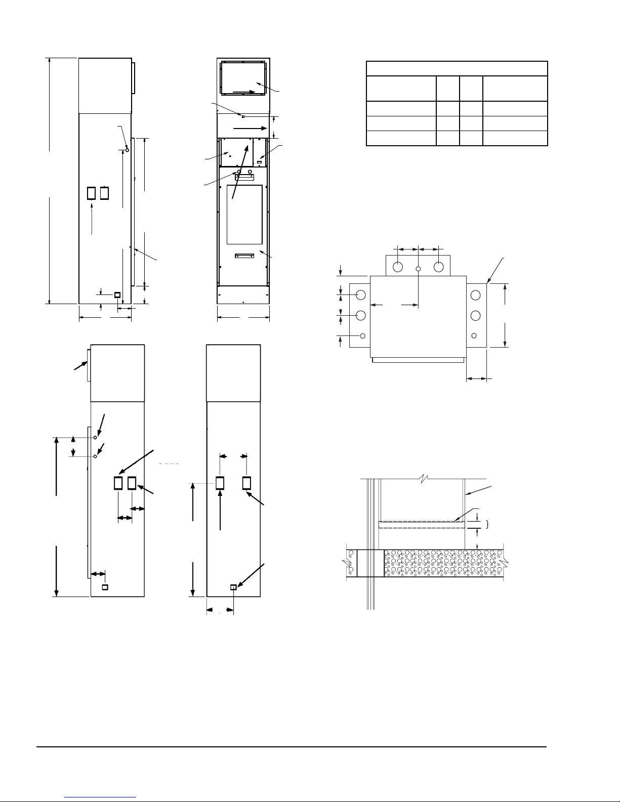
SECTION 1 - INSTALLATION
7/8-inch
Control
Entrance
80
inches
or 88
inches
Riser
Opening
KnockOuts (All
3 Sides)
3 inches
50 inches
B A
Left View
Optional 24V
Connection for
Surface Mount/
Remote Mounted
Thermostat
Electrical Box
Service
Pass-Thru
48 inches
Return Air
Flange Standard
1 inch
6 inches
4.5 inches
Hoses
Front View
Optional
Front Supply
Opening
7 inches
Switch Plate with
2 Speed Fan
Switch (Optional:
Disconnect/Fuses,
ADA Molex
Connector)
Chassis
Service
Panel
4 inches
4.25 inches
4.25 inches
4.25 inches
R
S
D
FORM 145.18-IOM1
ISSUE DATE: 8/30/2018
CABINET DIMENSIONS (INCHES)
MODEL A B
RA FLANGE
WIDTH (C)
09–18 17 17 16
15–24 20 20 19
30–36 24 24 23
Back
Optional
Riser
Cover
Shown
13.25
inches
Right
A/2
4.25 inches
R
S
D
R
S
D
1-inch
Supply
Duct
Flange
6 in.
50.5 inches
7/8-inch
OD Power
Entrance
7/8-inch
OD Control
Entrance
4.25
inches
4.5 inches
Right View
4 in.
Supply Riser
Opening
Return
Riser
Opening
inches
Supply Riser
Opening
36 inches
A/2
Back View
8.5
Return Riser
Opening
Condensate
Riser Opening
Left
Top View Front
R - Return Riser
S - Supply Riser
D - Drain Riser
4-5/16 inches
VSHP Cabinet
Drain Pan
Do not penetrate
1.50
this area with
drills or screws
4.75
NOTES
1. Supply, return, and condensate riser openings are pre-punched on all sides and eld convertible. Cut tabs to remove the knock-out.
2. Supply and return openings are 4 inches x 2.5 inches. During riser installation, ensure the stub-out is centered in supply and return openings.
3. Condensate P-trap is accessible from the front by removing the bottom cover plate.
4. Riser and shut-off location is measured from base of cabinet and does not include the stand height.
FIGURE 3 - CABINET UNIT DIMENSIONS & FLOOR SLEEVE DIMENSIONS
14
LD27627
Page 15
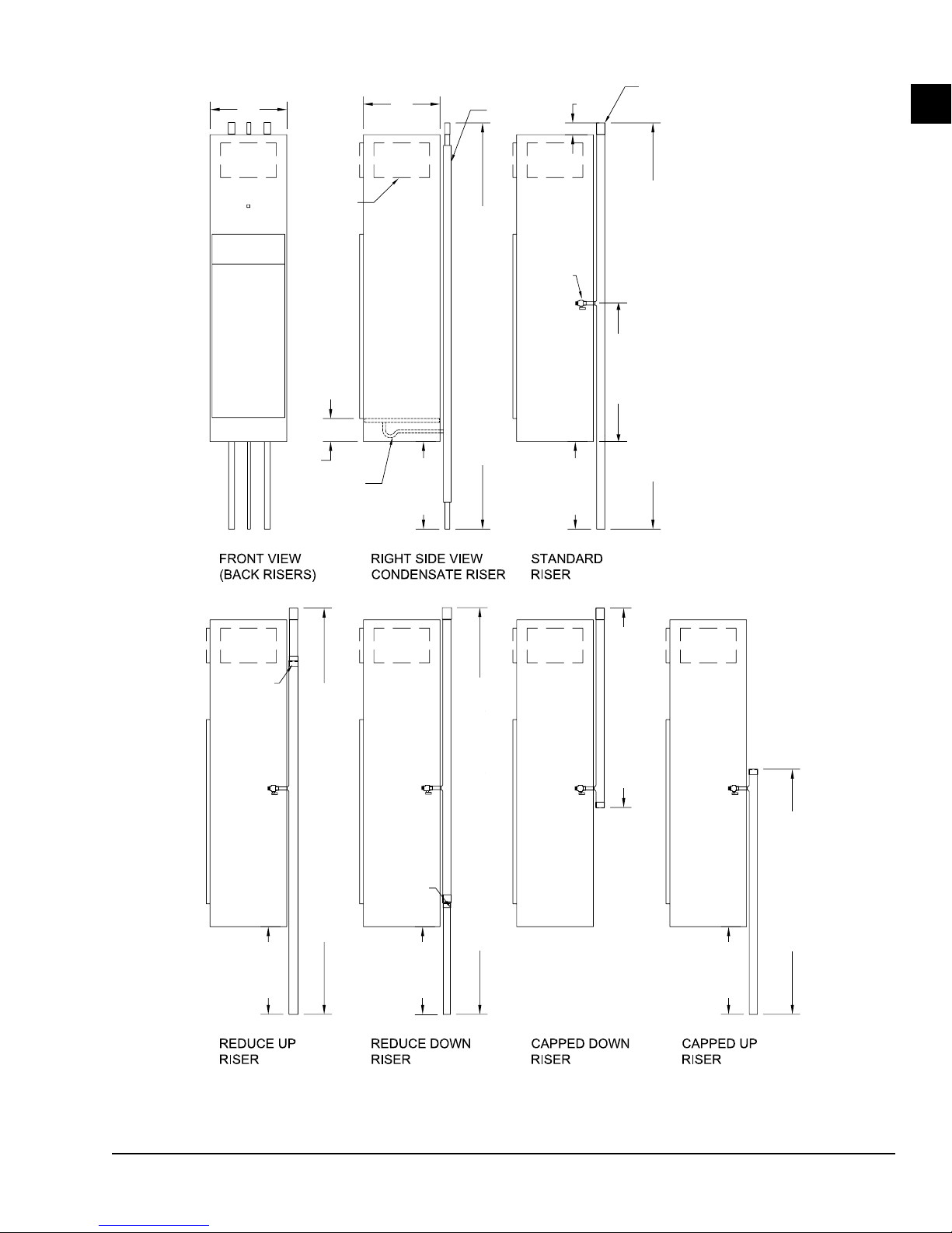
FORM 145.18-IOM1
ISSUE DATE: 8/30/2018
SECTION 1 - INSTALLATION
A
Return Air
Opening
Optional
Supply
Opening
6 in.
P-Trap
B
Insulation
Shut-Off
Ball Valve
3 in.
Supply
and
Return
Risers
Allow for 2-inch Insertion
into Swage End
1
36 inches
Condensate Riser (Max. 120 inches)
Supply and Return Riser (Max. 120 inches)
As Req'd
As Req'd
Reducer
Reducer
Reduce Up Riser (Max. 120 inches)
As Req'd
NOTE
Riser shut-off valve is measured from base of cabinet and does not include the stand height.
As Req'd
Reduce Down Riser (Max. 120 inches)
FIGURE 4 - CABINET RISER DIMENSIONS
Capped Down Riser
Capped Up Riser
As Req'd
LD19330
15
Page 16
SECTION 1 - INSTALLATION
FORM 145.18-IOM1
ISSUE DATE: 8/30/2018
RISER LOOP
5. Install the following parts at the base of each supply and return riser to enable system ushing, balancing, and servicing:
• Drain valve
• Shut-off/balancing valves
• Flow indicators
• Drain tees
6. Install strainers at the inlet of each circulating
pump.
7. Insulate loop water piping that runs through unconditioned areas of the building or outside the
building.
When the loop water temperature is maintained
between nominal operating limits of 60.0–90.0°F,
piping does not sweat or suffer undue heat loss at
conditioned space temperatures.
8. Install vents in piping loop as required to bleed
residual air from the piping system during lling
and servicing.
9. Determine the riser shut-off valves and hose kits
required for job specic site conditions:
a. Factory-supplied risers come with the appro-
priate hose kits with NPSH type fittings (see
Figure 5 on page 17). Before attaching
NPSH type hoses, check that the female end
gasket is not missing and is free of damage
or debris. See Table 2 for information on re-
placement gaskets for NPSH hose kits.
b. For field-supplied risers, it is recommended
to order the appropriate NPSH type field
hose kits from the factory, complete with
shut-off valves. Shut-off valves are to be
field sweat connected to risers (see Figure 6
on page 17).
c. Legacy chassis with NPT type connections
and matching risers with NPT shut-off valve
connections require a special hose kit. The kit
comes complete with a NPT to NPSH swivel adapter on the shut-off valve and chassis
connection to mate with factory hoses (see
Figure 7 on page 18.
TABLE 2 - REPLACEMENT HOSE GASKETS
PART NUMBER DESCRIPTION
VSGK-UFHW-050 1/2-inch Rubber Gasket
VSGK-UFHW-075 3/4-inch Rubber Gasket
HOSES
Ensure the correct hose set is matched with the compatible unit size (see Table 3). Instal the NPSH factory-
provided hoses by completing the following steps:
1. Inspect for missing or damaged hose gasket. See
Table 2 for replacement gasket part numbers.
2. Tighten by hand the screw connections to the
male NPSH tting on the shut-off valve. Hold the
ferrule stationary when tightening.
3. Tighten using a backup wrench a 1/4 turn further.
Do not overtighten.
When installing hoses, do not apply a
twist or torque load on the hose.
When tightening hoses, hold the ferrule
stationary by hand while tightening the
screw connections. Avoid tight bends, or
water ow and high pressure drops may
occur.
Hose gasket does not require extreme
tightening to obtain a seal. DO NOT
OVERTIGHTEN, or damage to gasket or
sealing surface will occur. Do not apply
thread sealant.
Hoses must be hand tightened, then further tightened for roughly another 1/4
turn. Check for leaks before tightening
any further. Do not apply excessive force;
rubber gaskets might get damaged.
Always use a back-up wrench when tightening hoses to valves. Otherwise, valve
solder joint may fail, leading to property
damage or serious injury.
TABLE 3 - CHASSIS HOSES
CHASSIS MODEL HOSE TYPE
09–18 1/2-inch NPSH Female-Female
24–36 3/4-inch NPSH Female-Female
16
Page 17

FORM 145.18-IOM1
ISSUE DATE: 8/30/2018
SECTION 1 - INSTALLATION
1
1/2-INCH OR 3/4-INCH MALE NPSH BALL VALVE
1/2-INCH OR 3/4-INCH NPSH THREADS
1/2-INCH OR 3/4-INCH FLEXIBLE CONNECTOR HOSE
(24 INCHES LONG)
GASKET
GASKET
1/2-INCH OR 3/4-INCH NPSH THREADS
1/2-INCH OR 3/4-INCH MALE NPSH
NOTE
National Pipe Straight Hose (NPSH) connection
FIGURE 5 - STANDARD FACTORY SUPPLIED NPSH HOSE KITS AND RISERS
1/2-INCH OR 3/4-INCH WATER PIPE STUB-OUT
1/2-INCH OR 3/4-INCH SWEAT TO MALE NPSH BALL VALVE
1/2-INCH OR 3/4-INCH NPSH THREADS
1/2-INCH OR 3/4-INCH FLEXIBLE CONNECTOR HOSE
(24 INCHES LONG)
1/2-INCH OR 3/4-INCH NPSH THREADS
1/2-INCH OR 3/4-INCH MALE NPSH
LD18126
FIGURE 6 - OPTIONAL FIELD SUPPLIED RISERS WITH FACTORY SUPPLIED NPSH HOSE KITS AND SHUT-
OFF VALVES
NOTE
National Pipe Straight Hose (NPSH) connection
LD18127
17
Page 18

SECTION 1 - INSTALLATION
HANDLE MUST BE
FACING THE BOTTOM
1/2-INCH OR 3/4-INCH FPT BALL VALVE
(FACTORY OR FIELD PROVIDED)
FEMALE SWIVEL
1/2-INCH OR 3/4-INCH NPSH THREADS
GASKET INCLUDED
WITH HOSE
ADAPTER MPT TO NPSH
INCLUDED WITH HOSE
GASKET INCLUDED
WITH HOSE
FORM 145.18-IOM1
ISSUE DATE: 8/30/2018
1/2-INCH OR 3/4-INCH FLEXIBLE
CONNECTOR HOSE (24 INCHES LONG)
FEMALE SWIVEL
1/2-INCH OR 3/4-INCH NPSH THREADS
ADAPTER MPT TO NPSH
INCLUDED WITH HOSE
CHASSIS WATER CONNECTION
1/2-INCH OR 3/4-INCH FPT
(FACTORY PROVIDED)
NOTE
National Pipe Straight Hose (NPSH) connection
FIGURE 7 - CONVERSION OF NPT TO NPSH TYPE FITTINGS (VB UNITS WITH NPT FITTINGS ONLY)
ELECTRICAL WIRING
Lock all electrical power supply switches
in the OFF position before installing the
Use copper conductors only! Failure
to use copper conductors can result in
equipment damage.
unit. Failure to disconnect power supply
may result in electrical shock or even
death.
Verify that the available unit power supply is compat-
Field-Installed Power Wiring
ible with the unit’s nameplate rating. Ensure the breaker is properly sized as per the nameplate. The line volt-
Power wiring to the equipment must conform to National Electrical Codes (NEC), local electrical codes,
age supply enters through the right side of the cabinet
at the 7/8-inch power entrance knock-out.
and must be performed by a licensed electrician.
Connect to the line side of the factory-installed termi-
Provide each unit with its own separate electrical circuit, means of circuit protection, and electrical disconnect switch. Follow current NEC ANSI/NFPA 70, CSA
nal block. Unit terminals are not designed to accept
other types of conductors. Failure to use copper conductors may result in equipment damage.
C22.1 C.E.C. Part 1, and state and local codes.
Failure to provide these shut-off means
could cause electrical shock or re, resulting in damage, injury, or death.
Field-Installed Low Voltage Wiring
Select a location for room thermostat, away from supply
air registers, on draft-free interior wall that is far from
lights, television, direct sunlight, or other heat sources.
LD27628
18
Locate thermostat away from supply
drafts. Ensure the back of the thermostat
is sealed and protected from air drafts.
Short cycling can result in damage to
the unit.
Page 19
FORM 145.18-IOM1
ISSUE DATE: 8/30/2018
SECTION 1 - INSTALLATION
Install the thermostat by connecting the remote thermostat wiring to microprocessor board low voltage
terminal strip. See Figure 8 for typical wiring connections.
Ensure that the control wiring between the thermostat
and the unit’s terminations does not exceed 1 ohm.
Resistance in excess of 1 ohm may cause
component damage due to insufcient AC
voltage supply.
Check all loads and conductors for
grounds, shorts, or miswiring. Do not run
the low voltage wiring in the same conduit
with the high voltage power wiring.
TABLE 4 - TYPICAL WIRE CONNECTIONS
RECOMMENDED WIRE
SIZE (GAUGE)
20 50
18 75
16 125
MAXIMUM LOW VOLTAGE
WIRE LENGTH (FEET)
Optional Surface Mount Thermostat
Connection Wiring
For applications where the thermostat is mounted directly above the return air (RA) panel, select cabinet
control option P (for example, VB12P). The thermostat
Molex pigtail harness (shipped loose) is field wired to
thermostat terminals. The Molex connector clips to the
panel-mounted, mating Molex connector on unit cabinet that is located 7 inches above the electrical box. See
optional 24V surface mount connection in Figure 3 on
page 14.
Optional Remote Mounted Thermostat Wiring
For units ordered with an extended thermostat harness
option, the thermostat is remote mounted. A specific,
plenum rated extended harness length can be ordered.
Use low voltage 7/8-inch knock-out on the side of the
unit at the electrical box to field wire the low voltage
thermostat wiring. Using a plastic bushing to pass the
harness inside electrical box to the factory wired mating Molex harness (see Figure 9). The thermostat pigtail Molex harness ships loose for field wiring to the
thermostat terminals.
1
FIGURE 8 - FIELD WIRING DIAGRAM
LD27629 LD27630
FIGURE 9 - REMOTE THERMOSTAT WIRING
LD19520
19
Page 20
SECTION 1 - INSTALLATION
Optional Disconnect
FORM 145.18-IOM1
ISSUE DATE: 8/30/2018
CLOSET AND DRYWALL INSTALLATION
To avoid potential vibration and noise issues, the RA panel should not contact any
part of the unit cabinet or sleeve. Maintain
a sufcient gap between RA panel frame
and cabinet.
Optional ADA Molex
Connection
LD27631
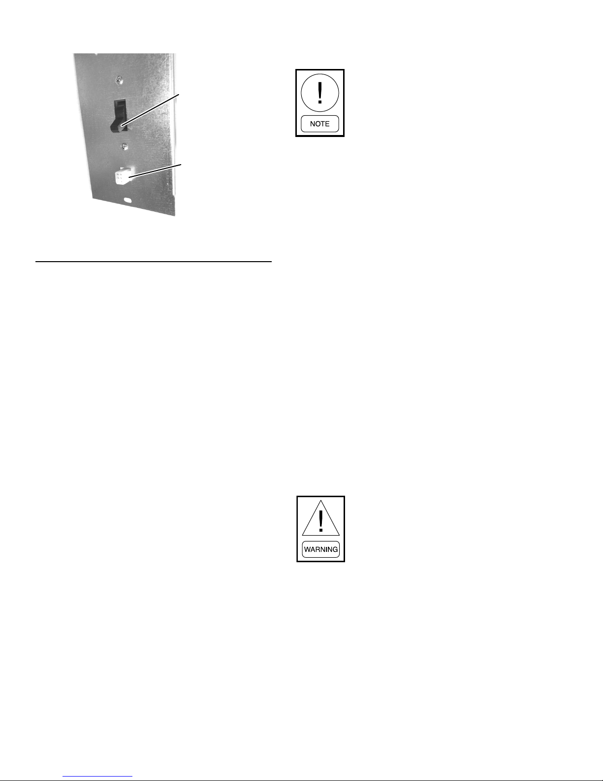
FIGURE 10 - UNIT SWITCH PLATE WITH ADA
THERMOSTAT CONNECTION
Optional ADA Door Mounted Thermostat
For units ordered with the Americans with Disabilities
Act (ADA) thermostat option to meet ADA requirements, the thermostat is located on the RA panel door
at a height of 48 inches from the base of the cabinet.
Unit is supplied with a custom RA door panel with
thermostat mounting holes, unit switch plate with a
Molex connector, and an ADA Molex pigtail harness.
See Acoustic Return Air (RA) Panel on page 20 and
Figure 14 on page 23.
Wire leads from the ADA thermostat harness are field
wired to thermostat terminals. The Molex end of the
ADA thermostat harness is field connected to the surface mounted Molex connector at unit switch plate.
Mount the thermostat using the factory provided 1/4inch number 8 screws. The ADA thermostat harness is
plenum rated. It hangs behind the RA door. For chassis
servicing, unclip harness from unit switch plate.
EC Motor (ECM) Continuous Fan
This option features a factory wired continuous low
speed fan circuit. Because of the five available motor
speed taps, the EC motor (ECM) offers an ideal range
for supporting continuous low speed fan.
Build a closet enclosure for the cabinet that incorporates the RA panel size while maintaining a sufficient
gap between the closet and cabinet. This prevents the
cabinet from contacting the RA panel and closet enclosure. Refer to Acoustic Return Air (RA) Panel on page
20, Figure 11 on page 21, and Figure 12 on page
22.
1. Cover the supply and return openings with plastic or cardboard before installing drywall around
cabinet. This prevents dust or debris from entering
the unit components.
2. Install the drywall using conventional construction methods. Do not fasten studs or drywall directly to the cabinet surface. Space the framing
members according to the RA access and the type/
quantity of supply air (SA) outlets. See Figure 11
on page 21 and Figure 12 on page 22.
3. Install sheetrock around unit cabinet by securing
the drywall to the building construction studs.
4. Cut holes around the SA and RA openings to allow access to the unit chassis, unit controls, and
the SA connection.
5. Vacuum all dust and construction debris from the
unit drain pan, electrical box, and discharge plenum after cutting out the supply/returns openings.
To prevent electrical shorts and drain pan
leaks, DO NOT penetrate unit components when driving screws near the unit
control box or drain pan. Do not allow
screws or nails to penetrate chassis, risers,
electrical junction boxes, conduits, or to
interfere with chassis removal.
ACOUSTIC RETURN AIR (RA) PANEL
The fan runs continuously on the low fan speed setting
even if there is no demand for cooling or heating. The
continuous fan is controlled by a dry contact to provide
interlocking to energy recovery ventilator (ERV) or
room occupancy control. See Figure 28 on page 46
for electrical schematics.
20
RA panels are painted standard appliance white. Carefully unpack RA panels from their shipping box. RA
panels with optional key locks require the key locks
to be field installed to the slot in the panel door. ADA
RA door panels come with an opening and pilot holes
mounting a thermostat. The ADA harness for wiring
the thermostat and connecting to the unit is shipped
loose with the thermostats.
Page 21
FORM 145.18-IOM1
ISSUE DATE: 8/30/2018
SECTION 1 - INSTALLATION
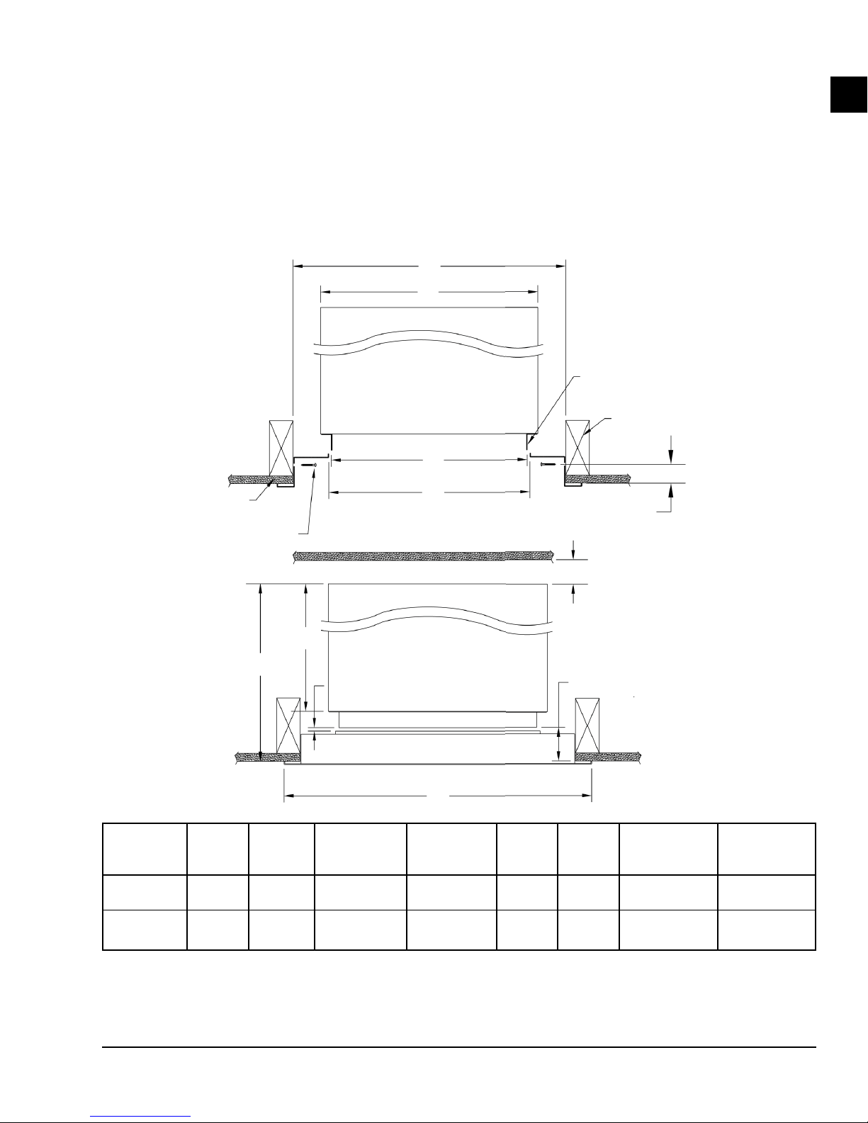
1. Locate the drywall opening at a distance from
the unit so that it prevents the RA panel from
contacting the unit sleeve. See Figure 11 on page
21 and Figure 12 on page 22.
2. Center the RA panel throat opening to the unit
cabinet RA ange opening.
3. Fasten the RA panel to frame opening using the
screws provided. See Figure 11 on page 21.
D
E
Vertical Stack Cabinet
Top View
B
0.5-inch Drywall
6 x Fasteners
C
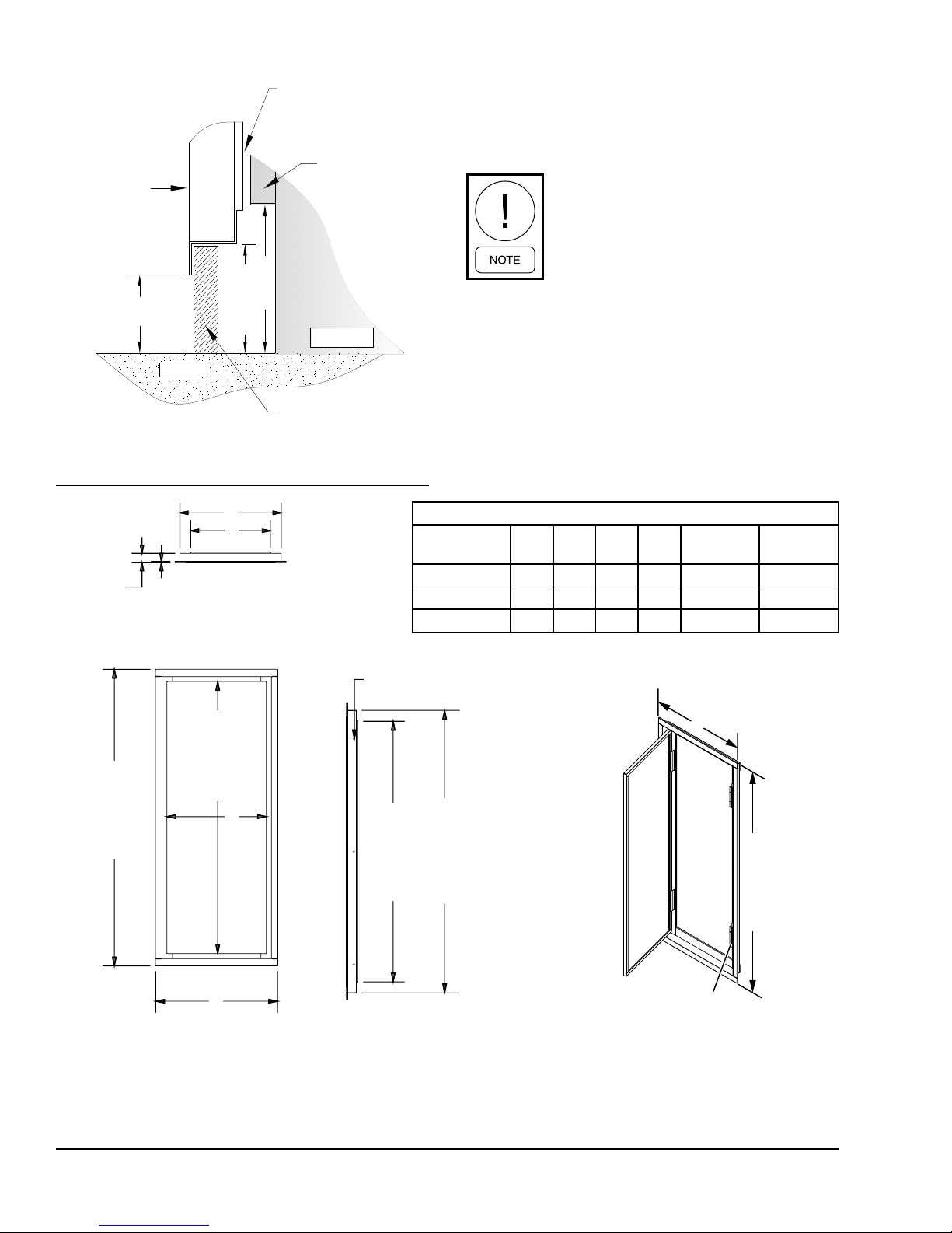
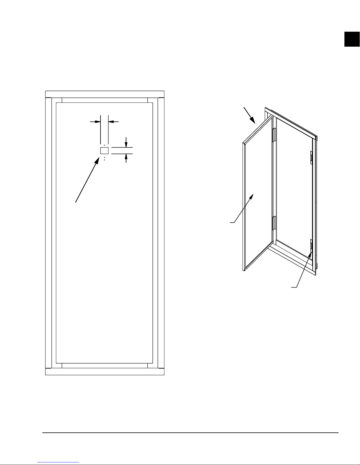
Figure 14 on page 23 shows the opening for mounting an ADA compliant thermostat at 48 inches above
floor. Note that location of the opening on the door
changes if the cabinet is ordered with a stand. A left
hand opening door is shown. The RA panel with ADA
is not reversible. It must be ordered in either a left or
right-hand opening configuration, determined by the
location of the door hinge.
Return Air Flange
Standard = 1 inch
Optional OA Fresh Air = 4.25 inches
Wall Stud
1-3/16 inch
(Drywall to Fastener
Based on 0.5-inch Drywall
1
F
Vertical Stack Cabinet Top View
G
Min. 1/8-inch, Max. 3/8-inch Gap
(RA Flange Must Not Contact
Acoustic Door Frame)
A
UNIT
SIZE
09/12/15/18 25 3/4 19 19 1/4 23 3/4 ± 1/8 20 20
24/30/36 29 3/4 23 23 1/4 27 3/4 ± 1/8 24 24
NOTE
All dimensions are in inches.
A
(PANEL
WIDTH)
B
(SLEEVE
WIDTH)
C
(R/A PANEL
OPENING)
D
(ROUGH IN
WIDTH)
E
(UNIT
WIDTH)
DEPTH)
H
Rear Closet to Cabinet Back:
No Risers = 0.5-inch Minimum
With Risers = 5-inch Minimum
2.25-inch Minimum
(Unit Sleeve to Drywall)
F
(UNIT
G
(NO OA
OPTION)
23 1/4 MIN
23 1/2 MAX
27 1/4 MIN
27 1/2 MAX
G
(OA OPTION)
27 1/4 MIN
27 1/2 MAX
31 1/4 MIN
31 1/2 MAX
FIGURE 11 - CRITICAL RETURN AIR (RA) PANEL WITH UNIT CABINET INSTALLATION DIMENSIONS
LD19500
21
Page 22
SECTION 1 - INSTALLATION
FORM 145.18-IOM1
ISSUE DATE: 8/30/2018
RA flange must not
contact door frame
Acoustical
1-inch RA flange
Panel Door
Frame
2.5 inches
6 inches
3.75 inches
Cabinet
Floor
Closet Drywall
FIGURE 12 - RA PANEL CROSS SECTION
INSTALLATION AT FLOOR LEVEL
B
B
C
C
1.92
1.92
0.28
0.28 inches
inches
Figure 12 on page 22 shows a cutaway view for a
standard cabinet with no stand. Add the stand height to
the cabinet to obtain the correct dimension of the RA
panel from floor.
For maximum return airow, the ush
mounted acoustic panel must be centered
vertically and horizontally over the RA
opening of the cabinet. SA duct collar
extensions may be required to prevent
short cycling.
LD27621
ALL DIMENSIONS ARE IN INCHES
MODEL A B C D
VSCS09–12 22.75 20.50 16.25 18.50 20.75 52.75
VSCS15–24 25.75 23.50 19.25 21.50 23.75 52.75
VSCS30–36 29.75 27.50 23.25 25.50 27.75 52.75
ROUGH-IN
WIDTH
ROUGH-IN
HEIGHT
Mounting Holes x 6
Mounting Holes x 6
52.50
50.5 inches
56.75
54.75 inches
D
D
50.25
54.50
(54 3/4" ROUGH-IN
48.25 inches
52.5 inches
WALL OPENING)
(52.75-inch Rough-In Wall Opening)
A
A
NOTES:
1. Acoustic panel is powder coated in appliance white
2. Acoustic panel can be installed on the right hand side or left hand side.
3. See Figure 11 on page 21 for additional RA panel and cabinet installation information.
FIGURE 13 - RA PANEL DIMENSIONS
A
Magnetic Catches x 2
Magnetic
Catches x 2
54.75 inches
LD19319C
22
Page 23
FORM 145.18-IOM1
ISSUE DATE: 8/30/2018
1.5 inches
1.50
1.25 inches
1.25
Left Hand Opening Shown
LEFT HAND OPENING SHOWN
SECTION 1 - INSTALLATION
1
Thermostat mounting location,
Thermostat mounting location,
Cut-out for routing
cut-out for routing ADA thermostat
ADA thermostat harness
harness
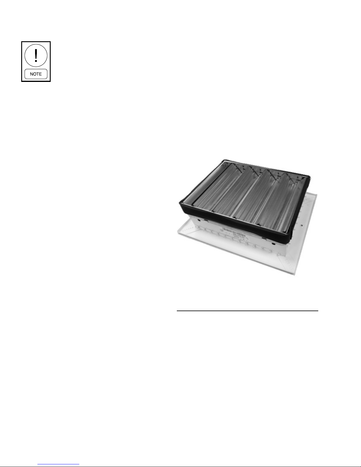
0.5-inch Insulation
1/2" Insulation
Magnetic Catches x 2
Magnetic Catches x 2
Notes:
- Powder coated in 'Appliance White'
NOTES:
- Inside panel lined with 1/2" acoustical insulation
1. Powder coated in appliance white
- Hinged panel complete with magnetic latches
2. Inside panel lined with 0.5-inch acoustical insulation
- Panel comes either Left or Right hand opening
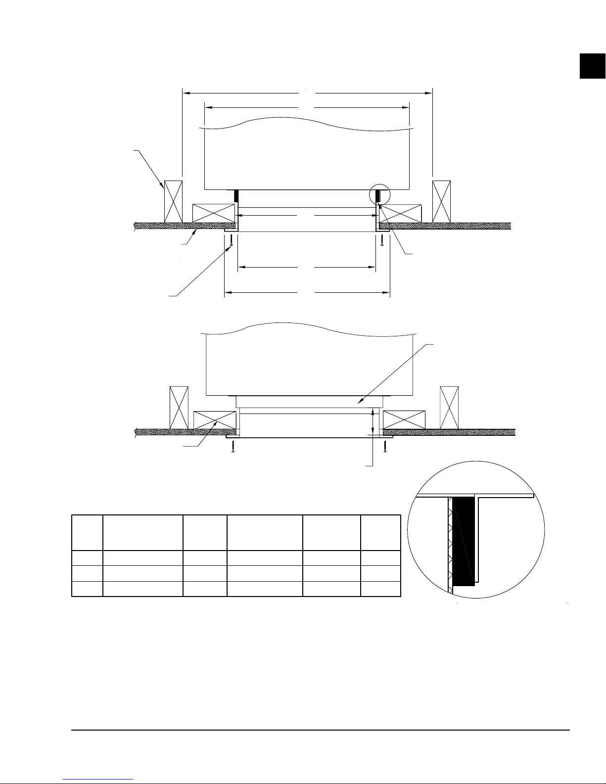
3. Hinged panel complete with magnetic latches
4. Panel comes either left or right hand opening
LD19320
FIGURE 14 - OPTIONAL RA PANEL WITH ADA MOUNTED THERMOSTAT
LD19320
23
Page 24
SECTION 1 - INSTALLATION
FORM 145.18-IOM1
ISSUE DATE: 8/30/2018
SUPPLY AIR (SA) DUCTWORK
Ensure there is no direct contact between
cabinet sheet metal parts and drywall en-
closure. This includes RA and SA anges.
Failure to follow these instructions will
negatively affect unit sound performance.
Horizontal Supply Air
A 2-inch duct flange (field provided) may be required
to eliminate supply air recirculation when shallow profile, single deflection supply grilles are installed at the
cabinet discharge openings. If the discharge from the
cabinet is not ducted completely into the conditioned
space, air can recirculate into the RA opening from the
space inside the drywall enclosure.
Manufacturer supplied grilles have a clearance of a 1/4
inch around the perimeter to fit inside the unit supply
flange. Other grille manufacturers could have different
clearances that should be verified.
Field supplied gasket must be applied in order to prevent air recirculation and vibration transfer when supply grilles are mounted to unit supply opening. When
mounting supply grilles with optional volume damper
directly to cabinet supply flange, the volume damper
fits inside the cabinet supply flange. It is recommended
to apply 1/8-inch neoprene tape (field supplied) around
the perimeter of the volume damper prior to inserting
it into the supply opening. See Figure 15 on page 24
for an example. This assists in reducing noise transmission and air recirculation into the unit closet.
For ducted openings, connect the unit supply opening
to the supply ductwork using a watertight flexible duct
connector. This minimizes the transmission of operating sounds through the supply ductwork. Elbows with
turning vanes or splitters are recommended to minimize air noise due to turbulence and to help reduce
static pressure.
Top Discharge Supply Air
Units that are installed with a top discharge should be
connected to the supply ductwork with a watertight
flexible connector. This minimizes the transmission
of operating sounds through the supply ductwork. Elbows with turning vanes or splitters are recommended
to minimize air noise due to turbulence and to help reduce static pressure.
For information on available unit horizontal and top
supply openings see Table 5 and Table 6 on page 26.
Recommended face velocity at the outlet supply grille
is 300–500 FPM. Table 6 gives face velocity at the unit
supply openings in relation to Table 5. To calculate the
face velocity at the supply grille, take the FPM from
Table 6 and divide by the supply grille area factor.
LD27622
FIGURE 15 - SUPPLY GRILLE WITH VOLUME
DAMPER AND 1/8-INCH NEOPRENE TAPE
APPLIED TO PERIMETER
24
Page 25
FORM 145.18-IOM1
ISSUE DATE: 8/30/2018
WALL STUD
Wall Stud
D
E
VERTICAL STACK CABINET
Vertical Stack Cabinet
Top View
TOP VIEW
Optional Opposed Blade Damper
A
Louvered Supply Grille
Detail A
DETAIL A
SECTION 1 - INSTALLATION
1
0.5-inch Drywall
1/2”
DRYWALL
B
MOUNTING SCREWS
Mounting Screws
VERTICAL STACK CABINET
Vertical Stack Cabinet
Optional Framing Studs
for Supply Opening
FOR SUPPLY OPENING
UNIT
15–24 X B=X - 0.5 C=X + 1.75 23 3/4 ± 1/8 20
30–36 X B=X - 0.5 C=X + 1.75 27 3/4 ± 1/8 24
NOTES:
(SUPPLY GRILLE
SIZE
NOMINAL WIDTH)
9–18 X B=X - 0.5 C=X + 1.75 20 3/4 ± 1/8 17
1. All dimensions are in inches and typical for factory supplied grilles only.
2. Check dimensions for eld-supplied grilles because dimensions can be different.
OPTIONAL
FRAMING STUDS
A
B
(GRILLE
WIDTH)
(UNIT SUPPLY DUCT FLANGE
(Unit Supply Duct Flange
TO 1/2” DRYWALL FACE)
to 0.5-inch Drywall Face)
C
(GRILLE
FLANGE WIDTH)
C
Top View
TOP VIEW
2.25-inch Minimum
2-1/4” MIN.
D
(ROUGH IN
WIDTH)
(UNIT
WIDTH)
E
1/8” THICK FIELD SUPPLIED
1/8-inch Thick Field Supplied
GASKET TAPE
Gasket Tape Applied Around
APPLIED AROUND
Full Perimeter of Supply
FULL PERIMETER OF
Grilled with Volume Damper
SUPPLY GRILLE WITH
VOLUME DAMPER
FACTORY SUPPLIED
Factory Supplied
1” DUCT FLANGE
1-inch Duct Flange
DETAIL A
Detail A
FIGURE 16 - UNIT MOUNTED SUPPLY GRILLE INSTALLATION
LD19321
25
Page 26

SECTION 1 - INSTALLATION
FORM 145.18-IOM1
ISSUE DATE: 8/30/2018
TABLE 5 - UNIT SUPPLY OPENING SIZES
HORIZONTAL OPENINGS
SINGLE HORIZONTAL DOUBLE HORIZONTAL
MODEL
NO TOP
OPENING
TOP OPENING
NO TOP
OPENING
TOP OPENING
9 14W x 12H 14W x 6H 14W x 8H Not Available Not Available 12 x 8
12 14W x 14H 14W x 6H 14W x 10H Not Available Not Available 12 x 8
15 16W x 14H 14W x 6H 14W x 10H Not Available 14W x 8H 14 x 12
18 Not Available 14W x 6H 14W x 12H 14W x 6H 14W x 10H 14 x 12
24 Not Available 14W x 10H 16W x 14H 14W x 6H 14W x 10H 14 x 12
30 Not Available 14W x 6H 20W x 14H 14W x 6H 16W x 12H 18 x 16
36 Not Available 14W x 10H Not Available 14W x 6H 16W x 14H 18 x 16
NOTES:
1. Unit mounted supply grilles are supplied as double-deection type.
2. Grilles for unequal airow applications (for example, unit mounted plus ducted supply) are provided with integral opposed blade dampers.
3. All grilles are supplied in standard appliance white painted nish.
4. Grilles are shipped loose for eld installation upon completion of cabinet/ductwork/drywall installation.
5. Top opening size does not change. When combined with any other discharge arrangement, it is included in determining horizontal opening
grille size.
6. Openings marked Not Available result in face velocities outside the recommended 300–500 FPM range.
7. Hi-static blower option or single horizontal discharge openings with unit mounted supply grille are not recommended.
TRIPLE
HORIZONTAL
NO TOP
OPENING
TOP OPENING
TABLE 6 - UNIT SUPPLY FACE VELOCITY (FPM)
HORIZONTAL OPENINGS
MODEL
SINGLE HORIZONTAL DOUBLE HORIZONTAL
NO TOP
OPENING
TOP OPENING
NO TOP
OPENING
TOP OPENING
9 291 272 219 Not Available Not Available 510
12 316 344 221 Not Available Not Available 645
15 354 314 283 Not Available 236 471
18 Not Available 391 294 294 235 587
24 Not Available 397 273 364 291 729
30 Not Available 416 276 339 269 538
36 Not Available 410 Not Available 385 261 610
NOTES:
1. Tabulated face velocities do not account for supply grille free area factor. Face velocities at supply grille are higher depending on grille type.
2. Face velocities are based on the nominal rated CFM and feet per minute (FPM).
3. Face velocities are calculated by taking the average across all openings. Tabulated top opening face velocity is only for units with single
top opening and no horizontal openings.
TRIPLE
HORIZONTAL
NO TOP
OPENING
TOP OPENING
26
Page 27

FORM 145.18-IOM1
ISSUE DATE: 8/30/2018
SECTION 1 - INSTALLATION
TOP MOUNTED FRESH AIR INTAKE
The optional fresh air intake provides a 4-inch round
duct connection on top of the unit (see Figure 23 on
page 31 for right and left hand version). The fresh
air is discharged upstream of the direct expansion (DX)
coil through the discharge collector box.
Do not allow incoming air to bypass the
DX coil, otherwise, damage to the unit
may occur.
Units can be selected with the fresh air opening located
on the top left or right hand side for ease of installation.
It is recommended that applications requiring 10% or
more outdoor air utilize a pressurized fresh air system.
Unit cabinet static pressure at the RA opening is not
designed to draw 10% or more in passive fresh air systems.
The fresh air duct inside the unit is insulated to protect
the unit from condensation in the event of high humidity air. However excessively moist fresh air over prolonged periods can result in condensate inside unit or
closet.
During transportation, handling or installation of the cabinet, excessive handling
can cause an inner black plastic cover to
come loose and jam the actuator, preventing the damper from opening.
During start-up, check that the damper is opening when
the unit fan is running. It can take 20 seconds to fully
open. If the damper opens, the unit is operating as intended. If the damper fails to open, the cause is likely a
loose cover preventing actuator from rotating. Remove
the actuator to service the damper.
Removing the Actuator
1. Remove the damper plate:
a. Look underneath the top of the RA flange to
notice the damper assembly.
b. Remove the seven fasteners holding the
damper plate (see Figure 19 on page 28).
c. Drop the plate and disconnect the quick-con-
nect terminals from the harness.
2. Remove the red cover from the actuator body (see
Figure 18 on page 27).
1
To avoid condensate developing inside
ducts and equipment, it is recommended
to pretreat fresh air with a high humidity
ratio before it enters the unit assembly
through ERVs or make-up air units.
The unit comes with a 4-1/4 inch RA sleeve. Front
supply openings come with a 4-1/4 inch supply plaster
flange.
Top Mounted Fresh Air Intake with Motorized
Damper
This include the same features as the top mounted fresh
air intake option with the addition of a motorized damper assembly inside the discharge collector box similar
(see Figure 23 on page 31).
The damper assembly can be easily removed for servicing (see Removing the Actuator on page 27). The
motorized damper assembly opens during FAN ON operation. See Figure 28 on page 46 for the electrical
schematic. For other control options, please contact the
factory.
LD23557
FIGURE 17 - DAMPER PLATE FASTENERS
LD23558
FIGURE 18 - REMOVE THE RED COVER
27
Page 28

SECTION 1 - INSTALLATION
LD23559
FORM 145.18-IOM1
ISSUE DATE: 8/30/2018
SYSTEM FLUSHING AND CLEANING
After the piping system is complete, and before connecting the refrigeration chassis, flush and clean the
risers This ensures a proper start-up and continued efficient operation of the system (see Figure 20 on page
29).
Flushing the System
1. Ensure the supply and return riser shut-off valves
are closed at each unit.
2. Using exible hoses or piping, connect the supply
and return stub-outs in the unit located at the end
of the riser run(s).
If the building has more than ten floors, connect
the supply and return stub-outs in the last two
units to divide the water flow and reduce pressure
drop at the pump (see Figure 20 on page 29).
LD23560
FIGURE 19 - POSITION BLACK COVER
3. If the black cover is loose, position it in place and
slide it back onto the actuator (see Figure 19 on
page 28).
4. Secure the red cover back over the actuator assembly.
5. Ensure the plastic tabs are secured to the metal
body bracket.
6. Connect the quick-connect terminals, and insert
the damper assembly into the discharge collector
box.
7. Fasten the assembly using the seven fasteners.
3. Open the shut-off valves in the units that have had
the supply and return risers interconnected.
4. Fill the water circulation system with clean water from the make-up water supply. Ensure the air
vents are open during initial lling. Do not allow
the system to overow.
5. Close the air vents, and start the circulating pump.
6. Ensure that all air is bled from the system by
cracking each air vent.
Make-up water must be available in sufcient volume to replace the volume occupied by the air that is bled off.
7. When all the air is vented and the water is circulating under pressure, check the entire system for
leaks. Repair any leaks as required.
8. Raise the temperature to approximately 85.0°F
by setting the loop temperature controls. Visually
check for any leaks that may have occurred due to
the increased heat. Repair any leaks as required.
9. Open the drain at the lowest point in the system.
The make-up water ow rate must be
equal to the rate of the drain bleed.
28
Page 29

FORM 145.18-IOM1
to chassis
Hose or piping
Riser
Return
Riser
ISSUE DATE: 8/30/2018
SECTION 1 - INSTALLATION
10. Continue to bleed the system until the water leaving the drain is clear, no less than 2 hours.
11. Completely drain the piping system.
Cleaning the System
1. After the initial ushing, chemically clean the
system. Repeat the method in Flushing the System
on page 28 to rell the system and circulate the
cleaning solution.
It is recommended to use the services of a professional water treatment company for the type of
solution to be used and the duration of the cleaning application.
2. Once the cleaning process is complete, shut off
the circulating pump and completely drain the
system.
3. Rell the system with clean water to prepare for
refrigeration chassis connection and system startup.
It is recommended that a professional water treatment company perform ongoing
maintenance of the water loop including
chemical analysis and ushing, if necessary. The water loop testing should be performed at intervals recommended by the
professional water treatment consultant.
Stub-outs to
Stub-outs
chassis
Hose or piping
connecting
supply & return
connecting supply
runouts
and return runouts
1
It is recommended that the water loop
testing be performed at least once a year.
Standard practice is once a month or
quarterly.
The customer is responsible for completing adequate water loop maintenance
over the lifespan of the units. Otherwise,
damage to the units may occur.
Supply
Supply
Riser
Return
Riser
LD19685
FIGURE 20 - SYSTEM FLUSHING AND CLEANING
29
Page 30

SECTION 1 - INSTALLATION
CABINET DIMENSIONS (INCHES)
MODEL A B C
09–12 17 8 12
15–24 20 12 14
30–36 24 16 18
1. Optional fresh air option comes with 2.5-inch RA ange.
2. Optional front supply opening comes with 2.5-inch duct ange.
3. All other openings come with standard 1-inch duct ange.
4. Left and right hand versions shown.
A
4-inch Ø Fresh Air
Take-Off Intake
A
Left Hand Shown
(Right Hand Opposite Side)
FORM 145.18-IOM1
ISSUE DATE: 8/30/2018
Front Supply Flange
(Optional)
Fresh Air Discharge
Collector Box
2.5-inch Return Air
Flange
C
2.5 inches
Front Supply
(Optional)
Optional 24V
Molex Connection
for Surface Mount/
Remote Mounted
Thermostat
Unit Switch
Plate
B
3 inches
Ø 7/8-inch
Power
Entrance
Ø 7/8-inch
Control
Entrance
(Knock-Out,
Both Sides)
Riser Opening
Knock-Outs
(All Three Sides)
FIGURE 21 - FRESH AIR OPENING WITHOUT MOTORIZED DAMPER – LEFT AND RIGHT HAND UNIT SHOWN
30
LD27632
Page 31

FORM 145.18-IOM1
ISSUE DATE: 8/30/2018
SECTION 1 - INSTALLATION
CABINET DIMENSIONS (INCHES)
MODEL A B C
09–12 17 8 12
15–24 20 12 14
30–36 24 16 18
1. Optional fresh air option comes with 4.25-inch RA ange.
2. Optional front supply opening comes with 4.25-inch duct ange.
3. All other openings come with standard 1-inch duct ange.
4. Left and right hand versions shown.
A
4-inch Ø Left Hand Fresh Air
Take-Off Intake
Optional Front Supply
(4.25-inch Flange)
Fresh Air Discharge
Collector Box
4.25-inch Return Air
Flange
4-inch Ø Fresh Air
Take-Off Intake
1
4.25 inches
A
C
C
B
Optional Front
Supply
(4.25-in. Flange)
Fresh Air
Discharge
Collector Box
Optional 24V
Molex Connection
for Surface Mount/
Remote Mounted
Thermostat
Unit Switch
Plate
3 inches
Ø 7/8-inch
Power
Entrance
Ø 7/8-inch
Control
Entrance
(Knock-Out,
Both Sides)
Riser
Opening
61-7/8 inches
Knock-Outs
(All Three
Sides)
FIGURE 22 - FRESH AIR OPENING WITH MOTORIZED DAMPER – LEFT AND RIGHT HAND UNIT SHOWN
LD27634
31
Page 32

SECTION 1 - INSTALLATION
FORM 145.18-IOM1
ISSUE DATE: 8/30/2018
CHASSIS INSTALLATION
Prior to installation of the refrigeration
chassis and connection to the supply and
return risers, the entire water loop system
must be ushed and cleaned. See System
Flushing and Cleaning on page 28.
Do not apply sealing tape or pipe dope on
NPSH style ttings.
Check that the female end gasket from the
hose is not missing, has no visible damage,
and is free of debris.
Always use a backup wrench when installing hoses.
Remove the inner service panel from the cabinet, and
inspect the interior compartment for debris. Clear all
debris and vacuum construction dust from the cabinet.
Locate the supply and return shut-off valves. Verify the
following:
• The valves are closed.
• The type of hose kit ttings provided with the
unit. Units shipped after June 2013 feature NPSH
ttings (straight thread), while previous generation hose kits are NPT type (tapered thread). Refer
to Riser Loop on page 16 for more information.
For Units with NPSH Valve Connection and
Hose Sets
NPSH flexible connection hoses do not require any
pipe dope or sealant tape. DO NOT ADD THREAD
SEALANT OR PIPE DOPE TO NPSH FITTINGS.
Connect the hoses to the NPSH fitting on the shut-off
valves. Always use a backup wrench when tightening
the hose to the valve fitting. Allow the hoses to hang
free inside the cabinet.
Protect the chassis from physical damage, drywall dust, paint fumes, and any
other construction contamination during
installation.
Hoses must be hand tightened then further tightened no more than 1/4 turn. Do
not apply excessive force.
Always use a backup wrench when tightening hoses to valves. Otherwise, damage
to the valve solder joint can lead to property damage or serious injury.
Slide the chassis into place using the following steps:
1. Attach the NPSH hoses to the NPSHttings on the
chassis stub-outs by projecting through the top of
the compressor compartment access cover.
2. Use a backup wrench to prevent twisting of the
copper water piping within the chassis assembly.
3. For chassis installation, see For Units with NPT
Style (Tapered Pipe Thread) Valve Connection
and Hoses on page 32 .
For Units with NPT Style (Tapered Pipe
Thread) Valve Connection and Hoses
Factory supplied NPT flexible connection hoses come
with thread sealing compound pre-applied. NO ADDITIONAL THREAD SEALING TAPE SHOULD
BE REQUIRED. Connect the hoses to the female pip
thread fitting on the shut-off valves. Always use a
backup wrench when tightening the hose to the valve
fitting. Allow the hoses to hang free inside the cabinet.
Slide chassis into place using the following steps. A
J-swivel adapter (supplied with the hose kit) comes
with thread sealing compound pre-applied. NO ADDITIONAL THREAD SEALANT SHOULD BE REQUIRED.
32
Page 33
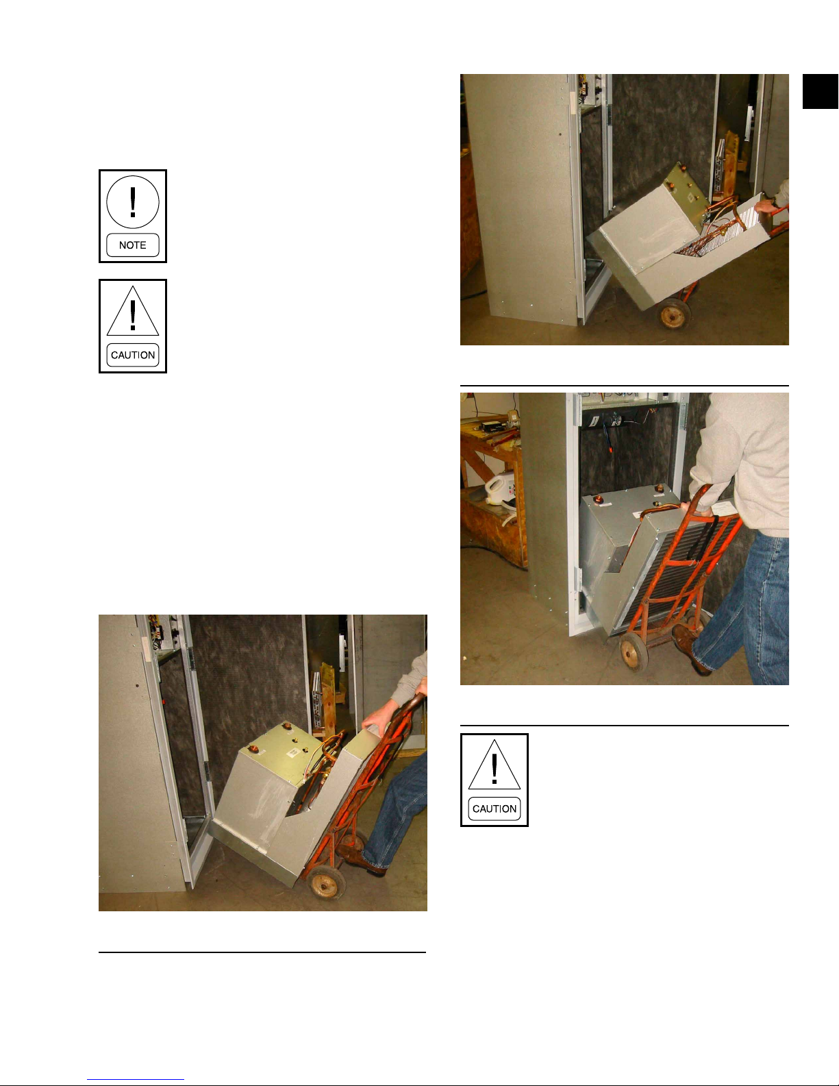
FORM 145.18-IOM1
ISSUE DATE: 8/30/2018
SECTION 1 - INSTALLATION
1. Thread the swivel adapters into the female pipe
thread ttings projecting through the top of the
compressor compartment access cover. To prevent
twisting of the copper water piping in the chassis
assembly, always use a backup wrench.
To minimize the possibility of damage to
the chassis or cabinet and for maximum
ease of installation, the use of a twowheeled dolly is strongly recommended.
Do not contact the nned coil face. Damage to the ns will result.
2. Lift chassis from the front of chassis (see Figure
22 on page 33).
3. Align chassis with the opening of the cabinet. Tilt
the chassis sufciently for the base of the chassis
to clear the mounting rails on the cabinet drain
pan (see Figure 23 on page 33).
1
LD23565
FIGURE 24 - TILT THE CHASSIS
4. Insert the chassis midway into the opening of the
cabinet. Lower the rear of the chassis until the
base of the chassis touches the formed mounting
rails in the cabinet drain pan (see Figure 24 on
page 33).
LD23564
FIGURE 23 - LIFT THE CHASSIS FRONT
LD23566
FIGURE 25 - INSERT THE CHASSIS
Before fully inserting chassis, ensure
wiring harness and or water hoses will
not be pinched.
5. Pivot the chassis base on the front edge of the
drain pan rails. Before fully inserting the chassis,
ensure the wiring harness and water hoses cannot
be pinched between the chassis and cabinet (see
Figure 25 on page 34).
33
Page 34
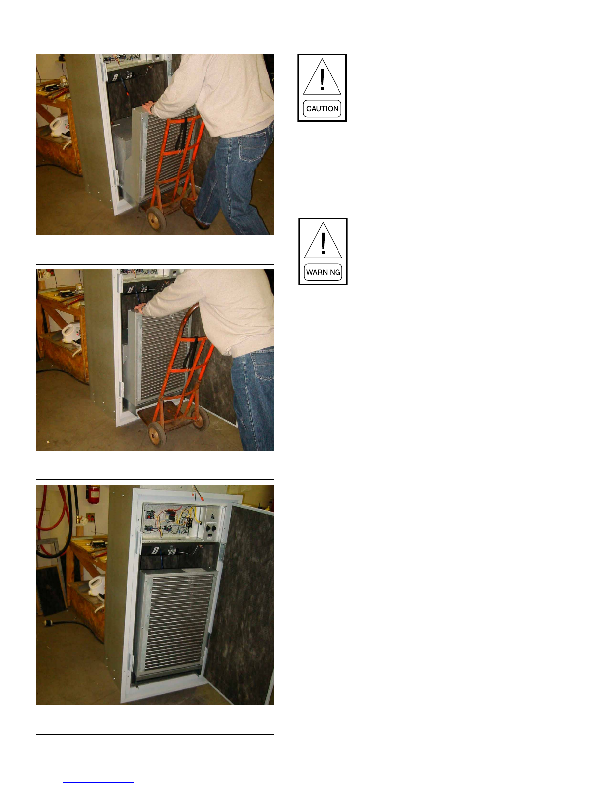
SECTION 1 - INSTALLATION
FIGURE 26 - PIVOT THE CHASSIS
LD23567
FORM 145.18-IOM1
ISSUE DATE: 8/30/2018
Do not apply excessive force when sliding
chassis into cabinet.
6. Slide the chassis into the cabinet until at least 3/4
of the depth of the chassis is supported. The chassis should slide easily on the drain pan rails. DO
NOT APPLY EXCESSIVE FORCE. Ensure that
the chassis will not tip forward before removing
dolly (see Figure 26 on page 34).
To avoid damage from clogged coil surfaces, plugged motor ventilation openings, and potential unit failure, DO NOT
operate unit without compete enclosure,
supply grille, RA panel, and lter in place.
7. Connect the hoses to the chassis. Ensure that the
hoses cannot be pinched once the chassis is slid
into place.
FIGURE 27 - SLIDE THE CHASSIS
8. Without touching the anges on either side, ensure the chassis' alignment in the cabinet is centered in the cabinet opening (see Figure 27 on
page 34).
9. Complete the electrical connections to the chassis using the two quick-connect mating plugs. The
unit-mounted plug ends are located on the bottom
of the control box.
LD23568
10. Remove the shipping cover from the face of the
air-to-refrigerant coil.
11. Install the inner service panel and check that the
foam gasket seal between the panel and the chassis is slightly compressed.
If necessary, pull the chassis forward slightly to
ensure an adequate seal between the chassis and
the service panel.
12. Install the air lter onto the face of the service
panel. Slide the lter upward into the top-retaining clip until the bottom of the lter can be
dropped onto the lower clip.
FIGURE 28 - CHECK THE CHASSIS
34
LD23569
13. Install service panel.
14. Install the RA panel into the drywall opening if
not already installed. Refer to Acoustic Return Air
(RA) Panel on page 20. Secure the panel into
the drywall with six screws.
Page 35

FORM 145.18-IOM1
ISSUE DATE: 8/30/2018
SECTION 2 - OPERATION
Once the installation is complete and the system is
cleaned and flushed, begin unit start-up. Open the supply and return shut-off valves at each unit, refill the
system, and bleed off all air.
PRE-START-UP CHECKLIST
Before energizing the unit, perform the following
checks and complete the Vertical Stacked Heat Pump
Start-Up and Performance Checklist (Form 145.18-
CL1) in compliance with warranty requirements.
The high voltage power supply is correct and in
accordance with the nameplate ratings.
The field wiring and circuit protection are the cor-
rect size.
The unit is electrically grounded.
The low voltage control wiring is correct per the
unit wiring diagram.
There is vibration isolation (for example, unit iso-
lation pad, flexible hoses).
The low-side or high-side pressure temperature
caps are secure and in place.
All the unit access panels are secure and in place.
The thermostat is in the OFF position.
INITIAL UNIT START-UP
During installation, testing, servicing,
and troubleshooting of this product, it
may be necessary to work with live electrical components. Failure to follow all electrical safety precautions when exposed to
live electrical components could result in
serious injury or death.
1. Close the disconnect switches on all units to provide line power.
2. Set the thermostat to the highest temperature setting.
3. Set the thermostat system switch to COOL and
the fan control switch to AUTO. The compressor
should NOT run.
4. Reduce the temperature control setting until the
compressor and supply fan energize, with the
following results:
• Water temperature leaving the heat exchanger is warmer than the entering water temperature (EWT) (approximately 9.0–12.0°F).
• The blower operation is smooth.
• The compressor and blower amps are within
the nameplate data values.
2
The water flow is established and circulating
through all the units.
The ductwork (if required) is correctly sized, run,
taped, and insulated.
The indoor blower turns freely without rubbing.
If applicable, glycol fluid was added in the proper
mix to prevent freezing in closed system application.
Clean, properly sized air filters are in place.
The condensate drain pipe is firmly secured to
both the drain riser and the drain pan stub.
• The suction line is cool with no frost observed in the refrigerant circuit.
5. Turn the thermostat switch to the OFF position.
The compressor and fan stop running and the reversing valve de-energizes.
6. To allow for pressure equalization, leave the unit
off for approximately 5 minutes.
7. Turn the thermostat to the lowest setting.
8. Set the thermostat system switch to the HEAT position. The compressor should NOT run.
9. Adjust the temperature setting upward until the
compressor and supply fan energize, with the following results after several minutes:
• Warm air is detected at the supply register.
• The water temperature decreases approximately 5.0–9.0°F across the heat exchanger.
35
Page 36
SECTION 2 - OPERATION
FORM 145.18-IOM1
ISSUE DATE: 8/30/2018
• The blower and compressor operation are
smooth with no frost observed in the refrigerant circuit.
10. Set the thermostat to maintain the desired space
temperature.
11. Check all water connections for any leaks, including condensate drain hose connections.
SYSTEM LOOP TEMPERATURE
Loop temperatures affect unit performance, power
consumption (efficiency), maintenance and reliability,
and noise levels. High EWT in cooling mode above
rated conditions of 86.0°F EWT increases power consumption and compressor noise levels. Sustained operation above 100°F EWT can increase maintenance
costs, and increased compressor noise can affect occupancy comfort. The unit is designed to operate up to
110.0°F EWT for intermittent periods when high load
conditions elevate system loop temperatures.
It is not recommended to set system loop temperatures
at 110.0°F in case high load conditions cause supply
loop temperatures to exceed 110.0°F EWT. Unit sound
performance can be negatively impacted at high EWT.
During heating season, the maximum operating loop
temperature is 90.0°F EWT. For optimal unit performance, it is recommended to maintain system loop
temperatures at or above the rated conditions of 68.0°F
EWT. If system loop temperatures are low and freezing
the coaxial is possible, the system loop must contain a
glycol fluid mixture that is adequate to prevent freezing. The minimum loop temperature with glycol mixture is 20.0°F EWT. Lower loop temperatures result in
lower efficiency and heating capacity.
High system loop temperatures may nega-
tively affect unit performance, efciency,
maintenance and reliability, and noise
levels.
FAN SPEED ADJUSTMENT
Multi-speed direct drive motors are used in all units as
standard. Permanent split capacitor (PSC) fan motors
have a minimum of three selectable speeds. EC motors
(ECMs) have five speeds, however only two speeds are
recommended and available for selection.
Optional ECMs increase operating efficiency by consuming fewer watts than standard PSC motors. Motors
are factory programmed and cannot be re-programmed
in the field. Each motor contains five low voltage speed
taps. Two speed taps are used as standard.
Blower speed taps are factory set for optimum heating
and cooling airflow ranges. See Table 8 on page 37
for factory blower speed settings and minimum operating airflow.
Operating the unit below the minimum
airow may result poor heating/cooling
performance and periodic unit lockout.
A unit mounted two-speed fan switch located on the
electrical box cover allows the fan speed to switch
from LOW and HIGH. This enables the fan speed to
meet site conditions such as increased ductwork static
pressure or the use of higher efficient filters.
Perform a test run on the installed system to ensure operation with sufficient heating and cooling airflow. Excessive ductwork static pressure results in an improper
volume of airflow. High airflow volumes result in elevated noise levels and can affect occupancy comfort.
Lock all electrical power supply switches
in the OFF position before servicing the
unit. Failure to disconnect power supply
may result in electrical shock or even
death.
TABLE 7 - OPERATING LIMITS
COOLING HEATING
MINIMUM EWT 30.0°F 20.0°F
MAXIMUM EWT 110.0°F 90.0°F
36
Page 37
FORM 145.18-IOM1
ISSUE DATE: 8/30/2018
SECTION 2 - OPERATION
2
EXTERNAL STATIC PRESSURE (IN W.G.)
MIN.
RATED
MOTOR
0.0 0.05 0.1 0.15 0.2 0.25 0.3 0.35 0.4 0.45 0.5
340 330 320 310 300 285 270 255 240 225 -
CFM
CFM
HIGH
SPEED
340 220
LOW 255 250 240 230 220 210 - - - - -
445 435 425 415 400 385 370 355 340 320 295
430 290
LOW 350 345 335 325 315 305 290 - - - -
HIGH
580 570 560 550 535 520 505 485 465 445 425
550 335
LOW 385 380 375 370 365 355 345 335 - - -
HIGH
700 690 675 660 635 615 595 575 550 525 495
685 430
LOW 450 445 440 435 430 425 - - - - -
HIGH
880 855 835 815 795 770 740 710 680 650 615
850 575
HIGH
LOW 715 710 705 690 670 650 630 605 580 - -
1115 1100 1075 1050 1020 990 960 930 895 850 800
1075 700
LOW 965 960 950 935 915 895 870 840 810 780 745
HIGH
1230 1200 1170 1140 111 0 1075 1040 1000 960 915 870
1220 840
LOW 1115 1100 1075 1050 1020 990 960 930 895 855 805
HIGH
EXTERNAL STATIC PRESSURE (IN W.G.)
MIN.
CFM
CFM
RATED
SPEED
MOTOR
0.0 0.05 0.1 0.15 0.2 0.25 0.3 0.35 0.4 0.45 0.5 0.55 0.6 0.65 0.7 0.75 0.8
375 370 360 350 340 330 315 300 285 265 245 220 - - - - -
340 220
HIGH
LOW 330 320 310 300 290 280 270 255 240 225 - - - - - - -
485 475 465 455 440 425 410 395 380 360 340 315 - - - - -
430 290
HIGH
665 650 635 615 595 575 555 540 520 500 475 450 420 395 370 340 -
750 735 715 695 675 655 630 605 580 555 525 495 465 435 - - -
990 970 950 930 910 890 865 845 820 795 770 740 710 680 650 615 575
1180 1170 1160 1145 1130 111 0 1090 1070 1050 1025 1000 970 940 910 875 840 800
1340 1320 1295 1270 1245 1220 1190 1160 1130 1100 1070 1040 1010 980 945 910 870
550 335
685 430
850 575
1075 700
1220 840
LOW 390 385 380 370 360 350 335 320 305 - - - - - - - -
LOW 580 570 560 550 535 520 505 485 465 445 425 400 375 350 - - -
LOW 670 655 640 625 605 585 560 535 510 485 460 435 - - - - -
LOW 795 785 775 760 745 730 715 695 675 655 630 605 580 - - - -
LOW 985 980 975 970 960 950 940 935 920 905 895 875 850 825 795 765 730
HIGH
HIGH
HIGH
HIGH
HIGH
LOW 1180 1170 1160 1145 1130 111 0 1090 1070 1050 1025 1000 970 940 910 875 840 800
12
09
SIZE
UNIT
TABLE 8 - PSC STANDARD BLOWER PERFORMANCE (CFM)
15
18
24
30
36
09
12
15
SIZE
UNIT
TABLE 9 - PSC HIGH STATIC BLOWER PERFORMANCE (CFM)
18
24
30
36
37
Page 38
SECTION 2 - OPERATION
FORM 145.18-IOM1
ISSUE DATE: 8/30/2018
EXTERNAL STATIC PRESSURE (IN W.G.)
MIN.
RATED
MOTOR
0.0 0.05 0.1 0.15 0.2 0.25 0.3 0.35 0.4 0.45 0.5
342 317 292 276 259 247 236 228 220 214 207
CFM
340 220
CFM
HIGH
SPEED
EXTERNAL STATIC PRESSURE (IN W.G.)
463 431 399 378 356 340 324 317 310 299 289
600 567 534 500 466 445 424 396 367 340 312
760 726 693 667 642 615 587 574 561 529 497
891 863 835 809 784 757 730 689 648 601 554
1131 1105 1079 1058 1037 1016 994 972 949 934 918
1265 1235 1206 1184 1163 1141 111 8 1085 1051 1008 965
430 290
550 335
685 430
850 575
1075 700
1220 840
LOW 278 252 226 212 198 189 180 - - - -
LOW 342 317 292 276 259 247 236 - - - -
LOW 495 447 399 372 346 307 268 - - - -
LOW 600 567 534 500 466 445 424 396 - - -
LOW 760 726 693 667 642 615 587 574 - - -
LOW 918 894 870 852 835 808 781 762 743 718 -
HIGH
HIGH
HIGH
HIGH
HIGH
HIGH
LOW 1065 1037 1009 987 965 949 934 910 886 874 861
0.0 0.05 0.1 0.15 0.2 0.25 0.3 0.35 0.4 0.45 0.5 0.55 0.6 0.65 0.7 0.75
MIN.
CFM
CFM
RATED
SPEED
MOTOR
411 382 354 334 315 300 286 279 272 263 254 242 231 220 - -
340 220
LOW 342 317 292 276 259 247 236 228 220 - - - - - - -
HIGH
554 529 504 477 451 430 408 393 378 360 341 330 319 300 - -
430 290
LOW 463 431 399 378 356 340 324 317 310 299 290 - - - - -
HIGH
659 623 587 564 541 5 11 482 462 441 419 397 372 346 320 - -
550 335
HIGH
891 863 835 809 784 757 730 689 648 601 554 518 482 446 408 -
1002 971 940 912 883 854 826 800 774 749 724 698 671 643 615 586
1265 1235 1206 1184 1163 1141 1118 1085 1051 1008 965 913 861 808 756 701
1462 1418 1375 1331 1287 1241 1194 1153 111 2 1053 994 964 934 903 872 840
685 430
850 575
1075 700
1220 840
LOW 600 567 534 500 466 445 424 396 367 340 312 - - - - -
LOW 760 726 693 667 642 615 587 574 561 529 497 469 441 412 - -
LOW 866 827 789 762 735 708 682 659 636 612 587 571 - - - -
LOW 1065 1037 1009 987 965 949 934 910 886 874 861 839 818 - - -
HIGH
HIGH
HIGH
HIGH
LOW 1265 1235 1206 1184 1163 1141 1118 1085 1051 1008 965 913 861 - - -
09
12
15
SIZE
UNIT
TABLE 10 - ECM STANDARD BLOWER PERFORMANCE (CFM)
18
38
24
30
36
09
12
15
18
SIZE
UNIT
TABLE 11 - ECM HIGH STATIC BLOWER PERFORMANCE (CFM)
24
30
36
Page 39

FORM 145.18-IOM1
ISSUE DATE: 8/30/2018
SECTION 2 - OPERATION
2
EXTERNAL STATIC PRESSURE (IN W.G.)
MIN.
RATED
MOTOR
0.0 0.05 0.1 0.15 0.2 0.25 0.3 0.35 0.4 0.45 0.5 0.55 0.6 0.65 0.7 0.75
278 252 226 212 198 189 180 - - - - - - - - -
CFM
CFM
1
SPEED
278 252 226 212 198 189 180 - - - - - - - - -
340 180
2 342 317 292 276 259 247 236 228 220 214 207 - - - - -
3 411 382 354 334 315 300 286 279 272 263 254 242 231 220 - -
4 463 431 399 378 356 340 324 317 310 299 290 - - - - -
5 554 529 504 477 451 430 408 393 378 360 341 330 319 300 - -121
430 236
2 342 317 292 276 259 247 236 - - - - - - - - -
3 411 382 354 334 315 300 286 279 272 263 254 242 231 220 - -
495 447 399 372 346 307 268 - - - - - - - - -
550 268
4 463 431 399 378 356 340 324 317 310 299 289 - - - - -
5 554 529 504 477 451 430 408 393 378 360 341 330 319 300 - -151
2 600 567 534 500 466 445 424 396 367 340 312 - - - - -
3 659 623 587 564 541 511 482 462 441 419 397 372 346 320 - -
495 447 399 372 346 307 268 - - - - - - - - -
685 396
4 760 726 693 667 642 615 587 574 561 529 497 469 441 412 - -
5 891 863 835 809 784 757 730 689 648 601 554 518 482 446 408 -181
2 600 567 534 500 466 445 424 396 367 340 312 - - - - -
3 659 623 587 564 541 511 482 462 441 419 397 372 346 320 - -
659 623 587 564 541 511 482 462 441 419 397 372 346 320 - -
850 574
4 760 726 693 667 642 615 587 574 561 529 497 469 441 412 - -
5 891 863 835 809 784 757 730 689 648 601 554 518 482 446 408 -241
2 760 726 693 667 642 615 587 574 - - - - - - - -
3 866 827 789 762 735 708 682 659 636 612 587 571 - - - -
918 894 870 852 835 808 781 762 743 718 - - - - - -
1075 718
4 891 863 835 809 784 757 730 689 648 601 554 - - - - -
5 1002 971 940 912 883 854 826 800 774 749 724 698 671 643 615 586301
2 1065 1037 1009 987 965 949 934 910 886 874 861 - - - - -
3 1131 1105 1079 1058 1037 1016 994 972 949 934 918 - - - - -
4 1265 1235 1206 1184 1163 1141 1118 1085 1051 1008 965 913 861 808 756 701
5 1462 1418 1375 1331 1287 1241 1194 1153 1112 1053 994 964 934 903 872 840361
918 894 870 852 835 808 781 762 743 718 - - - - - -
1220 861
2 1065 1037 1009 987 965 949 934 910 886 874 861 - - - - -
3 1131 1105 1079 1058 1037 1016 994 972 949 934 918 - - - - -
4 1265 1235 1206 1184 1163 1141 1118 1085 1051 1008 965 913 861 808 756 701
5 1462 1418 1375 1331 1287 1241 1194 1153 1112 1053 994 964 934 903 872 840
SIZE
UNIT
TABLE 12 - ECM BLOWER PERFORMANCE - ALL SPEED TAPS (CFM)
09
1. All airow ratings are at lowest voltage rating of dual rating (for example, 208 volt).
2. Airow ratings include resistance of wet coil and clean air lters.
NOTES
39
Page 40

SECTION 2 - OPERATION
FORM 145.18-IOM1
ISSUE DATE: 8/30/2018
UNIT CONTROLS
The control system microprocessor board is specifically designed for water source heat pump operation.
The control system interfaces with a conventional type
thermostat.
• The unit is complete with a self-contained lowvoltage control circuit.
• The unit incorporates a lockout circuit that provides reset capability from a hard lockout at the
space thermostat or base unit if any of the following standard safety devices trip and shut off the
compressor:
• Low pressure limit switch (loss of charge)
• High pressure limit switch
• Freeze protection switch (unit shutdown on
low water temperature)
• Condensate overflow switch
• The unit operates with conventional thermostat
designs and has a low voltage terminal strip for
easy hook-up.
• Unit control board has on-board diagnostics and
fault code display.
• Standard controls include anti-short cycle and low
voltage protection.
• The control board monitors each refrigerant safety switch independently.
• The control board has a random start feature.
• The control board retains the last ve fault codes
in nonvolatile memory that cannot be lost in the
event of a power loss.
Sequence of Operation
The room thermostat makes a circuit between R and
Y1 for cooling.
The call passes to the unit microprocessor control that
determines whether the requested operation is available and if so, which components to energize.
If at any time there is a call for both heating and cooling, the heating operation is performed. Heating always
takes priority. If cooling mode is operating, it halts and
ends the call for cooling.
Continuous Blower
With the room thermostat fan switch set to AUTO and
the system switch set to either AUTO or HEAT, the
blower energizes whenever a cooling or heating operation is requested. The blower energizes after any specified delay associated with the operation.
The indoor blower energizes for a minimum runtime of
30 seconds. Additionally, the indoor blower delays for
10 seconds between operations.
When the room thermostat calls for cooling, the lowvoltage control circuit completes from R to Y1 and G.
The compressor and fan motor energize. After completing the specified fan on delay for cooling, the microprocessor control energizes the blower motor.
Once the room thermostat has been satisfied, it deenergizes Y1. If the compressor satisfies its minimum
runtime, the compressor and fan de-energize. Otherwise, the unit operates the cooling system until the
minimum runtime for the compressor completes. After
the compressor de-energizes and the fan off delay for
cooling elapses, the blower stops.
To be available, a compressor must not be locked-out
because of a high pressure limit switch, low pressure
limit switch, condensate overflow switch, or a freezestat trip. The anti-short cycle delay (ASCD) must elapse.
Safety Control Reset
All VPCS heat pumps are furnished with a high pressure limit switch, a low pressure limit switch, low water temperature freeze protection switch, and condensate overflow switch to prevent compressor operation
during abnormal conditions.
If any of these safety devices activate, a lockout relay
circuit engages. The circuit interrupts heating and cooling operation even if the control contacts automatically
re-close.
For heating, the room thermostat makes a circuit between R and W1. The microprocessor control energizes the compressor and fan, enabling the unit to run in
heating mode.
40
This microprocessor driven lockout circuit must be
manually reset. Reset by momentarily moving the thermostat control (system) switch to OFF, then back to
HEAT or COOL (or AUTO).
The lockout circuit can also be reset by opening and
closing the unit mounted disconnect switch.
Page 41

FORM 145.18-IOM1
ISSUE DATE: 8/30/2018
SECTION 2 - OPERATION
If the unit must be reset more than twice
on consecutive operating cycles, check
the unit for a dirty lter, abnormal EWT,
inadequate or excessive water ow, or
refrigerant circuit malfunction. If the
unit continues to cutout, contact a trained
service technician.
Operation Errors
Each refrigerant system is monitored for operation outside of the intended parameters. Errors are handled as
described below. All system errors override minimum
runtimes for compressors.
High Pressure Limit Switch
If a high pressure limit switch opens, the microprocessor control de-energizes the compressor, initiates the
ASCD, and stops the unit fans (soft lockout). If a call
for cooling or heating is still present at the conclusion
of the ASCD, the microprocessor control re-energizes
the compressor and unit fan.
If a high pressure limit switch opens three times within
2 hours of operation, the microprocessor control permanently locks out the system compressor, requiring a
manual reset of the system (a hard lockout). To manually reset, either de-energize the 24-volt power to the
unit or turn the room thermostat to OFF, then back to
either HEAT or COOL as required. The microprocessor control flashes a fault code indicating the high pressure lockout (see Table 13 on page 42).
Low Pressure Limit Switch
The microprocessor does not monitor the low pressure
limit switch during the initial 30 seconds of compressor
operation. For the following 30 seconds, the microprocessor control monitors the low pressure limit switch
to ensure it closes. If the low pressure limit switch fails
to close after the 30 second monitoring phase, the microprocessor control de-energizes the compressor, initiates the ASCD, and stops the fan (a soft lockout).
If a low pressure limit switch opens three times within
1 hour of operation, the microprocessor control board
locks out the compressor (a hard lockout) and flashes a
fault code (see Table 13 on page 42).
Freeze-Stat
If a freeze-stat opens, the microprocessor control deenergizes the compressor and initiates the ASCD. If
a call for cooling or heating is still present after the
ASCD, the microprocessor control re-energizes the
halted compressor.
Condensate Overow Switch
A condensate overflow fault occurs if the condensate
overflow switch opens continuously for 30 seconds.
The compressor shuts down regardless of the minimum runtime, and alarm 15 sets. The fan continues
operating in its current state.
The microprocessor control logs the first incident per
compressor request. Lockout occurs on the second fault
occurrence within a request cycle, requiring reset or
power cycling. If the compressor request is removed,
the fault occurrence counter resets to zero. When lockouts are removed, the alarm resets.
Safety Controls
The microprocessor control monitors the following inputs:
1. A suction line freeze-stat to protect against low
leaving water temperatures (LWTs) (opens at
34.0°F and resets at 48.0°F).
2. A high pressure limit switch to protect against excessive discharge pressures (opens at 600 psig ±
25 psig).
3. A low pressure limit switch to protect against loss
of refrigerant charge (opens at 55 psig ± 5 psig).
4. A condensate overow switch to protect against
condensate overow.
2
Once the low pressure limit switch is proven (closes
during the 30 second monitor period), the microprocessor control monitors the low pressure limit switch for
any openings. If the low pressure limit switch opens
for more than 5 seconds, the microprocessor control
de-energizes the compressor, initiates the ASCD, and
stops the compressor (a soft lockout).
If the call for cooling is still present after the ASCD,
the microprocessor control re-energizes the compressor.
Coaxial Freeze Protection Setpoint
The field can select the coaxial freeze protection
setpoint. The unit uses a suction line freeze-stat factory
setpoint for compressor lockout when the LWT drops
below 35.0°F (resets at 48.0°F). To lower the setpoint
for low temperature heating applications with an adequate water-antifreeze solution, unplug the freezestat sensor located at P6 on the microprocessor control
board, and plug in the (pink) jumper attached to the
existing harness.
41
Page 42

SECTION 2 - OPERATION
FORM 145.18-IOM1
ISSUE DATE: 8/30/2018
Installing the jumper bypasses the freeze-stat, enabling
heating operation with a leaving glycol fluid mixture
temperature below 35.0°F. Use the jumper only in low
water applications with adequate antifreeze protection,
otherwise damage can occur.
Random Start
The random start function upon power up imposes
time delay of 4 minutes plus a random delay of 1–64
seconds. A combination of the following determine the
random number generator seed:
• A xed seed programmed at the factory
• The serial number
• The model number
• The hours of the unit's compressor runtime
Compressor Protection
In addition to the external pressure switches, the compressor also has inherent internal protection. If there
is an abnormal temperature rise in a compressor, the
protector opens to shut down the compressor. The microprocessor control incorporates features to minimize
compressor wear and damage. The control uses an
ASCD to prevent compressor operation too soon after its previous run. Additionally, a minimum runtime
is imposed any time a compressor is energized. The
ASCD initiates on unit start-up and on any compressor
reset or lockout.
Microprocessor Control Unit Flash Codes
The microprocessor control uses various flash codes
to aid in troubleshooting. The flash codes are distinguished by a short on and off cycle (approximately
200ms on and 200ms off).
During normal operation, to show that the microprocessor correctly functions, the control boards flash for
1 second on, 1 second off, also known as a heart beat.
Do not confuse this with an error flash code. To prevent confusion, a 1-flash fault code is not used. For a
list of all flash codes, see Table 13 on page 42.
Last Error
When this button is pressed and released one time
within 5 seconds, it flashes the last five fault codes on
the board’s LED. The most recent alarm is shown first
and the oldest alarm is shown last.
Test Reset
When this button is pressed and released one time
within 5 seconds, any ASCD is bypassed for one cycle.
Comm Setup
If the board is to be networked with other units, this
button is used to set the network address.
The first time the button is pressed within 5 seconds, it
scans the bus, assigns itself the first available address
(starts at 2), and then flashes that address once.
Pressing the button two times within 5 seconds causes
the control to flash the address.
TABLE 13 - FLASH CODES
FLASH CODES DESCRIPTION
On Steady Control failure – replace control
Heart Beat Normal operation
2 Flashes Control waiting on ASCD
3 Flashes HPS1 - Compressor lockout
5 Flashes LPS1 - Compressor lockout
13 Flashes Compressor held off due to low voltage
14 Flashes
15 Flashes
16 Flashes
NOTES
1. These ash codes do not represent alarms.
EEPROM storage failure (control
failure)
Condensate overow switch -
compressor lockout
Coaxial freeze thermostat compressor lockout
1
1
Communication
The communication protocol is Modbus™ using the
RTU method of packet framing at 19200-baud rate.
Current alarms or active restrictions are flashed on the
microprocessor control LED.
42
Page 43

FORM 145.18-IOM1
ISSUE DATE: 8/30/2018
SECTION 3 - MAINTENANCE
Unit maintenance is simplified by the following preventive suggestions:
1. At least once a month, visually inspect the unit.
Pay special attention to hose assemblies. Note any
signs of hose deterioration or cracking. Immediately attend to any sign of minor leakage.
2. At least once every three months, perform lter
maintenance to ensure proper operation of the
equipment. Inspect the lters and replace when
visible dirt buildup is evident.
To avoid fouled machinery and extensive
unit clean up, DO NOT operate units
without lters in place or use the unit as a
temporary cooling/heating source during
construction.
3. Every three months, inspect the condensate drain
pan for algae growth and mineral buildup. Excessive algae or mineral deposits in the drain pan or
drain line can result in condensate overow and
unpleasant mildew odors.
4. Annually check the fan motor and blower assembly. All units employ permanently lubricated fan
motors. DO NOT OIL FAN MOTORS. Vacuum
any accumulation of dirt from the motor ventilation slots and the blower wheel.
5. Annually check the contactors and relays within
the control panel. Inspect the panel for any signs
of damage caused by overheated contacts or temperature change to the wiring. Check the terminals for tightness.
6. Annually conduct an amperage check on the compressor and fan motor. An amperage draw more
than 10% higher than the nameplate values can
indicate heat exchanger fouling, low water ow,
or premature physical motor failure.
7. At least once a year, inspect the air-to-refrigerant heat exchanger surface. A dirty or partially
clogged coil can signicantly reduce operating capacity and can result in serious equipment
problems. If the coils appear dirty, clean them using mild detergent or a commercial coil-cleaning
agent.
3
8. Inspect hoses, valves, and connections for water
leaks. For hose connection leaks, inspect rubber
hose gaskets and replace them as required.
43
Page 44

SECTION 3 - MAINTENANCE
FORM 145.18-IOM1
ISSUE DATE: 8/30/2018
THIS PAGE INTENTIONALLY LEFT BLANK.
44
Page 45

FORM 145.18-IOM1
ISSUE DATE: 8/30/2018
APPENDIX
FIGURE 29 - PSC MOTOR WIRING DIAGRAM
LD23571
45
Page 46

APPENDIX
FORM 145.18-IOM1
ISSUE DATE: 8/30/2018
FIGURE 30 - ECM WIRING DIAGRAM
46
LD23572
Page 47

FORM 145.18-IOM1
ISSUE DATE: 8/30/2018
APPENDIX
FIGURE 31 - CONTINUOUS FAN WITH ECM WIRING DIAGRAM
LD27633
47
Page 48

APPENDIX
FORM 145.18-IOM1
ISSUE DATE: 8/30/2018
FIGURE 32 - MOTORIZED DAMPER ECM WIRING DIAGRAM
48
LD23574
Page 49
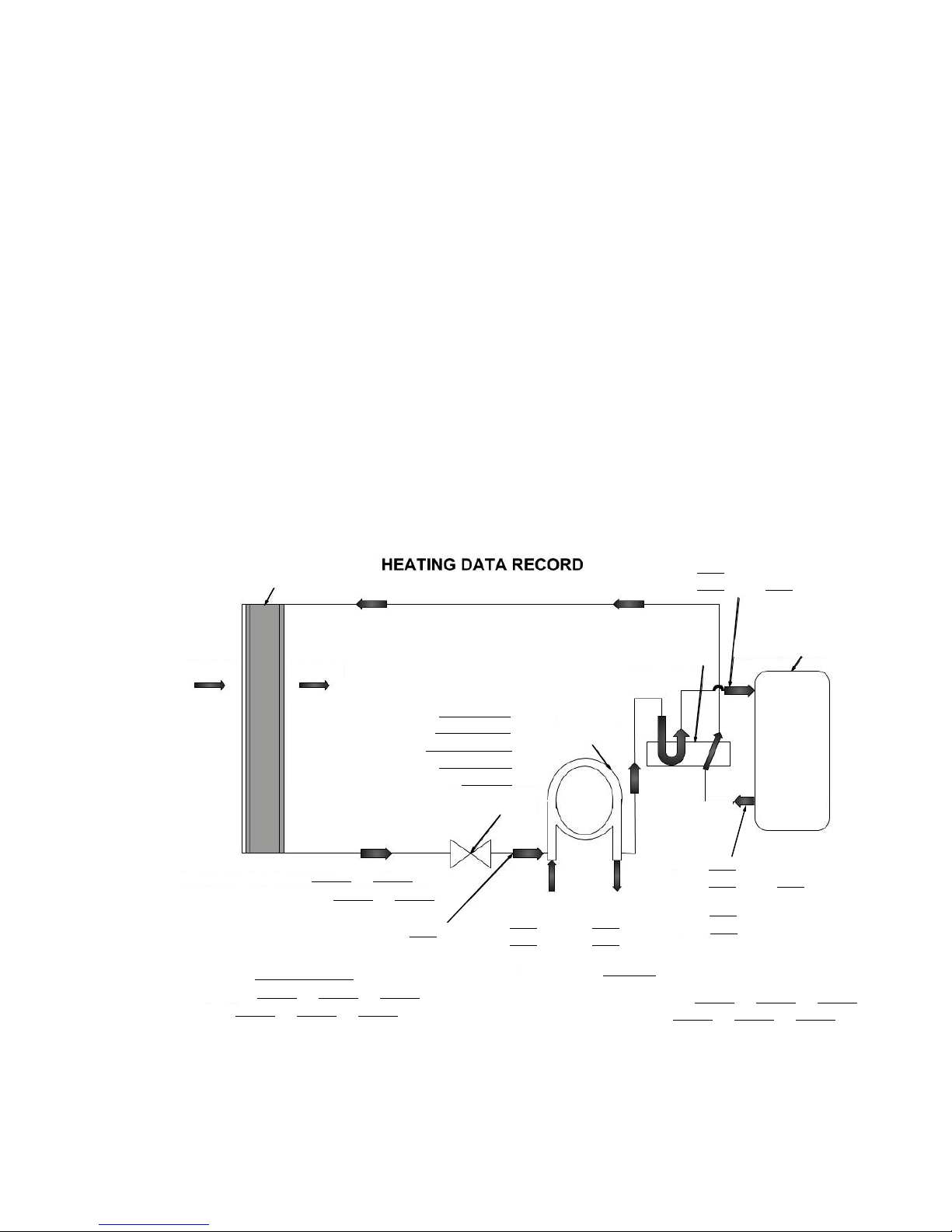
FORM 145.18-IOM1
_
_
_
Please attach a sketch of the duct(s) run with this form when
VERTICAL STACKED WATER SOURCE HEAT PUMP
HEATING AND COOLING DATA RECORD SHEET
INDOOR PACKAGED EQUIPMENT
Form 145.18-CL2
ISSUE DATE: 8/30/2018
APPENDIX
HEATING AND COOLING DATA RECORD SHEET
JOB NAME: _____________________________________
JOB ADDRESS: _________________________________
______________________________________________
INSTALLER: ____________________________________
SPECIAL QUOTES/OPTIONS (YES/NO): _____________
CABINET MODEL #: _____________________________
CHASSIS MODEL #: _____________________________
OPERATING MODE (HEATING/COOLING): ___________
DUCTED/FREE DISCHARGE: ______________________
LENGTH, WIDTH, HEIGHT OF DUCT(S): _____________
SUPPLY DUCT EXTERNAL STATIC PRESSURE (iwg):
______________________________________________
______________________________________________
UNIT INFORMATION
JOB #: _________________________________________
DATE: _________________________________________
INSTALLER'S ADDRESS: _________________________
_______________________________________________
SERVICE TECHNICIAN: __________________________
CABINET SERIAL #: _____________________________
CHASSIS SERIAL #: _____________________________
LOCATION / ROOM # OF HEAT PUMP: ______________
FLASH CODES OR FAULTS FROM CONTROL BOARD:
_______________________________________________
DOES UNIT HAVE AN INTERNAL PUMP: (YES/NO): ____
SUPPLY AIRFLOW MEASUREMENT (CFM): _________
returned to the Applied Ducted Systems PTS team.
Air Coil
Airflow Airflow
Coil Inlet (Dry Bulb)
Coil Outlet (Dry Bulb)
Coil Inlet (Wet Bulb)
Coil Outlet (Wet Bulb)
Air Relative Humidity (%)
Reversing Valve
°F
°F
°F
Coaxial
Coil
°F
°F
Expansion Valve
L3
L2
L2
L3
°F
Liquid Line
Water In
°F
psi
Water Flow:
Water Out
°F
psi
GPM
Compressor Amp Draw: L1
Compressor Voltage: L1
*May only need L1 and L2 lines
Internal Pump Voltage: L1
Internal Pump Amp Draw: L1
*If installed
Fan Motor Speed:
Fan Amp Draw: L1
Fan Voltage: L1
L2
L2
*May only need L1 and L2 lines
°F
psi = SAT °F
Compressor
Suction
Discharge
°F
psi = SAT °F
Superheat
Sub-cooling
L2
L2
L3
L3
49
Page 50
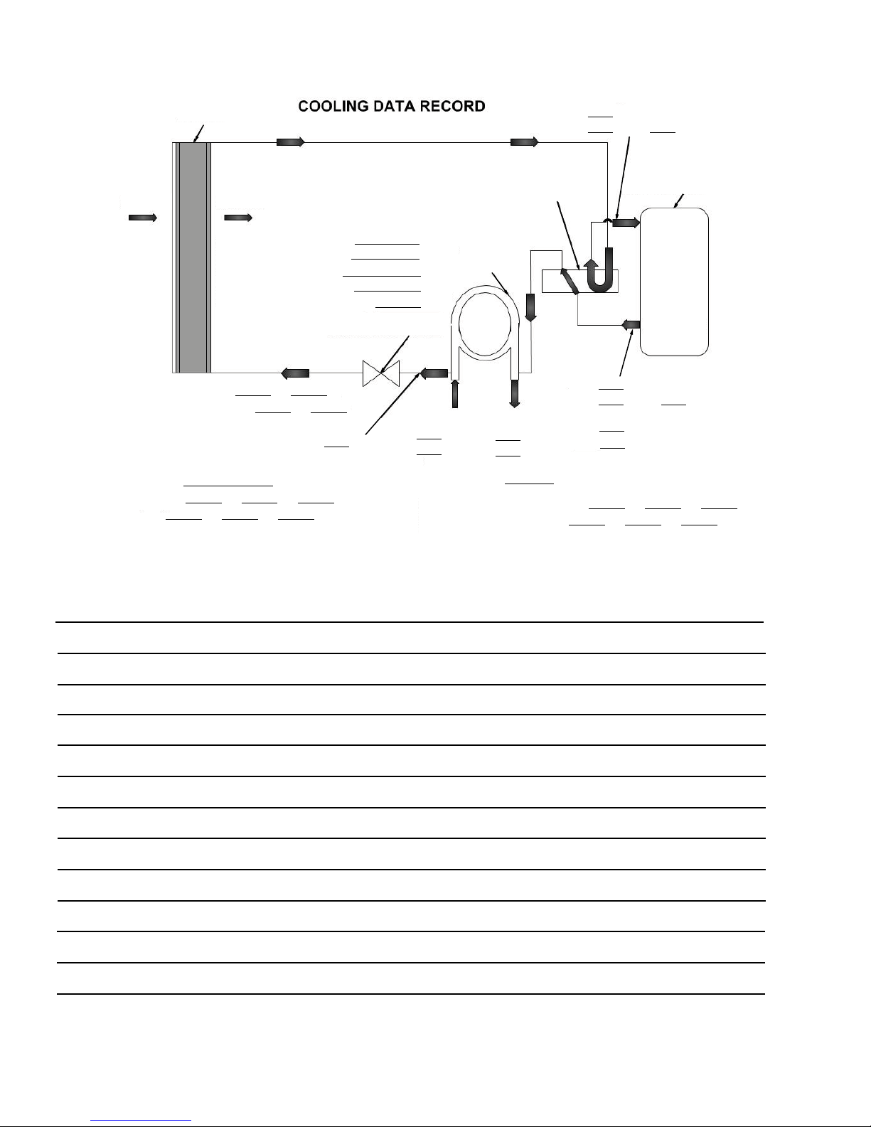
APPENDIX
NOTES
Air Coil
Airflow Airflow
Coil Inlet (Dry Bulb)
Coil Outlet (Dry Bulb)
Coil Inlet (Wet Bulb)
Coil Outlet (Wet Bulb)
Air Relative Humidity (%)
°F
°F
°F
°F
°F
Expansion Valve
Coaxial
Coil
Reversing Valve
Internal Pump Voltage: L1
L2
Internal Pump Amp Draw: L1
L2
*If installed
Fan Amp Draw: L1
L2
*May only need L1 and L2 lines
L3
Fan Voltage: L1
L2
L3
Fan Motor Speed:
°F
Liquid Line
°F
Water In
psi
°F
Water Out
psi
Water Flow:
GPM
Compressor Amp Draw: L1
L2
*May only need L1 and L2 lines
L3
Compressor Voltage: L1
L2
L3
°F
psi = SAT °F
Superheat
Sub-cooling
Suction
Discharge
Compressor
°F
psi = SAT °F
FORM 145.18-IOM1
ISSUE DATE: 8/30/2018
50
Page 51

FORM 145.18-IOM1
ISSUE DATE: 8/30/2018
R-410A QUICK REFERENCE GUIDE
See Section 1 - Installation for specific installation requirements.
• R-410A refrigerant operates at 50–70% higher
pressures than R-22 refrigerant. Ensure that servicing equipment and replacement components
are designed to operate with R-410A refrigerant.
• R-410A refrigerant cylinders are rose colored.
• Recovery cylinder service pressure rating must be
400 psig (DOT 4BA400 or DOT BW400).
• Recovery equipment must be rated for R-410A
refrigerant.
• Do not use R-410A service equipment on R-22
systems. All hoses, gauges, recovery cylinders,
charging cylinders, and recovery equipment must
be dedicated for use on R-410A systems only.
• Manifold sets must be at least 700 psig high side
and 180 psig low side with a 550 psig retard.
• All hoses must have a service pressure rating of
800 psig.
• Leak detectors, must be designed to detect HFC
refrigerants.
• Systems must be charged with refrigerant. Use a
commercial type metering device in the manifold
hose.
• R-410A refrigerant can only be used with polyester (POE) type oils.
• POE type oils rapidly absorb moisture from the
atmosphere.
• Vacuum pumps cannot remove moisture from
POE type oils.
• Do not use liquid line driers with a working pressure rating less than 600 psig.
• Do not install suction line driers in the liquid line.
• A liquid line drier is required on every unit.
• Do not use an R-22 TXV. If a TXV is necessary, it
must be an R-410A TXV.
• Never open the system to atmosphere when under
vacuum.
• If the system must be opened for service, evacuate
the system, then break the vacuum with dry nitro-
gen and replace the lter driers.
51
Page 52

100 JCI Way, York, Pennsylvania USA 17406-8469 800-861-1001 Subject to change without notice. Printed in USA
Copyright © by Johnson Controls 2018 www.johnsoncontrols.com ALL RIGHTS RESERVED
Form 145.18-IOM1 (818)
Issue Date: August 30, 2018
Supersedes: 145.18-IOM1 (115)
 Loading...