

Page 1
VRF Smart Gateway Installation Instructions
SI-VRFCBN02-0Sx
Part No. 24-10143-1183, Rev. B
Refer to the QuickLIT website for the most up-to-date version of this document.
Update Software
Important: A software update may be available for your
device. Visit VRFPro.com or contact your
nearest Johnson Controls representative
for the latest version. Refer to the VRF
Smart Gateway User's Guide
(LIT-12012385) for instructions on applying
updates.
Applications
The Johnson Controls® VRF Smart Gateway enables
the integration of the Hitachi VRF system with a building
automation system (BAS), such as the Metasys® system.
The VRF Smart Gateway performs this function by
communicating between the native H-Link
communications network of the Hitachi VRF system and
the open building standard BACnet®/IP network. The
VRF Smart Gateway intelligently provides the VRF device
and point data over the BACnet/IP network in a way that
the BAS can easily discover. The VRF Smart Gateway
therefore requires little or no post-integration configuration
within the BAS. The VRF Smart Gateway includes a
simple web server that provides a wireless mobile user
interface for configuring communication parameters and
performing VRF system discovery and device naming.
The wireless connection on the VRF Smart Gateway
allows users of a supported mobile device to be up to 30
m (100 ft, line of sight) away. Power must be supplied
using the provided external power supply.
North American Emissions Compliance
United States
This equipment has been tested and found to comply
with the limits for a Class A digital device pursuant to
Part 15 of the FCC Rules. These limits are designed to
provide reasonable protection against harmful
interference when this equipment is operated in a
commercial environment. This equipment generates,
uses, and can radiate radio frequency energy and, if not
installed and used in accordance with the instruction
manual, may cause harmful interference to radio
communications. Operation of this equipment in a
residential area may cause harmful interference, in which
case the users will be required to correct the interference
at their own expense.
RF Transmitters: Compliance Statement (Part 15.19)
This device complies with Part 15 of the FCC Rules.
Operation is subject to the following two conditions:
1. This device may not cause harmful interference, and
2. This device must accept any interference received,
including interference that may cause undesired
operation.
Warning (Part 15.21)
Changes or modifications not expressly approved by the
party responsible for compliance could void the user’s
authority to operate the equipment.
(barcode for factory use only)
Software Release 1.0
Issued April 2017
RF Exposure (OET Bulletin 65)
To comply with FCC RF exposure requirements for
mobile transmitting devices, this transmitter should only
be used or installed at locations where there is at least
20 cm separation distance between the antenna and all
persons.
1VRF Smart Gateway Installation Instructions
Page 2
Canada
Industry Canada Statement
The term IC before the certification/registration number
only signifies that the Industry Canada technical
specifications were met.
Le terme « IC » précédant le numéro
d'accréditation/inscription signifie simplement que le
produit est conforme aux spécifications techniques
d'Industry Canada.
Installation
Parts Included
• VRF Smart Gateway
• Installation Instructions
•
VRF Smart Gateway Quick Start Guide (Part No.
24-10737-156)
Note: A power adapter is available to order separately.
Contact the nearest Johnson Controls
representative to order.
Special Tools Needed
The unit supports both DIN rail and surface mounting
options. If the unit is permanently mounted to a vertical
surface without a DIN rail, you need screws to mount the
unit. The specific screw types depend upon the surface
to which the unit is mounted. The screw holes on the VRF
Smart Gateway can accommodate M3.5 and #6 screws.
To configure the VRF Smart Gateway using the gateway's
Wi-Fi access point, you need a mobile device (tablet or
smartphone) or computer (laptop or desktop) that
supports Wi-Fi.
Location Considerations
Observe the following guidelines when mounting a VRF
Smart Gateway:
• Mount the VRF Smart Gateway in areas free of
corrosive vapors and observe the environmental
limitations listed in the Technical Specifications
section of this document.
• Objects (including ductwork, cabinets, doors, and
glass) can impede the wireless signal. Minimize the
number of objects between the connected computer
or mobile device and the VRF Smart Gateway. Use
line of sight, if possible.
• Metal objects (such as cabinet doors, enclosures, and
pipes) and concrete objects (such as pillars, walls,
and ceilings) may limit Wi-Fi service. To
accommodate potential structural obstacles on site,
the VRF Smart Gateway can be mounted flush
against the wall or perpendicular to it.
• The VRF Smart Gateway is not rated for outdoor
mounting.
Mounting Locations
The VRF Smart Gateway can be attached to a 1-1/8 in.
(35 mm) DIN rail or a flat, vertical surface. Mounting the
unit on a ceiling or in a way that positions the front of the
unit facing down is not recommended.
Although the unit has two mounting clips, only the bottom
clip snaps inward. The top clip is permanently locked in
the outward position, and it can be used as an additional
hole for screwing the unit into place. If not utilized for DIN
rail or surface mounting, the top and bottom clips may
be removed from the unit.
DIN Rail Mounting
To mount the unit on a DIN rail:
Mounting
We recommend mounting the unit either vertically (upright
and flush) or horizontally (sideways and flush). This
flexibility allows the unit to be mounted in a way that
minimizes spacial constraints and maximizes placement
options for optimal wireless signal strength.
The unit should be mounted in such a way that labels
can be read if they are visible. (For example, do not mount
the unit upside down, which puts the labels upside down.)
1. Securely mount a 3 in. (7.5 cm) or longer section of
1-1/8 in. (35 mm) DIN rail in the required space.
2. On the unit, pull the bottom mounting clip outward to
the extended position.
2VRF Smart Gateway Installation Instructions
Page 3

Figure 1: Positioning the Unit on a DIN Rail
Figure 2: Sample Permanent Mounting, Back-side
Screws
3. Hang the unit on the DIN rail by the hooks at the top
of the DIN rail channel (on the back of the bracket),
and position the unit snugly against the DIN rail.
4. Push the bottom-mounting clip inward to secure the
unit on the DIN rail.
Wall Mounting
The unit may be mounted using the holes in the DIN rail
clips. This orientation helps accommodate on-site
constraints. Screw hole locations are illustrated in Figure
3.
The screw types needed to mount the unit depend upon
the surface to which the unit is mounted. The screw holes
on the VRF Smart Gateway can accommodate M3.5 and
#6 screws.
For information on location considerations for maximizing
signal strength, see the Mounting section.
To mount the unit on a flat surface (such as a wall):
1. Pull the bottom mounting clip outward to the extended
position.
2. Mark mounting hole locations on the wall using the
dimensions shown in the following figure; or hold the
bracket against the wall and mark the hole locations
through the mounting clips.
Note: The position of the location holes depends on
whether the bracket is mounted horizontally
or vertically.
3VRF Smart Gateway Installation Instructions
Page 4
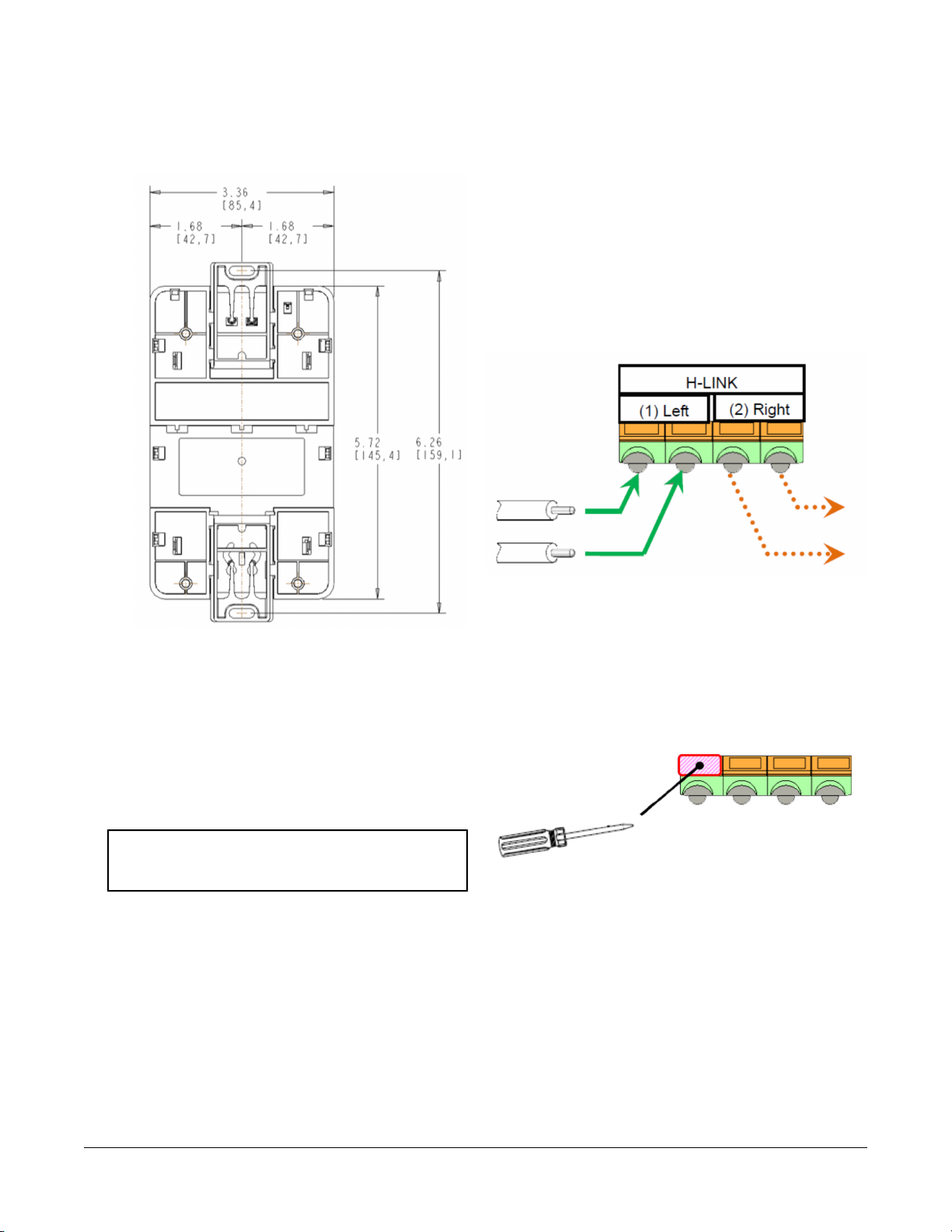
Figure 3: Mounting Holes, Flat Mounting, DIN
Rail Screws, in. (mm)
Wiring the H-Link Network
To wire the H-Link Network of the VRF Smart Gateway:
• Connect the two H-Link cable wires to the left
terminals indicated in the following figure.
• If the VRF Smart Gateway is connected at an
intermediate position of the H-Link network as
opposed to the end of the network segment, use the
right terminals shown in the following figure to
continue the H-Link network.
Figure 4: H-Link Cable Insert Position
Note: The screw holes on the VRF Smart Gateway
can accommodate M3.5 and #6 screws.
3. Drill holes in the wall based on the locations marked
in the preceding step, and insert wall anchors for each
hole (if necessary).
4. Hold the unit in place, insert the screws through the
mounting clips and into the screw holes, and then
carefully tighten all screws.
Important: Do not overtighten the mounting screws.
Overtightening the screws may damage
the mounting clips or bracket.
Wiring
Wiring Consideration and Guidelines
Observe the following guidelines when wiring the VRF
Smart Gateway:
• Do not allow the VRF Smart Gateway to hang from
a cable connection.
• Provide some slack in the cable between the VRF
Smart Gateway and the controller or other device to
which you are connecting.
To insert or remove the H-Link cable wires:
• Push the orange tabs using a small, flat screwdriver
or similar tool as indicated in the following figure.
• Then, insert or remove the wire and release the tab.
Figure 5: Inserting or Removing the H-Link Cable
Wires
Ethernet Port
The Ethernet port on the VRF Smart Gateway is an 8-pin
RJ-45 jack. The maximum allowable cable length is 328
ft (100 m). The Ethernet port on the VRF Smart Gateway
connects to the BAS by using an Ethernet switch or
similar networking equipment.
4VRF Smart Gateway Installation Instructions
Page 5
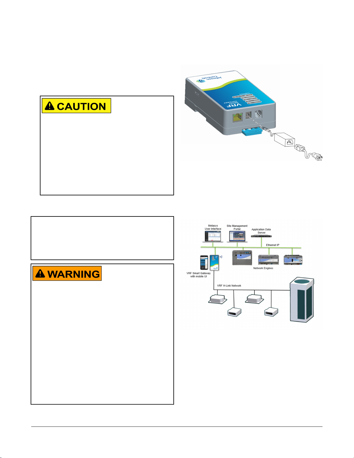
External Power Supply Connections
To connect the VRF Smart Gateway using the supplied
external power source:
1. Connect the 15 VDC output connector of the power
supply to the power supply port of the VRF Smart
Gateway.
Risk of Property Damage. Do not apply power to
the system before checking all wiring connections.
Short-circuited or improperly connected wires may
result in permanent damage to the equipment.
MISE EN GARDE:
Risque de dégâts matériels. Ne pas mettre le
système sous tension avant d'avoir vérifié tous les
raccords de câblage. Des fils formant un court-circuit
ou connectés de façon incorrecte risquent
d'endommager irrémédiablement l'équipement.
2. Connect the power supply to the supplied power cord.
3. Plug the power cord into a 100 to 240 VAC outlet.
Important: Power should only be applied and removed
by connecting and disconnecting the power
cord from the 100 to 240 VAC outlet.
Applying or removing power by connecting
or disconnecting the 15 VDC connector can
damage the unit.
Figure 6: VRF Smart Gateway with Sample External
Power Supply
Operation
The easiest way to initially configure the VRF Smart
Gateway is by connecting to the gateway's Wi-Fi network.
Figure 7: Connecting VRF Equipment to the Metasys
System
Risk of Electric Shock. Disconnect or isolate all power
supplies before making electrical connections. More than
one disconnection or isolation may be required to
completely de-energize equipment. Contact with
components carrying hazardous voltage can cause
electric shock and may result in severe personal injury
or death.
AVERTISSEMENT:
Risque de décharge électrique. Débrancher ou isoler
toute alimentation avant de réaliser un branchement
électrique. Plusieurs isolations et débranchements sont
peut-être nécessaires pour -couper entièrement
l'alimentation de l'équipement. Tout contact avec des
composants conducteurs de tensions dangereuses
risque d'entraîner une décharge électrique et de
provoquer des blessures graves, voire mortelles.
Connecting to the VRF Smart Gateway Wi-Fi Network
1. In the Wi-Fi settings of your device or laptop, connect
to the VRF Smart Gateway Wi-Fi network using your
default credentials. These credentials are included
on a label in the VRF Smart Gateway Quick Start
Guide (Part No. 24-10737-156) that came with your
device.
2. Direct your browser to www.myvrfsg.com to open
the VRF Smart Gateway browser interface.
5VRF Smart Gateway Installation Instructions
Page 6

Note: VRF Smart Gateway ships with a private
myvrfsg.com SSL certificate installed to ensure
secure communication with the VRF Smart
Gateway. However, this certificate does not
indicate that it is trusted in a browser. If you
wish to install your own certificate, refer to
Adding a Private Key and Certificate to VRF
Smart Gateway in the VRF Smart Gateway
Network and IT Guidance Technical Bulletin
(LIT-12012341).
3. Read and accept the VRF Smart Gateway license
agreement.
4. The first time you log in to the VRF Smart Gateway,
the Change Password and Passphrase web page
appears. You must change the Admin password and
Wi-Fi passphrase.
Important: After you change the Wi-Fi passphrase
or SSID, the web server restarts and
you must rejoin the VRF Smart Gateway
Wi-Fi network using the new
passphrase. On some mobile devices,
you must select and forget the original
VRF Smart Gateway Wi-Fi network
before rejoining the network with the
new passphrase.
Change the default password in the New Admin
Password field. Confirm the change by entering the
new password in the Verify New Admin Password
field.
Change the Wi-Fi Passphrase in the New Wi-Fi
Passphrase field and click Save.
Once you have established Wi-Fi connection to the VRF
Smart Gateway, you can begin to configure the gateway
settings in the Settings menu as explained in the Users
Guide. When the gateway is physically connected to the
H-Link network, the VRF Smart Gateway automatically
starts to discover the VRF system and devices. View the
Device List from the VRF Smart Gateway UI to see the
discovered VRF devices.
Reset Button Operation and Descriptions
If you lose your password or if you want to restore the
unit to factory defaults, the VRF Smart Gateway offers
two reset functions: a Network Reset function that resets
Wi-Fi and Ethernet settings, and a Reset to Factory
Defaults function that resets all unit settings (including
user-configured VRF equipment names and descriptions).
Reset to Factory Defaults also resets your SSL certificate
to the Johnson Controls self-signed certificate that is in
the device when it comes from the factory.
For information on resetting the unit, see Table 1.
Important: To use a unit that is reset to factory defaults,
you must have the default login information
supplied in the Quick Start Guide that
shipped with the unit. The Reset to Factory
Defaults function does not change the
version of the application. If you did a
software upgrade, the VRF Smart Gateway
remains at the upgraded version rather than
resetting to the version that it was running
when it left the factory.
The reset button is on the side of the device, and it is
embedded into the VRF Smart Gateway housing so that
it cannot be activated by accident. To reach the reset
button, use a paper clip, pin, or similar tool.
Notes:
• If you are connected to the network, using the reset
button disconnects you.
• If you press the reset button for more than 9 seconds,
the reset operation is cancelled.
• If a fault condition already exists, the reset button is
disabled.
A software update may be available for your device. Visit
VRFPro.com or contact your nearest Johnson Controls
representative for the latest version. Refer to the VRF
Smart Gateway User's Guide (LIT-12012385) for
instructions on applying updates.
6VRF Smart Gateway Installation Instructions
Page 7

Figure 8: Using the Reset Button Table 1: Reset Button Operation and Descriptions
Reset
Reset Operation
2
Function
Reset Wi-Fi
and Ethernet
Settings
Reset to
Factory
Defaults
1. Press and hold the reset button for 2
seconds. The Fault LED displays Slow
Flicker behavior.
2. Release the reset button within 3
seconds. The Fault LED continues Slow
Flicker behavior.
3. Within 5 seconds, press the reset button
again, and then immediately release it to
confirm that you wish to reset Wi-Fi and
Ethernet settings. (If you do not press the
reset button to confirm within 5 seconds,
the reset operation is cancelled.)
The Wi-Fi (SSID and passphrase) and
Ethernet settings are reset to factory
defaults. The LEDs stop flickering for 2
seconds, and then the LEDs return to
normal operation, based on the current
state of the device.
1. Press and hold the reset button for 6
seconds. After 2 seconds, the Fault LED
1
displays Slow Flicker behavior. This
changes to Fast Flicker behavior after an
additional 4 seconds of holding the reset
button.
2. Release the reset button within 3 seconds
of seeing Fast Flicker behavior. The Fault
LED continues Fast Flicker behavior.
3. Within 5 seconds, press the reset button
again, and then immediately release it to
confirm that you wish to reset to factory
defaults. (If you do not press the reset
button to confirm within 5 seconds, the
reset operation is cancelled.)
4. All unit settings are reset to factory
defaults. The LEDs stop flashing for 2
seconds, and then the LEDs return to
normal operation, based on the current
state of the device.
1 Resets all unit settings, including user profiles.
2 For information on LED designations and flicker behavior,
see Table 2.
7VRF Smart Gateway Installation Instructions
Page 8

Status Indication LEDs
The VRF Smart Gateway communicates status using
LEDs to indicate the following functional states:
• power
• fault
• H-Link bus communication
• Ethernet communication
• Wi-Fi strength
See the following table for a comprehensive list of VRF
Smart Gateway LED functional information.
VRF Smart Gateway LED Designations and Descriptions
Table 2: LED Designations and Descriptions
Descriptions/Other
Conditions
Off = No power
On Steady = Power
supplied by primary
voltage
Off = No faults/normal
operation
On Steady = Missing
hardware, missing
software, operating
system has not yet
initialized, or reset is
in progress.
Slow Flicker (1 blink in
a second) = Software
upgrade in progress
Medium Flicker (2
blinks in a second) =
Startup sequence
Fast Flicker (5 blinks
in a second) = Fault
Off = No data
transmitting
Flicker = Discovering
VRF devices
On Steady =
Discovery complete
Name
NormalColorLED
GreenPower
On Steady
(no flashing)
OffRedFault
FlickerGreenH-Link Bus
Table 2: LED Designations and Descriptions
NormalColorLED
Name
On SteadyGreenEthernet
On SteadyYellowWi-Fi
Descriptions/Other
Conditions
Off = Communication
not established
On Steady =
Communication
established
Flicker = Data
transmission
Off = No Wi-Fi signal
or no devices currently
connected over Wi-Fi
Wi-Fi strength is
indicated by the
number of LEDs that
are lit, with one lit LED
indicating weak
wireless signal
strength (between 1%
and 49%) and three lit
LEDs indicating
excellent wireless
signal strength (at
least 75%).
LED Test Sequence at Startup
During startup, the VRF Smart Gateway automatically
initiates a self-test to verify proper operation of the unit.
Immediately after connecting supply power, the following
LED lighting sequence occurs:
1. The Power LED turns on, and stays lit.
2. The Fault LED indicator flashes for approximately 40
seconds, then turns off when the VRF Smart Gateway
is fully functional.
3. The Wi-Fi LEDs light up in succession (scanning),
indicating that the VRF Smart Gateway is waiting for
a device to join its Wi-Fi network.
Repair Information
If the VRF Smart Gateway fails to operate within its
specifications, replace it. The VRF Smart Gateway is not
a serviceable product; however, it does support software
updates to enable feature enhancements. For a
replacement unit, software updates, or accessories,
contact the nearest Johnson Controls representative.
Do not open the VRF Smart Gateway housing. The VRF
Smart Gateway has no user-serviceable parts inside.
8VRF Smart Gateway Installation Instructions
Page 9

The VRF Smart Gateway does not require periodic field
maintenance.
Troubleshooting
Table 3: Launch Issues Troubleshooting Information
ResolutionProblem
You are not directed to the VRF
Smart Gateway login page when
you launch a web browser.
Every time I install the SSL
certificate on my device, it asks me
to re-install it. What should I do?
When I install the SSL key or
certificate, I receive the message
Error Saving SSL Settings.
Reason
Device behavior can vary based on the device and Internet browser in use. For instance,
some devices cache browser information and do not automatically redirect users to the
VRF Smart Gateway login page when the browser is launched.
Resolution
Make sure that your device is connected to the VRF Smart Gateway's Wi-Fi network.
Direct your browser to www.myvrfsg.com.
If the login page is taking too long to load, try using the Ethernet connection instead.
Resolution
Check your web browser settings and verify that cookies are enabled.
When an SSL key or certificate is corrupted, the SSL page detects it and alerts you to the
corrupted key or certificate.
However, if the corruption is minor, for example, an extra space was copied while installing
the certificate or a character was missed, the UI does not detect the problem and allows
the corrupted key or certificate to be saved. The server detects the error and returns the
Error Saving SSL Settings message. While this correctly prevents the bad key or
certificate from being used, it does not inform you as to the source of the problem.
In this case, reinstall the SSL key or certificate as described in the VRF Smart Gateway
Network and IT Guidance Technical Bulletin (LIT-12012341).
Refer to the VRF Smart Gateway User's Guide (LIT-12012385) for information on Ethernet settings and SSL settings.
Technical Specifications
Table 4: VRF Smart Gateway
Product Code
Ambient Temperature
Conditions
Ambient Humidity
Conditions
Transmission Power
(Typical)
WLAN Receiver
Sensitivity (Typical)
1
SI-VRFCBN02-0Sx: VRF Smart Gateway (Includes VRF Smart Gateway and 100 to 240 VAC power
supply.)
12 to 15 VDC at 5.2 W maximumPower Consumption
Operating: 0 to 50°C (32 to 122°F)
Operating Survival: -30 to 60°C (-22 to 140°F)
Non-Operating: -40 to 70°C (-40 to 158°F)
Storage: 5 to 95% RH 30°C (86°F) maximum dew point conditions
Operating: 5 to 95% RH, 30°C (86°F) maximum dew point conditions
Wireless Local Area Network (WLAN) Transmission Power:
CE Compliant levels
+14.5 dBm, 54 Mbps
+12.5 dBm, 65 Mbps
-76 dBm, 10% packet error rate (PER ), 54 Mbps
-73 dBm, 10% PER, 65 Mbps
9VRF Smart Gateway Installation Instructions
Page 10

Table 4: VRF Smart Gateway
Transmission Speeds
Transmission Range
(Typical)
Wireless Security
Interfaces
(H x W x D)
Weight
Web Browser
Requirements for
Computers and
Handheld Devices
Control
Wireless Communication:
2.4 GHz ISM bands, 802.11 b/g/n, 11/22/54 Mbps
Channel 6 preconfigured, supported CH 1 to 11 for United States and Canada, and CH 1 to 12 for all
other countries
Serial Communication (H-Link Bus):
9600 bps
Ethernet Communication:
10, 100 Mbps
Ethernet Communication:
100 m (328 ft) cable length
H-Link Bus Communication:
1,000 m (3,280 ft) cable length
Wireless Communication:
30 m (98 ft) line-of-sight indoors
91 m (299 ft) line-of-sight outdoors
Channel 6 preconfigured, supported CH 1 to 11 for United States and Canada, and CH 1 to 12 for all
other countries
WLAN Range Performance:
0 to 50 ft = Excellent
50 to 100 ft = Good
100 to 300 ft = Weakest, approaching out of range
WPA2-PSK TKIP (Wi-Fi Protected Access Pre-Shared Key mode Temporal Key Integrity Protocol)
WPA2-EAP-PEAP
WPA2-EAP-TLS
One H-Link port (4-pin port)Network and Serial
145.4 x 85.4 x 40.1 mm (5.72 x 3.36 x 1.58 in. when used vertically)Dimensions
0.21 kg (0.46 lb)
Note: Weights do not include an external power supply.
Computer:
Windows® Internet Explorer® 10 and Windows Internet Explorer 11, Apple® Safari® 6.1 and later,
and Google® Chrome™
Handheld Device:
The handheld device must be running either Internet Explorer Mobile for Windows Mobile version 5
or version 6 operating system (OS); Apple® iPhone® and iPod touch® iOS version 7.0 or greater;
Android™ 4.0.3, 4.0.4, and 4.1+, or Google Chrome. Other web browsers may display the UI, but the
functionality is not guaranteed.
Operating controlPurpose of Control
Electronic Independently Mounted ControlConstruction of
10VRF Smart Gateway Installation Instructions
Page 11

Table 4: VRF Smart Gateway
TYPE 1TYPE 1 or TYPE 2
Action
Pollution Degree 2External Pollution
Situation
330 VRated Impulse Voltage
100º C (212º F)Ball Pressure
Temperature
Compliance
United States UL Listed File E107041, ANSI/UL 60730-1, UL Standard for Automatic Electrical Controls
for Household and Similar Use.
Transmission Complies with FCC Part 15.247 Regulations for Low Power Unlicensed Transmitters
Transmitter FCC Identification: OEJ-MAPWIFI
FCC Compliant to CFR 47, Part 15, Subpart B, Class A
Canada: cUL Listed File E107041, CAN/CSA-E60730-1, Canadian Standard for Automatic Electrical
Controls for Household and Similar Use
Industry Canada IC: 279A-MAPWIFI
IC: RSS-210, ICES-003
Europe: CE Mark – Johnson Controls declares that this product is in compliance with the essential
requirements and other relevant provisions of the RED Directive, the EMC Directive, and the Low
Voltage Directive (LVD).
CE Emission: EN61000-6-3; Generic standards for residential, commercial, and light-industrial
environments. ETSI EN 301 489-1, ETSI EN301 489-3 (Class 2), IEC 60730-1/ EN 60730-1
1 Last digit (x) represents non-US country requirements.
The performance specifications are nominal and conform to acceptable industry standard. For application at conditions
beyond these specifications, consult the local Johnson Controls office. Johnson Controls shall not be liable for
damages resulting from misapplication or misuse of its products.
BACnet Points
The following table lists the indoor units (IDUs) as exposed by the VRF Smart Gateway.
Table 5: VRF BACnet Points for Indoor Units
Contents of InformationObject TypeObject DescriptionObject NameBACnet
Instance
Number
0~255ValueAIIndoor Unit Capacity CodeUNIT-CAP4
–––EnableShutdownSettingBOUnit Enable ModeUNITEN-MODE5
AutoHeatFanDryCoolSettingMOCommand System ModeSYSTEM-MODE6
–––TrueFalseStatusBIHeat/Cool RequiredHtClg-REQ7
SF-SPEED-C8
Speed
0.0~100.0%ValueAIExpansion Valve PositionEXPV-%9
-50~99°C / -58~210°FValueAILiquid Pipe TemperatureLIQ-PIPE-T10
-50~99°C / -58~210°FValueAIGas Pipe TemperatureGAS-PIPE-T11
-50~99°C / -58~210°FValueAIReturn Air TemperatureRA-T12
–AutoHighMediumLowSettingMOCommanded Supply Fan
11VRF Smart Gateway Installation Instructions
Page 12

Table 5: VRF BACnet Points for Indoor Units
Instance
Number
ZNSP-LO33
Lockout
Contents of InformationObject TypeObject DescriptionObject NameBACnet
-50~99°C / -58~210°FValueAIDischarge Air TemperatureDA-T13
-127~127°C / -260~260°FValueAICoil Differential TemperatureDIFF-T14
17~30°C / 62~86°FSettingAOZone Temperature SetpointZN-SP15
-50~99°C / -58~210°FValueAIRemote Zone TemperatureRZN-T16
0~255 HzValueAIRequested Compressor SpeedCOMP~REQ17
0~255ValueAIUnit Stop CodeUNIT-STOP-CODE18
0~255ValueAIAlarm CodeALARM-CODE19
–––TrueFalseStatusBIOptional Room ThermostatRMT-OPT20
–––TrueFalseStatusBIDefrost StatusDEFROST-S21
–––TrueFalseStatusBIRemote Control ConnectedREM-CON22
–––OnOffStatusBISupply Fan StatusSF-S23
–––AlarmNormalStatusBIUnit Alarm StatusALARM-S24
–HeatFanDryCoolStatusMIActual System ModeSYSTEM-S25
––HighMediumLowStatusMIActual Supply Fan SpeedSF-SPD26
-50~99°C / -58~210°FValueAIZone TemperatureZN-T27
–––DirtyCleanStatusBIFilter StatusFILT-S28
–––DirtyCleanSettingBOFilter Status ResetFILT-S-RESET29
–––LockUnlockSettingBOUnit LockoutUNIT-LO30
–––LockUnlockSettingBOFan Command LockoutFANCMD-LO31
–––LockUnlockSettingBOSystem Mode LockoutSYSMODE-LO32
–––LockUnlockSettingBOZone Temperature Setpoint
–––LockUnlockSettingBOFan Speed LockoutFANSPD-LO34
–––LockUnlockSettingBOLouver Position LockoutLOUVER-LO35
The following table lists the IDU custom enum values for SYSTEM-MODE and SYSTEM-S.
Table 6: IDU System Mode
Metasys Enum StringMetasys Enum Value
Cool1
Dry2
Fan3
Heat4
Auto5
The following table lists the IDU custom enum values for SF-SPEED-C and SF-SPD.
Table 7: IDU Fan Speed
Metasys Enum StringMetasys Enum Value
Low1
Med2
12VRF Smart Gateway Installation Instructions
Page 13

Table 7: IDU Fan Speed
Metasys Enum StringMetasys Enum Value
High3
Auto4
The following table lists the outdoor units (ODUs) as exposed by the VRF Smart Gateway.
Table 8: VRF BACnet Points for Outdoor Units
Contents of InformationObject TypeObject DescriptionObject NameBACnet
Instance
Number
0~255ValueAIAlarm CodeALARM-CODE3
StatusMISystem StatusSYSTEM-S7
StatusMIHeat Exchanger StateHX-STATE8
StatusMIInverter StateINV-STATE9
StatusMIFan Controller StateFAN-STATE10
INV-HRS11
Runtime
INV-FREQ13
Frequency
BYPEXPV-%17
Position
INV2ND-A21
Secondary Current
INVPRI-A22
Primary Current
INVTOP-T24
Temperature
COMP2TOP-T25
Temperature
StatusMIProtection CodePROT-CODE26
Several Values (See the Following Tables
for Custom Enum Information)
Several Values (See the Following Tables
for Custom Enum Information)
Several Values (See the Following Tables
for Custom Enum Information)
Several Values (See the Following Tables
for Custom Enum Information)
0~655,350 HoursValueAIInverter Compressor 1
0~655,350 HoursValueAICompressor 2 RuntimeCOMP-HRS12
0~255 HzValueAIInverter Compressor
0~65,535 HzValueAITotal FrequencyTOTAL-FREQ14
0~100%ValueAIOutdoor Fan OutputFAN-%15
0~100%ValueAIExpansion Valve PositionEXPV-%16
0~100%ValueAIBypass Expansion Valve
0~3,698.5 psiValueAIDischarge PressureDISCH-P18
0~369.8 psiValueAISuction PressureSUCT-P19
-50~99°C / -58~210°FValueAIOutside Air TemperatureOA-T20
0~127.0 AValueAIInverter Compressor
0~127.0 AValueAIInverter Compressor
0~127.0 AValueAICompressor 2 CurrentCOMP2-A23
0~99°C / 32~210°FValueAIInverter Compressor Top
0~99°C / 32~210°FValueAICompressor 2 Top
Several Values (See the Following Tables
for Custom Enum Information)
AutoCoolHeatStatusMISystem ModeSYSTEM-MODE6
–OnOffStatusBIDefrost StatusDEFROST-S27
–OnOffStatusBIEmergency Run StatusEMERGRUN-S28
13VRF Smart Gateway Installation Instructions
Page 14

Table 8: VRF BACnet Points for Outdoor Units
Instance
Number
The following table lists the ODU custom enum values for SYSTEM-MODE.
Table 9: ODU System Mode
Metasys Enum StringMetasys Enum Value
Heat1
Cool2
Auto3
The following table lists the ODU custom enum values for SYSTEM-S.
Table 10: ODU System Status
Metasys Enum StringMetasys Enum Value
Thermo off1
Pump down2
SW on start3
Thermo on start4
After defrost5
Start control 16
Start control 27
Normal8
Oil return9
Defrost ready 110
Defrost ready 211
Differential pressure control12
Defrost13
Contents of InformationObject TypeObject DescriptionObject NameBACnet
–RunStopStatusBIInverter StatusINV-S29
–RunStopStatusBIFan StatusFAN-S30
The following table lists the ODU custom enum values for HX-STATE.
Table 11: ODU Heat Exchanger Status
Metasys Enum StringMetasys Enum Value
Evaporator Mode Low Pressure1
Condenser Mode High Pressure2
Evaporator Mode3
Condenser Mode4
The following table lists the ODU custom enum values for INV-STATE and FAN-STATE.
Table 12: ODU Inverter and Fan Status
Metasys Enum StringMetasys Enum Value
Normal stop1
Fault2
14VRF Smart Gateway Installation Instructions
Page 15

Table 12: ODU Inverter and Fan Status
Metasys Enum StringMetasys Enum Value
Over current3
Fin temp4
Electronic thermal5
Undervoltage6
Overvoltage7
Communication error8
Current sensor abnormality9
Instantaneous power failure10
Na011
MPU reset12
Earth fault voltage13
Phase loss14
Na115
Driving prohibited area16
Fan controller retry17
Control abnormality18
Na219
Na320
Loss of synchronism21
Na422
Na523
Normal acceleration24
Normal deceleration25
Constant speed26
Overload after the acceleration27
Overload after the deceleration28
Overload after constant speed29
Power supply unbalance30
Power supply phase loss31
Na632
The following table lists the ODU custom enum values for PROT-CODE.
Table 13: ODU Protection Code
Metasys Enum StringMetasys Enum Value
Pressure ratio1
Pd rise prevention2
Current protection3
INV module temp rise prevent4
Compressor top overheat prevent5
Ps drop or rise prevention6
15VRF Smart Gateway Installation Instructions
Page 16

Table 13: ODU Protection Code
JOHNSON CONTROLS
WESTENDHOF 3
45143 ESSEN
GERMANY
Metasys Enum StringMetasys Enum Value
Na17
Na28
Pd drop prevention9
Current demand10
Na311
Na412
Ps rise prevention13
JOHNSON CONTROLS
507 E MICHIGAN ST
MILWAUKEE WI 53202
USA
APAC Single Point of Contact:NA/SA Single Point of Contact:European Single Point of Contact:
JOHNSON CONTROLS
C/O CONTROLS PRODUCT
MANAGEMENT
NO. 22 BLOCK D NEW DISTRICT
WUXI JIANGSU PROVINCE 214142
CHINA
Building Technologies & Solutions
507 E. Michigan Street, Milwaukee, WI 53202
Metasys® and Johnson Controls® are registered trademarks of Johnson Controls.
All other marks herein are the marks of their respective owners.© 2017 Johnson Controls
www.johnsoncontrols.comPublished in U.S.A.
16VRF Smart Gateway Installation Instructions
 Loading...