

Johnson Controls VMA 1410, VMA 1400 Series, VMA 1430, VMA 1420 Overview And Engineering Manuallines
Page 1

Technical Bulletin
Issue Date February 28, 2006
Variable Air Volume Modular Assembly (VMA) 1400
Series Overview and Engineering Guidelines
VMA1400 Series Overview and Engineering Guidelines ...................2
Introduction......................................................................................................... 2
Key Concepts...................................................................................................... 3
VMA1400 Series Models...................................................................................................3
VAV System......................................................................................................................6
Definition of Terms............................................................................................................9
Room Sensor Placement ................................................................................................10
Pressure Independence..................................................................................................10
VMA Airflow Rate............................................................................................................10
Power Source..................................................................................................................11
N2 Bus Rules..................................................................................................................12
Inputs and Outputs..........................................................................................................13
Zone Bus.........................................................................................................................14
CablePRO.......................................................................................................................15
CVTPRO.........................................................................................................................15
Related Documentation...................................................................................................16
Application Examples......................................................................................................17
Reference Information.....................................................................................................26
Specifications..................................................................................................................27
Detailed Procedures.........................................................................................32
Determining VAV Box Requirements..............................................................................32
Establishing the Room Schedule....................................................................................32
Developing the Bill of Material and Placing Orders.........................................................33
Configuring the VMA.......................................................................................................35
© 2006 Johnson Controls, Inc. www.johnsoncontrols.com
Code No. LIT-6363120
Page 2

VMA1400 Series Overview and Engineering Guidelines Technical Bulletin 2
VMA1400 Series Overview and
Engineering Guidelines
Introduction
The Variable Air Volume Modular Assembly (VMA) 1400 Series is a
configurable, integrated module that includes a Variable Air Volume
(VAV) controller, differential pressure sensor, and, with the exception
of the VMA1430, an actuator.
Note: This document focuses on the VMA1410, 1420, and 1430
controllers. The VMA1400 Series also includes the VMA1440, which
is used exclusively as part of the Metasys® Zoning Package. See the
Metasys Zoning Package Product Bulletin (LIT-639050) and the
Metasys Zoning Package Overview Technical Bulletin (LIT-639100)
for information on this specialized product.
The VMA engineering procedures vary from location to location. The
information provided here is a general engineering guideline. Where
available, use the Advanced Installation Management (AIM) tools for
developing schedules and drawings.
This document provides a VMA1400 Series overview and describes
how to:
determine VAV box requirements
establish the room schedule
develop bills of material and place orders
configure the VMA
Page 3
VMA1400 Series Overview and Engineering Guidelines Technical Bulletin 3
Key Concepts
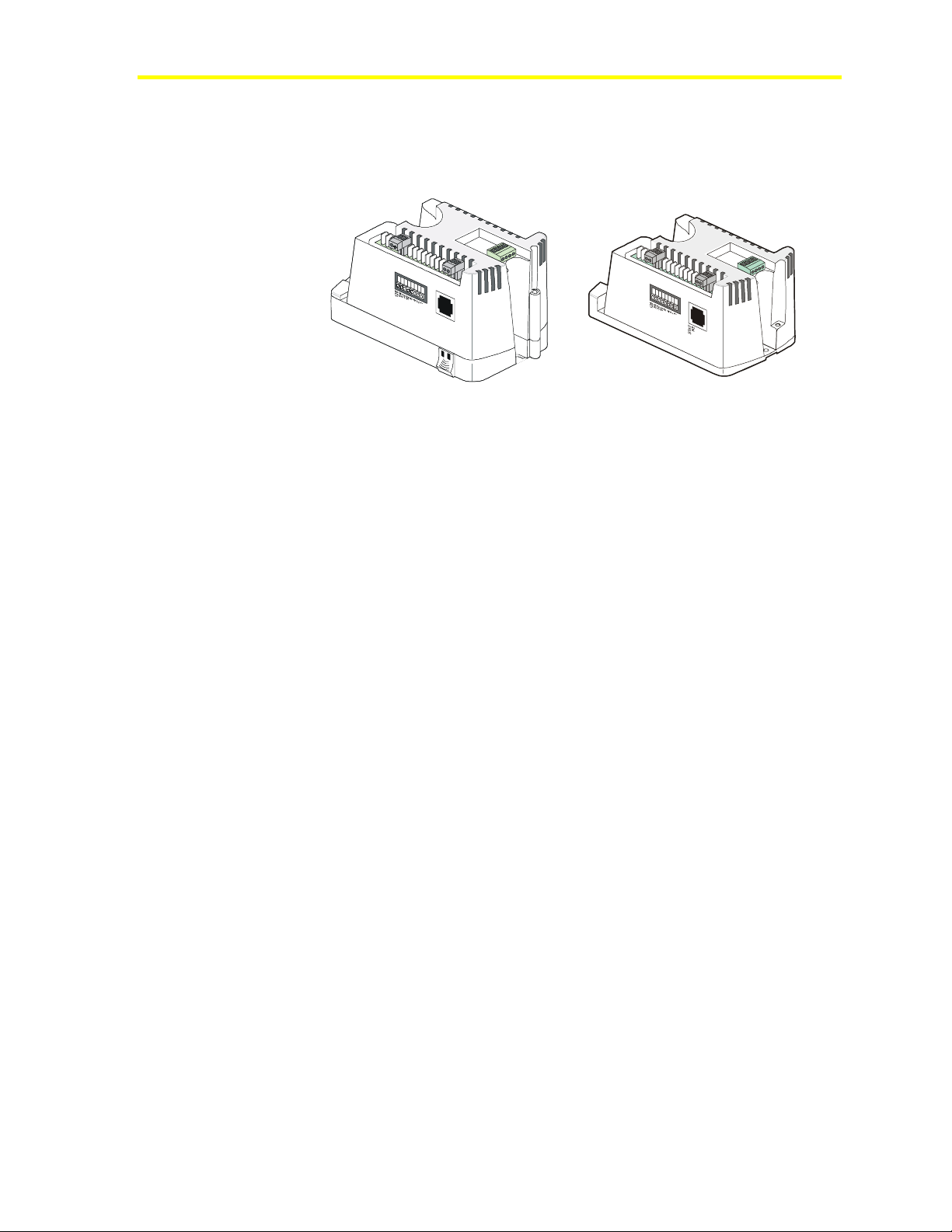
VMA1400 Series Models
VMA1410
VMA1420
Figure 1: VMA1400 Series Models
VMA1430
VMA14xx
The VMA is a configurable, integrated module that includes a VAV
controller and differential pressure sensor. The VMA1400 Series
includes three models:
VMA1410 (cooling only, includes actuator)
VMA1420 (cooling with reheat, includes actuator)
VMA1430 (controller and differential pressure sensor only for use
with an external incremental or proportional actuator)
Note: The VMA1400 Series also includes the VMA1440, which is
used exclusively as part of the Metasys Zoning Package. See the
Metasys Zoning Package Product Bulletin (LIT-639050) and the
Metasys Zoning Package Overview Technical Bulletin (LIT-639100)
for information on this specialized product.
The models are designed for pressure independent, single duct
(all VMA1400 Series models), and dual duct (VMA1420 and
1430 only) applications. The VMA1420 and 1430 models can be used
with parallel or series fan-powered boxes.
Note: The VMA1420 can be configured for the Metasys Zoning
Package application, but the internal pressure sensor can only be used
for monitoring purposes. Refer to the Metasys Zoning Package
Commissioning Technical Bulletin (LIT-639250).
Page 4

VMA1400 Series Overview and Engineering Guidelines Technical Bulletin 4
Table 1: VMA1400 Series Comparison Checklist
VMA Features 1410 1420 1430 Comments
Applications
Pattern Recognition Adaptive
Control (PRAC) on Zone Proportional
plus Integral plus Derivative (PID)
Temperature Loops
Adaptive Flow Control Loops
Single Duct, Pressure Independent
VAV
Side Loops without Interlocking
Single Duct Supply/Exhaust VAV
Fan Powered Boxes
Incremental, Proportional
Two Position, and Three Stages of
Box Heat
Incremental, Proportional
Two Position, or One Stage
Supplemental Heat
Dual Duct, Pressure Independent
VAV
Damper Actuator (Internal)
Accurate Positioning
Stall Detection
Automatic Damper End Stop
Detection at Power Up
Clockwise (CW)/
Counterclockwise (CCW)
Rotation Selection
EP8000 with Pneumatic Actuator
Software Tools
Ability To Download Code Firmware
Diagnostics
Moving Average Flow/Temperature
Diagnostic
Actuator Stall
Flow Test
Data Graphing
Starved Box Detection
Actuator Duty Cycle Diagnostic
Continued on next page . . .
Y Y Y Eliminates manual tuning and
seasonal re-tuning
Y Y Y Eliminates manual tuning,
improves control and energy
savings
Y Y Y Meets most VAV applications
N Y Y Single Analog Input (AI) to Analog
Output (AO) or Binary Output
(BO)
N Y Y Flow differential control
N Y Y Series or parallel
N Y Y Staged heat or normally
open/normally closed valves
N Y Y Normally open or closed valves
N Y Y Flexible flow setpoint specification
Y Y N/A 23,000 step resolution
Y Y N/A Detects damper travel stops
Y Y N Sets damper stroke time
Y Y Y Set via HVAC PRO™ software for
either direction to close
N Y Y
Y Y Y Allows firmware code upgrade
without removing the VMA
Y Y Y Provides standard measure of
control loop performance over
time
Y Y N/A
Y Y Y
Y Y Y Only for single duct applicatio ns
Y Y Y Allows air handler reset an d flow
diagnostics
Y Y Y Indicates shaft slippage
Page 5

VMA1400 Series Overview and Engineering Guidelines Technical Bulletin 5
VMA Features (Cont.) 1410 1420 1430 Comments
Commissioning
Balancing Tool with Automatic
Pickup Gain Calculation
Hardware
24 Volts Alternating Current (VAC)
Isolation Built-in
Multiple VMAs per 100 VA
Transformer
Isolated N2, Binary Outputs, and
24 VAC
Ability to Drive Low Current Relays
Down to 25 milliampere (mA)
15 Bit Analog Input/12 Bit Analog
Output Resolution
Analog Input Jumpers Eliminated
Differential Pressure Transducer
Dead Ended Transducer
Stainless Steel Capacitive
Technology
Industry Accepted Flow
Measurement Accuracy
Temperature Sensors
Variety of Sensors
Temporary Occupied Button
Temporary Occupied Light-Emitting
Diode (LED)
LED Indicator for N2/Power
Physical
Small, One Piece Assembly:
VMA1410, VMA1420
152.4 x 101.6 x 101.6 mm
(6 x 4 x 4 in.)
VMA1430
152.4 x 101.6 x 82.6 mm
(6 x 4 x 3.25 in.)
Plenum Plastic Housing Rating
Removable I/O Screw Terminals
Y Y Y HVAC PRO software (single duct
only) or VMA Balancing Tool
(VBT) software on Zone Bus
Y Y Y Eliminates 24 to 24 VAC
transformer and polarity concerns
Y Y Y Ten cooling only (VMA1410) or
14 VMA1430s. Reheat/fan unit
depends on valve/fan relays
Y Y Y Saves installed cost and improves
electrical noise rejection
N Y Y Eliminates relay chatter
AI
only
Y Y Y Reduces labor because all analog
Y Y Y Requires no filters or maintenance
Y Y Y Provides improved stability
Y Y Y Provides stability below 1 m/s
Y Y Y Nickel, 1 K platinum, silicon,
Y Y Y On TE-6700, TE-7000 (Europe
Y Y Y On TE-6700, TE-7000 (Europe
Y Y Y Verifies N2 and power
Y Y Y Reduces installation cost
Y Y Y Underwriters Laboratories®, Inc.
Y Y Y Two or three position accessories
Y Y Provides improved control device
resolution
inputs are preset
(200 fpm)
2.25K NTC
only), and TMZ1600 Series room
sensors
only), or TMZ1600 for timed
override (Temporary Occupied)
connections
(UL) 94-5VB plenum flammability
eliminates metal box
Page 6

VMA1400 Series Overview and Engineering Guidelines Technical Bulletin 6
VAV System
Theory of Operation
A VAV air handling system typically consists of a single air handling
unit and multiple terminal units. Terminal units typically consist of a
damper and flow sensing probe installed in an enclosure. VAV
terminal units are also called VAV boxes. VAV systems are
predominantly single duct, but about 15% are dual duct designs.
In either case, the supply air temperature and static pressure of the
air handling unit are controlled by an AHU (Air Handling Unit)
controller, while each zone has its own VMA controller.
The air handling unit typically maintains a static pressure in the range
of 125 to 375 Pa (0.5 to 1.5 inches water column (w.c.) inside the
longest run of duct away from the supply fan. This ensures that each
VAV terminal unit has enough pressure at its inlet to deliver the
maximum required flow of air into the space. The supply temperature
is typically in the range of 7 to 16°C (45 to 60°F) for a single duct
VAV system or the cold deck of a dual duct VAV system. The hot
deck temperature of a dual duct VAV system is typically in the range
of 29 to 49°C (85 to 120°F).
VAV systems are most easily understood by first considering a
cooling-only application. As the zone temperature increases, the VAV
controller opens the VAV box damper to allow more cool air to reach
the space. The volume of air required to maintain a particular zone
temperature setpoint is dictated by the size of the space and the
internal and external heat loads. In addition, since the size of the VAV
box dictates its maximum cooling capacity, a VAV box’s performance
is dependent upon the mechanical engineer’s correct box sizing for
each zone.
Sometimes the size, and thus the capacity, of the VAV box may not
match the zone loads. If the installed unit is too small, insufficient
cooling results and noise may be emitted at high flow. If the installed
unit is too large, proper control may be difficult to attain, since a small
change in damper position causes a large change in airflow. Boxes can
be oversized to allow for quieter operation or reserve cooling capacity
at the expense of controllability.
Page 7

VMA1400 Series Overview and Engineering Guidelines Technical Bulletin 7
The VMA quickly adjusts the damper position to new conditions, and
minimizes position hunting and motor runtime. The fast response
stepper actuator on the VMA1410 and 1420 drives the damper from
full open to full closed in 30 seconds. This significantly reduces the
time to commission a VAV box. Response time of the VMA1430 with
an external synchronous actuator is dependent upon the speed of the
actuator used. The VMA incorporates flow feedback to accurately
position the damper. Control performance metrics are recorded and are
available via the Metasys Operator Workstation (OWS) for timely
indication of system problems.
The VMA is configured for most VAV applications. Configuration
Tools (HVAC PRO software), Version 7.00 or later builds the
applications for VMA1410/1420. Version 7.02 or later includes the
VMA1430 as well as the VMA1410/1420.
Page 8
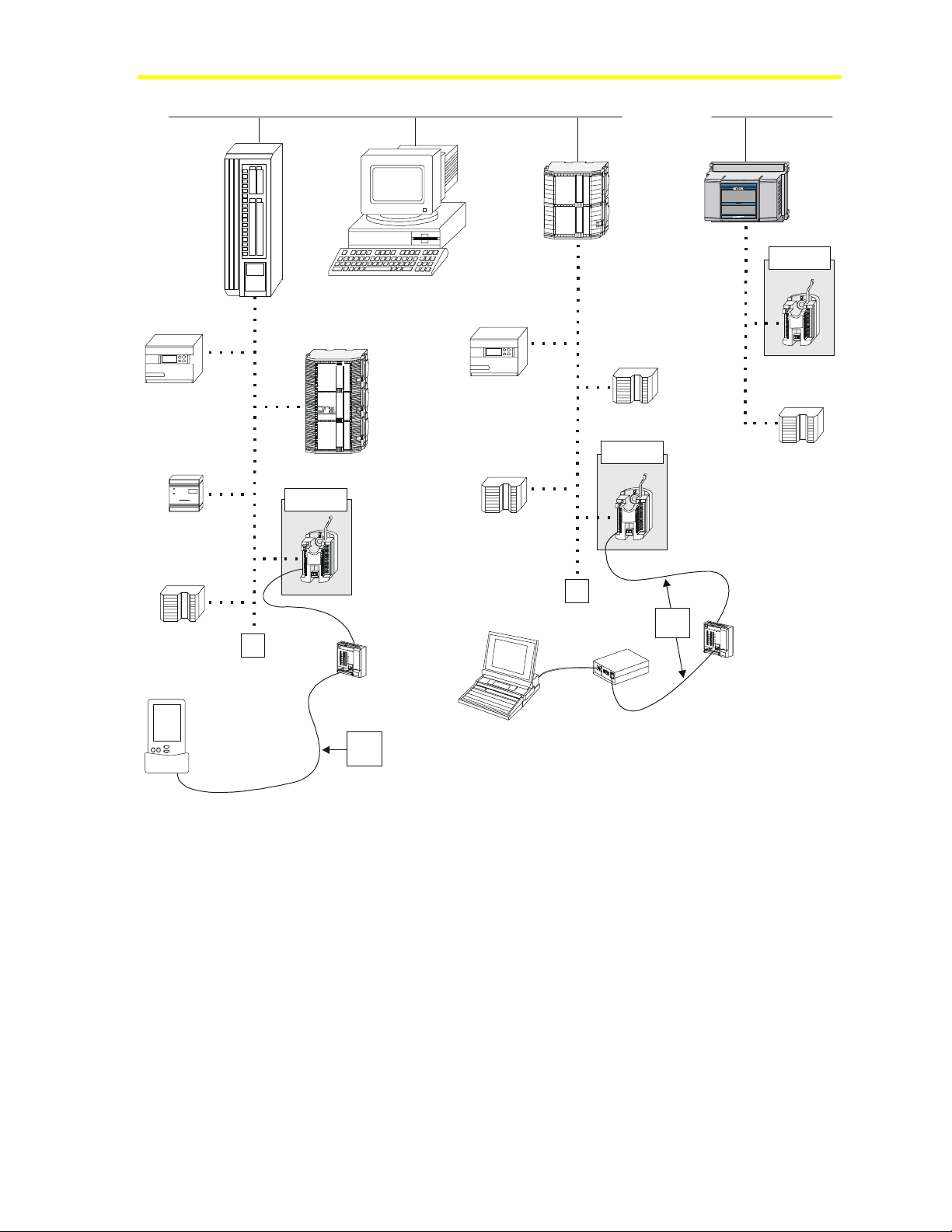
VMA1400 Series Overview and Engineering Guidelines Technical Bulletin 8
V
V
Ethernet LAN
Network
Control Unit
(NCU)
DX9100
TC9102
Unitary
Controller
(UNT)
Palm Compatible
Handheld Device
CVTPRO
Converter
Network
Control
Module
N30
N30
(NCM)
MA1400
Operator Workstation
DX9100
AHU
VAV
UNT
MA1400
UNT
VMA1400
N2
Zone
N2
CablePRO
Converter
Laptop
Room
Bus
Room
Sensor
Sensor
™
Zone
Bus
VMAMTSY6
Figure 2: VMA in Metasys Network Diagram
Page 9

VMA1400 Series Overview and Engineering Guidelines Technical Bulletin 9
Definition of Terms
Autocalibration
To correct for pressure sensor drifts over time, the VMA has an
Autocalibration mode that automatically compensates for temperature
and humidity effects.
N2 Switches
Single-pole, single-throw switches used to set the N2 address of a
controller.
Room Schedule
A set of information listing all parameters required in a room or zone.
Test and Balance (TAB)
Test and Balance (TAB) is a function performed to ensure the installed
system operates to design specifications. Balancing of the VMA zone
indicates whether the VAV terminal box is able to achieve
minimum/maximum airflow settings. TAB must also be performed for
the air handler and the air duct distribution to the VAV box.
Zones
When designing VMA systems, it is critical to establish zones
correctly to take full advantage of VMA’s exceptional accuracy and
rapid response capabilities.
The designer strives for the most uniform indoor environmental
conditions possible. A single thermostatic device (room sensor)
controls each area. Also, you may consider a zone any area where the
load is approximately the same for every square foot of floor space.
Heating, Ventilating, and Air Conditioning (HVAC) system zones fall
into two major categories: exterior zones and interior zones. Exterior
zones are spaces directly affected by outdoor weather conditions.
Interior zones are not influenced by heat losses or outdoor air
conditions. Interior zones usually have cooling or ventilation
requirements only.
Further division of interior/exterior zones is occasionally required to
accommodate different occupancy schedules and/or solar loads.
Variations in internal loading also dictate the selection of separate
zones. For example, in a restaurant, the kitchen has much different
heating and cooling requirements than the customer seating area.
Page 10

VMA1400 Series Overview and Engineering Guidelines Technical Bulletin 10
Room Sensor Placement
When considering room sensor placement for each zone:
• Verify that the room sensor is the correct one for the
application.
• Review architectural requirements such as furniture height and
location, aesthetics, and type of mounting. Wall plates are
required if mounting on a conduit handibox.
• Review room sensor location. The best room sensor location is
on an interior wall, about 1.5 m (5 feet) above the floor, out of
direct sunlight, out of the direct path of supply air from the
diffuser, away from heat sources, such as equipment, machines,
and perimeter radiation, and away from doors and other draft
sources. Local codes or disabilities act requirements
occasionally influence the actual mounting height.
• Do not locate a sensor near zone boundaries, where primary
influence is from an adjacent zone.
Pressure Independence
The pressure independent VMA employs patented self-tuning,
cascaded proportional/integral control loops. The zone temperature
loop samples space temperature and resets the airflow setpoint
between the minimum and maximum flow settings. Since inlet duct
static pressure influences the amount of air passing through the VAV
box, the VMA airflow loop samples airflow via a flow pickup in the
box inlet. It modulates the damper to control the flow. Thus, the
VAV box flow is independent of duct static pressure.
The engineering basis for this method of control is that the temperature
of a space with a constant load is linearly proportional to the flow of
conditioned air into the space. The engineer must accurately determine
the required maximum and minimum flow for each space based on
heating, cooling, and ventilation loads.
VMA Airflow Rate
The VMA determines airflow rate by dynamic pressure measurement.
The VMA contains a Differential Pressure Transducer (DPT) to sense
velocity pressure in pressure independent VAV applications.
The DPT is connected to the VAV box airflow pickups. It measures
velocity pressure and generates a proportional voltage signal. The
VMA reads voltage signal from the DPT and converts it to airflow in
cubic feet per minute (cfm), liters/second, or cubic meters/hour.
Calibration is not required, with the exception of zero calibration,
which the controller performs automatically as set in the configuration.
Page 11

VMA1400 Series Overview and Engineering Guidelines Technical Bulletin 11
The DPT provides maintenance-free performance within the control
range of 1 to 18 m/s (200 to 3500 feet per minute [fpm]) when used as
recommended.
Pressure independent VAV terminal boxes use an airflow pickup
device, which amplifies the airflow velocity pressure between 1.5 to
3 times (varies by manufacturer). The airflow velocity and the gain of
the airflow pickup produce an accurately measured pressure
difference.
The VMA Autocalibration function helps reduce the temperature
effect error by zeroing offset errors. As the ambient temperature
swings relative to the temperature at which the Autocalibration
occurred, an offset error occurs. In the worst case, the offset error
ranges up to ±0.179 Pascal per °C (±0.0004 inch w.c. per °F).
When calibration occurs, this error becomes zero.
The error envelope becomes smaller with increased airflow pickup
gain and with smaller ambient temperature deviations at the
transmitter location.
Power Source
You can use one 24 VAC power trunk to power multiple VMAs.
Transformers of up to 100 VA can be centrally located and the
secondary run can be without conduit (if allowed by local authority)
and without concern about polarity. When using a single transformer
to power multiple VMAs, use a wire gauge large enough to handle the
current and minimize the voltage drop. The voltage drop depends on
the current draw, wire gauge, and wire length. For more details about
transformer wiring and calculating the number of VMAs per
transformer, see the Mounting and Wiring Variable Air Volume
Modular Assembly (VMA) 1400 Series Controllers Technical Bulletin
(LIT-6363125).
Note: The 24 V power transformer must be UL/Canadian
Standards Association (CSA) listed as NEC Class 2 Power Limited.
See NEC Article 725/Class 2 (30 VRMS maximum) and
(100 VA maximum).
Page 12

VMA1400 Series Overview and Engineering Guidelines Technical Bulletin 12
N2 Bus Rules
The N2 Bus is the interface between a supervisory controller
(Metasys Network Control Module [NCM] or N30) and all application
specific controllers in a Metasys Network. The VMA is
self-terminating in that there are no End-of-Line (EOL) jumpers to set.
However, you must set one EOL for each N2 Bus, usually at the NCM
or N30. Table 2 summarizes the rules for installing the N2 Bus.
Table 2: N2 Bus Rules
Category Rules/Maximums Allowed
General
Maximum Number of Devices
Line Length and Type
Terminations
* Add repeater after 49 devices. Count each repeater as one device.
Only one NCM or N30 per N2 Bus
Only daisy-chained devices
100 devices per NCM or 50 devices per N30
50 devices per repeater*
Two repeaters cascaded
1500 m (5000 feet) between repeaters
4500 m (15,000 feet) maximum length
(3 segments of 1500 m [5000 feet] each)
0.6 mm (24 American Wire Gauge [AWG])
twisted pair minimum
(stranded 0.8 mm [22 AWG] twisted pair or
heavier recommended)
Two EOL devices per each segment that is
longer than 100 m (330 ft)
One EOL device at the controller for all
segments regardless of length (required)
Page 13

VMA1400 Series Overview and Engineering Guidelines Technical Bulletin 13
Inputs and Outputs
For specific input/output range, cable length, wire size issues, refer to
the Mounting and Wiring Variable Air Volume Modular Assembly
(VMA) 1400 Series Controllers Technical Bulletin (LIT-6363125).
Note: All terminals are spade lug type except the N2 terminals,
which are removable screw terminals. Optional two-, three-, or
four-position kits (available for order) convert the spade lugs to
removable screw terminals.
Table 3: Inputs and Outputs
Input/Output Description
Analog Inputs
Binary Inputs
Analog
Outputs
Binary
Outputs
There are two external and one internal analog i nputs on the VMA1410 and four external
and one internal analog inputs on the VMA1420 and 1430. They are prese t for either
temperature/setpoint or voltage. There are no jumpers to set. Shielding is not required, but if
used, earth ground the shield only at the VMA. You may use 0.6 mm (24 AWG) twisted pair
wire; however, this reduces the allowable wire length due to the resistance for Nickel (Ni),
Platinum (Pt), or Silicon (Si) sensors. To minimize sensor error caused by field wiring, the
total resistance of the nickel, silicon, or platinum resistive sensor wiring should be less than
3 ohms. The NTC sensor accepts a larger wire resistance. This wiring error effect can be
corrected through HVAC PRO software in the VMAs analog input.
Do not share the temperature/setpoint common wire (COM) with any other sensors,
transmitters, or the Zone Bus. The maximum voltage drop on the common wire must be less
than 1 mV.
There are three dry contact binary inputs on the VMA. An override button on the room
sensor initiates a Temporary Occupancy or Time Override mode of op eration when pressed.
When using the TE-6700 or TE-7000 (Europe only) sensor, T empOcc shorts BI-1 directl y.
Hold for 2.0 seconds.
The binary inputs on the VMA are inactive when open. They are active when you appl y a
contact closure to binary input common (COM).
There are two analog outputs on the VMA1420 and VMA1430. The VMA1410 h as no
analog outputs. The load connects between the analog output and analog output common
(COM) terminals. Each output generates a proportional voltage output of 0 to 10 VDC. The
maximum load for each output is 10 mA with a minimum load resistance of 1000 ohms.
Note that two analog outputs are available on the VMA1430 for proportional reheat valves
or a proportional damper actuator.
The VMA1410 has no external binary outputs. The VMA1420 and VMA1430 have
five external binary outputs. The damper actuator wires internally to the VMA1410 and
VMA1420. Each load connects between the BO terminal and BCOM common terminal.
These outputs switch the transformer’s low side to the output allowing the relays, actuators,
or transformers to be earth grounded through Terminal 1 when needed to meet codes.
A floating/3-wire (incremental) actuator wires externally to two of the five BOs on the
VMA1430. There are only three BOs remaining for fan, box heating, supplemental heating,
and lighting.
Page 14

VMA1400 Series Overview and Engineering Guidelines Technical Bulletin 14
Zone Bus
The Zone Bus is a 2-wire communications bus that allows a computer
to commission and balance the VMA’s database. The computer must
have the proper software and must connect through the CablePRO
(AS-CBLPRO or IU-9100 in Europe) or CVTPRO (ASCVTPROx00-x) converter and the room sensor. The VMA also
supplies 15 VDC through the Zone Bus connector to power the
CablePRO or CVTPRO converter.
Note: The VMA supplies 15 VDC instead of 24 VAC supplied by
other Application Specific Controller (ASC) devices. The Zone Bus
does not function properly if connected to 24 VAC on the VMA.
Table 4: Zone Bus Specifications
Feature Specification
Type
Speed
Recommended Cable
Type
Maximum Bus Length
Single Ended
Differential
Voltages
Single Ended
Logic High Voltage
Logic Low Voltage
Differential
Transmit
Receive
Data Transmission
Isolation
Multi-drop serial communications bus, single ended
(North America) or differential (Europe)
1200 baud (bits per second)
2
1.5 mm
(Beldon 8760)
or
0.6 mm (24 AWG) without shield (unshielded
telephone cable)
150 meters (500 feet) with 1.5 mm
15 meters (50 feet) with 0.6 mm (24 AWG) cable
1500 meter (5000 feet) of 0.6 mm - 1.5 mm
(18-24 AWG) cable
4 VDC minimum (approximately)
1 VDC maximum (approximately)
±5 VDC
±0.2 VDC
1 Start Bit (low level)
8 Data Bits (least significant bit first)
1 Stop Bit (high level)
Isolated from 24 VAC, BOs, and N2 Bus
(18 AWG) with or without shield
2
(18 AWG) cable
2
Note: Do not share the Zone Bus common wire with any other
sensor or transmitter, as doing so can cause the VMA to misread the
sensor value, resulting in poor control.
Page 15

VMA1400 Series Overview and Engineering Guidelines Technical Bulletin 15
CablePRO
CablePRO (AS-CBLPRO) is an interface device that is used between a
computer or Palm™ compatible handheld device and the VMA. Use
CablePRO for box balancing or commissioning via the Zone Bus
communication port on the room sensor.
When used with a VMA, the CablePRO is strictly an electrical
interface between the serial RS-232 port of the computer and the
VMA. CablePRO operates on 15 VDC drawn from a VMA and
provided through the Zone Bus. The data rate on both the RS-232 and
the Zone Bus is 1200 baud.
The VMA connects to the RS-232 COM port of the computer via a
DB9 or DB25 connector supplied with the CablePRO.
The diagnostic LEDs on the CablePRO indicate normal Zone Bus
communications. The LEDs flash only when the VMA is transmitting
or receiving data.
Refer to the Auxiliary Gear Technical Bulletin (LIT-6363080) for
more information on the CablePRO.
CVTPRO
CVTPRO (AS-CVTPROx00-x) is a Zone Bus/N2 Bus interface device
that is used between a computer or Palm compatible handheld device
and the VMA. Use CVTPRO for box balancing or commissioning via
the Zone Bus communication port.
When used with a VMA, the CVTPRO is strictly an electrical interface
between the serial RS-232 port of the Palm compatible handheld
device and the Zone Bus. CVTPRO operates on 15 VDC, drawn from
a VMA through the Zone Bus phone jack. The data rate on both the
RS-232 and the Zone Bus is 1200 baud.
Refer to the Auxiliary Gear Technical Bulletin (LIT-6363080) for
more information on the CVTPRO. For additional information on
installing the AS-CVTPRO300-1 and ASCVTPRO400-1, refer to the
AS-CVTPRO300-1 and AS-CVTPRO400-1 Zone Bus/N2 Bus Interface
Converters Installation Instructions (Part No. 24-10158-0).
Page 16

VMA1400 Series Overview and Engineering Guidelines Technical Bulletin 16
Related Documentation
Table 5 lists related VMA documentation.
Table 5: Related Documentation
For Information on This Use This Document:
Sales and Marketing Information
Downloading and
Commissioning Details
N30 Networking
Original Equipment Manufacturer
(OEM) Issues
Configuration Choice
Using VMA Balancing Tool (VBT)
Software
Connecting Using CablePRO or
CVTPRO
Variable Air Volume Modular Assembly (VMA) 1400 Series Product
Bulletin (LIT-635058)
HVAC PRO User’s Guide
N30 Supervisory Controller Networking Technical Bulletin
(LIT-6891300)
Appendix B: VAV Controller Flow Calculation Constants Application
Note (LIT-6375185)
Variable Air Volume Modular Assembly (VMA) 1400 Series Application
Note (LIT-6375125)
Using the VMA1400 Balancing Tool (VBT) Software Technical Bulletin
(LIT-6363092)
Auxiliary Gear Technical Bulletin (LIT-6363080)
Page 17

VMA1400 Series Overview and Engineering Guidelines Technical Bulletin 17
Application Examples
Note: The examples in this document do not reflect all of the
possible questions and answers. These examples provide a basic
overview of wiring locations you might expect to see. They do not
define all available applications.
Single Duct Application Example 1
Table 6: Single Duct Example 1 Questions
HVAC PRO Software Questions Configuration Selections
VAV Box Type
Fan Type (R2)
Baseboard Heat Type
Box Heat Type (R3 and R4)
Lighting (R1)
R4
R3
Pressure Independent, Single Duct
Series/On-Off
None
2-stages
Start Stop Output (as shown in
Figure 4)
Plenum
Supply
R1
H
T
G
DPT1 DA1
C1
R2
TE1
Discharge
Sample1
Figure 3: Single Duct Example 1 Mechanical Flow Diagram
Table 7: Single Duct Example 1 Bill of Materials
Component Description Part Number
C1, DPT1, DA1
TE1
R1
R2
R3, R4
* Box OEM manufacturers typically furnish fan relays and electric heat relays.
VMA AP-VMA1420-0
Temperature Sensor and Setpoint TE-6700 Series
Lighting Relay GE-RR7
Fan *
Reheat Relays *
Page 18

VMA1400 Series Overview and Engineering Guidelines Technical Bulletin 18
1
le
)
e
r
g
u
in
s
b
s
u
e
r
T
p
ic
l
t
ia
a
t
n
m
e
u
r
e
e
n
f
if
P
O
L
)
d
I
e
H
R
(
p
o
t
S
W
d
C
n
E
lt
o
w
B
e
r
r
c
le
p
S
u
t
o
e
S
C
r
le
p
u
o
C
d
(
p
d
W
o
n
t
C
E
S
C
if
e
d
o
C
C
E
N
1
-
I
B
)
8
1
(
C
A
V
4
2
)
1
(
n
a
C
h
y
r
A
T
a
V
e
r
0
im
o
r
5
P
1
M
r
e
r
m
r
e
o
f
w
s
o
n
P
a
r
T
M
M
2
-
O
O
I
B
C
C
)
)
)
0
1
9
2
2
1
(
(
(
.
d
n
C
G
l)
A
h
t
a
V
r
n
a
4
io
2
E
t
p
)
)
2
O
3
(
(
(
C
A
V
4
2
y
r
a
im
r
P
*
C
C
D
D
V
V
M
3
5
-
O
I
1
+
B
C
)
)
)
4
2
3
2
2
2
(
(
(
*
*
M
1
-
O
O
C
B
B
)
)
4
5
(
(
C
C
A
A
V
V
4
4
2
2
2
R
y
la
e
R
n
a
F
M
1
5
1
+
)
5
2
(
*
2
O
B
)
6
(
3
R
y
la
e
R
1
e
g
a
t
S
-2
-
O
I
I
A
A
C
)
)
)
8
6
7
2
2
2
(
(
(
*
*
M
O
C
B
)
7
(
*
M
4
*
-
3
O
O
O
C
B
B
)
B
)
)
0
8
9
1
(
(
(
C
A
n
V
O
4
2
4
R
y
la
e
R
2
e
g
a
t
S
5
4
1
8
*
*
*
M
M
3
4
-
-
O
O
I
I
C
C
A
)
9
2
(
1
R
y
la
e
R
g
in
t
h
ig
L
A
)
)
)
0
1
2
3
3
3
(
(
(
*
*
*
*
M
M
5
1
-
-
O
O
C
O
C
B
)
1
1
(
O
B
B
A
)
)
)
3
4
2
1
1
1
(
(
(
ff
O
*
*
0
0
7
6
E
T
*
M
+
-
O
B
B
C
Z
Z
)
)
)
3
4
5
3
3
3
(
(
(
2
+
N
2
-
N
F
E
R
H
D
L
S
*
*
*
2
M
M
O
O
O
C
C
A
)
)
)
7
6
5
1
1
1
(
(
(
n
o
i
t
c
A
l
a
u
s
i
V
D
E
L
ly
n
o
0
3
4
1
/
0
2
4
1
A
M
V
n
o
d
e
d
lu
c
n
I
*
s
n
n
io
t
io
a
t
a
ic
n
liz
u
ia
m
it
m
in
o
g
c
r
in
r
e
t
u
f
A
D
g
in
h
e
t
s
a
la
r
t
e
f
a
s
n
o
p
s
e
R
d
r
s
n
la
e
o
u
c
h
g
s
e
e
s
r
la
Ir
1
F
3
2
N
O
1
h
0
c
0
it
7
w
6
-
S
E
P
T
I
r
D
o
f
d
e
n
r
r
io
e
it
f
s
e
o
r
P
P
*
*
d
a
lo
n
w
o
d
e
d
d
e
o
h
c
lis
s
b
d
a
e
t
e
s
N
e
g
in
r
h
e
s
p
s
la
e
s
d
f
e
n
id
im
o
t
p
im
c
t
a
0
e
2
R
s
4
p
m
a
x
e
le
g
in
S
M
s
u
C
B
N
2
o
T
N
G
W
A
8
1
-
4
2
ld
ie
h
S
2
N
l
a
n
io
t
p
O
d
e
r
t
o
r
o
r
h
e
s
w
o
V
p
5
o
1
+
N
d
n
o
c
e
lit
s
t
r
o
e
N
p
e
t
ic
x
v
e
e
N
D
o
2
T
N
Figure 4: Single Duct Fan-Powered Box Example 1
Page 19

VMA1400 Series Overview and Engineering Guidelines Technical Bulletin 19
Single Duct Application Example 2
Table 8 illustrates the selections made through HVAC PRO software
for this example.
Table 8: Example 2 Questions
HVAC PRO Software Questions Configuration Selections
Control Strategy
Supply Damper Actuator (DA1)
Fan Type (R)
Baseboard Heat Type (VA2)
Box Heat Type (VA1)
Warmup Initiation
Lighting Integration
Pressure Independent, Single Duct
Floating/3-wire
Parallel Fan Temperature Controlled
Analog Output Valve
Floating/3-wire
Supply Air Temp Via a Hardware Input
No
R
Plenum
H
Supply
TE2
DPT1 DA1
C1
TE1
T
G
VA1
Discharge
VA2
B
A
S
E
B
D
Sample3
Figure 5: Single Duct Example 2 Mechanical Flow Diagram
Table 9: Single Duct Example 2 Bill of Materials
Component Description Part Number
C1, DPT1
DA1
TE1
TE2
VA1
VA2
R
* Box OEM manufacturers typically furnish fan relays and electric heat relays.
VMA AS-VMA1430-0
Damper Actuator Integrated with VAV box
Zone Temperature Sensor TMZ1600
Supply Air Temperature Sensor TE-6311P-1
Valve Actuator Box Heat VA-8020-1
Baseboard Heat Valve Actuator VA-8052
Fan *
Page 20

VMA1400 Series Overview and Engineering Guidelines Technical Bulletin 20
)
e
r
g
u
in
s
b
s
u
e
r
T
p
ic
l
t
ia
a
t
n
m
e
u
r
e
O
L
)
d
I
e
H
R
(
e
n
iff
P
d
(
0
*
0
g
6
1
in
ir
Z
M
W
T
M
1
-
O
I
C
B
)
)
9
8
1
1
(
(
C
C
A
A
V
V
4
4
2
2
)
)
2
1
(
(
if
n
e
a
d
C
h
o
y
r
A
C
T
a
V
e
r
C
0
im
o
E
r
5
P
M
1
N
r
e
r
m
r
e
o
w
f
s
o
n
P
a
r
T
6
5
3
C
C
D
D
V
V
M
M
3
2
-
-
O
O
I
I
C
C
B
B
)
)
)
)
3
1
2
0
2
2
2
2
(
(
(
(
.
d
n
)
G
M
d
1
h
e
-
t
O
r
s
C
O
a
U
B
B
E
t
o
)
)
)
5
4
N
3
(
(
(
(
1
A
D
r
r
e
o
t
p
a
m
u
t
a
c
D
C
A
V
4
2
y
r
a
im
r
P
A
M
M
1
5
+1
)
4
2
(
2
O
B
)
6
(
2
5
-
O
O
I-
I
1
+
C
)
5
2
(
M
O
C
B
)
7
(
R
n
a
F
C
A
A
)
)
)
)
6
7
8
9
2
2
2
2
(
(
(
(
M
M
4
-
O
3
O
O
C
C
O
B
B
B
B
)
)
)
0
)
1
1
9
1
8
(
(
(
(
1
A
V
t
x
a
o
e
B
H
C
A
V
M
2
E
T
8
M
M
3
-
I
A
)
0
3
(
-5
O
B
)
2
1
(
2
4
O
C
+
4
-
O
O
B-
B
I
C
)
1
3
(
M
O
C
B
)
3
1
(
Z
Z
C
A
)
)
)
)
2
5
4
3
3
3
3
3
(
(
(
(
2
+
N
2
-
N
F
E
R
H
D
S
L
2
1
M
M
-
O
O
O
O
C
C
A
A
)
)
)
)
7
6
5
4
1
1
1
1
(
(
(
(
M
O
+
C
2
A
V
t
d
a
r
e
a
o
H
b
e
s
a
B
.
C
d
A
e
t
V
c
e
4
n
2
n
r
e
o
o
h
c
t
C
f
e
o
D
b
)
V
n
ly
a
5
p
c
1
p
+
0
u
r
0
S
e
6
(
h
1
5
it
Z
e
in
M
o
T
t
P
*
d
e
t
r
s
n
n
io
t
io
a
t
a
ic
n
liz
u
ia
d
m
it
e
m
h
in
o
n
o
i
t
c
A
e
s
n
o
p
s
e
R
l
a
u
s
i
V
D
E
L
lis
g
c
b
r
in
a
r
e
t
t
u
f
s
D
A
e
s
e
t
e
a
r
im
t
d
n
4
o
g
c
e
in
s
h
s
1
d
t
la
f
n
a
r
o
s
c
la
e
e
u
h
s
g
s
r
e
r
la
e
r
I
p
F
o
d
h
a
s
lo
V
n
5
w
1
o
+
d
r
e
o
d
r
o
e
c
w
s
o
d
p
e
e
o
N
N
s
e
im
t
0
2
g
in
h
d
s
n
o
la
f
c
e
id
lit
s
p
t
r
a
o
e
R
p
N
2
le
p
m
a
x
e
le
g
in
M
s
S
u
C
B
N
2
N
To
G
W
A
8
1
-
4
2
ld
ie
h
S
2
N
l
a
n
io
t
p
O
e
t
ic
x
v
e
e
N
D
o
2
T
N
Figure 6: Single Duct Fan-Powered Box Example 2
Page 21

VMA1400 Series Overview and Engineering Guidelines Technical Bulletin 21
Single Duct Supply/Exhaust Application Example
Table 10 illustrates the selections made through HVAC PRO software
for this example.
Table 10: Example Questions
HVAC PRO Software Questions Configuration Selections
Control Strategy
Supply Actuator
Fan Type
Exhaust Actuator (DA2)
Box Heat Type (VA1)
Baseboard Heat Type
Lighting Integration
Pressure Independent, Supply/Exhaust
VMA Integrated Actuator
None
Position Adjust Output (3-wire/floating)
Analog Output
None
None
DPT2
DA2
Exhaust Air
H
Supply Air to Zone
DA1
DPT1
C1
T
G
VA 1
from Zone
TE1
supplyexh
Figure 7: Single Duct Supply/Exhaust Example Mechanical Flow Diagram
Table 11: Example Bill of Materials
Component Description Part Number
C1, DPT1, DA1
DPT2, DA2
VA1
TE1
VMA AP-VMA1420-0
External Actuator and Velocity
Pressure Sensor
Value Actuator Box Heat VA-8020-1
Temperature Sensor and Setpoint TE-6700 Series
M9104-AGS-2N
Page 22

VMA1400 Series Overview and Engineering Guidelines Technical Bulletin 22
Single Duct Supply/Exhaust with BO Solenoid Application
Example
Table 12 illustrates the selections made through HVAC PRO for
Windows operating system for this example.
Note: This example only applies to HVAC PRO 8.05 or later.
Table 12: Example Questions
HVAC PRO Software Questions Configuration Selections
Control Strategy
Supply Actuator (DA1)
Fan Type
Exhaust Actuator (DA2)
Box Heat Type (VA1)
Baseboard Heat Type
Lighting Integration
Pressure Independent, Supply/Exhaust
with BO for Autocalibration Solenoid
VMA Integrated Actuator
None
Position Adjust Output (3-wire/floating)
Analog Output
None
None
Supply
Air
Exhaust Air
nc
no
SOL1
DA2
DPT2
c
H
T
G
DA1
DPT1
c
C1
VA 1
nc
SOL2
TE1
no
to Zone
supplyexhBO
from
Zone
Figure 8: Single Duct Supply/Exhaust with BO Solenoid Example Mechanical Flow Diagram
Table 13: Example Bill of Materials
Component Description Part Number
C1, DPT1, DA1
DPT2, DA2
SOL1, SOL2
VA1
TE1
* Part is available from Kele & Associates. For current information, consult the Web
site at www.kele.com.
VMA AP-VMA1420-0
External Actuator and Velocity
M9104-AGS-2N
Pressure Sensor
MAC 3-Way Solenoid Air Valves 35A-FW-24VAC*
Value Actuator Box Heat VA-8020-1
Temperature Sensor and Setpoint TE-6700 Series
Page 23

VMA1400 Series Overview and Engineering Guidelines Technical Bulletin 23
le
p
m
0
0
5
4
)
e
r
g
u
in
s
b
s
u
e
r
T
p
l
ic
t
ia
a
t
n
m
e
u
r
e
e
n
iff
P
d
O
(
L
)
d
I
e
H
R
(
p
o
t
S
W
d
C
n
E
lt
o
w
B
e
r
r
c
le
p
S
u
t
o
e
S
C
r
le
p
u
o
C
p
d
W
o
n
t
C
E
S
C
if
e
d
o
C
C
E
N
1
-
I
B
)
8
1
(
C
A
V
4
2
)
1
(
n
a
C
h
y
r
T
A
a
V
e
r
0
im
o
r
5
M
1
P
r
e
r
m
r
e
o
f
w
s
o
n
P
a
r
T
M
M
2
O
O
IB
C
C
)
)
)
0
1
9
2
2
1
(
(
(
.
d
n
C
G
l)
A
h
t
a
V
r
n
a
4
io
2
E
t
p
)
)
2
O
3
(
(
(
2
L
O
S
C
A
V
4
2
y
r
a
im
r
P
*
C
C
D
D
V
V
M
3
-
O
I
B
C
)
)
2
3
2
2
(
(
*
*
M
1
-
O
O
C
B
B
)
)
4
5
(
(
1
L
O
S
s
id
o
n
le
o
S
M
1
5
5
-
O
I
1
1
C
+
+
A
)
)
)
)
7
6
5
4
2
2
2
2
(
(
(
(
*
*
*
2
O
B
)
6
(
M
M
*
3
O
O
C
C
O
B
B
B
)
)
)
7
8
9
(
(
(
2
A
D
r
r
o
e
t
p
a
m
tu
a
c
D
A
1
8
*
*
M
M
3
-
-2
I
A
)
8
2
(
O
O
I
C
C
A
)
)
)
1
0
9
3
3
2
(
(
(
*
*
*
*
4
O
B
)
0
1
(
M
M
5
-
O
O
C
O
C
B
B
B
)
)
)
3
2
1
1
1
1
(
(
(
t
s
ly
u
n
a
o
h
x
le
E
/
p
ly
m
p
a
p
x
u
E
S
7
6
E
T
*
*
M
-
+
4
-
O
B
B
I
A
)
2
3
(
Z
Z
C
)
)
)
5
4
3
3
3
3
(
(
(
2
+
N
2
-
N
F
E
R
H
D
S
L
*
*
*
2
1
M
-
O
O
O
C
A
A
)
)
)
6
5
4
1
1
1
(
(
(
1
A
V
e
r
r
u
o
s
s
s
n
e
r
e
P
S
2
T
P
D
.
ly
n
o
0
3
4
n
1
o
/
*
M
O
C
)
7
1
(
n
io
t
a
liz
ia
it
in
n
g
o
in
i
r
t
u
c
A
D
e
t
l
a
a
r
t
e
u
a
s
d
s
n
s
i
n
o
e
o
V
c
h
p
s
e
s
D
s
e
E
la
R
L
F
1
0
d
2
e
4
d
1
lu
A
c
M
n
I
V
*
d
s
a
n
lo
io
t
n
a
w
ic
o
n
d
u
e
d
m
d
e
o
m
h
c
o
lis
s
c
b
d
r
e
e
ta
e
ft
s
N
e
A
g
in
g
h
s
in
r
h
la
e
f
s
r
la
u
g
e
r
r
I
p
s
la
f
e
s
d
e
n
id
o
tim
p
im
c
t
a
0
e
2
R
s
4
a
x
e
id
o
n
le
o
s
O
B
ld
ie
h
S
2
N
l
a
n
io
t
p
O
d
e
r
t
o
r
o
r
h
e
s
w
o
V
p
5
o
1
+
N
d
n
o
c
e
lit
s
t
r
o
e
N
p
M
s
u
C
B
N
2
o
T
N
G
W
A
8
1
-
4
2
e
t
ic
x
v
e
e
N
D
o
2
T
N
Figure 9: Single Duct Supply/Exhaust with BO Solenoid Example
Page 24

VMA1400 Series Overview and Engineering Guidelines Technical Bulletin 24
Dual Duct Application Example
Table 14 illustrates the selections made through HVAC PRO software
for this example.
Note: This example only applies to HVAC PRO 8.0 or later.
Table 14: Example Questions
HVAC PRO Software Questions Configuration Selections
Control Strategy
Discharge Air Sensor (TE2)
Cold Deck Actuator
Hot Deck Actuator (DA2)
Flow Sensor Locations (DPT1 and
DPT2)
Baseboard Heat Type
Lighting Integration
Pressure Independent – Variable Box
Flow, Dual Duct
Yes
VMA Integrated Actuator
Position Adjust Output (3-wire/floating)
Hot and Cold Deck Flow
None
None
DPT2
Da2
Hot Deck
Supply
Discharge
Cold Deck
Supply
Da1
DPT1
C1
Te2
TE1
Figure 10: Dual Duct Example Mechanical Flow Diagram
Table 15: Example 2 Bill of Materials
Component Description Part Number
C1, DPT1, DA1
DPT2, DA2
TE1
TE2
VMA AP-VMA1420-0
External Actuator and Velocity
Pressure Sensor
Temperature Sensor and Setpoint TE-6700 Series
Discharge Air Temperature Sensor TE-6300 Series
M9104-AGS-2N
DD_Example
Page 25

VMA1400 Series Overview and Engineering Guidelines Technical Bulletin 25
le
p
m
0
0
5
4
)
e
r
g
u
in
s
b
s
u
e
r
T
p
ic
l
t
ia
a
t
n
m
e
u
r
e
e
n
iff
P
d
O
(
L
)
d
I
e
H
R
(
p
o
t
S
W
d
C
n
E
lt
o
w
B
e
r
r
c
le
p
S
u
t
o
e
S
C
r
le
p
u
o
C
p
d
W
o
n
t
C
E
S
C
if
n
e
a
d
h
o
T
C
e
r
C
o
E
N
M
M
2
1
-
-
O
I
I
C
B
B
)
)
)
9
0
8
1
2
1
(
(
(
.
d
n
G
C
C
l)
A
A
h
t
a
V
V
r
n
a
4
4
io
E
2
2
t
p
)
)
)
O
3
2
1
(
(
(
(
C
y
r
A
a
V
0
im
r
5
P
1
r
e
r
m
r
e
o
f
w
s
o
n
P
a
r
T
2
L
O
S
C
A
V
4
2
y
r
a
im
r
P
*
C
C
D
D
V
V
M
M
3
5
-
O
O
I
1
C
B
C
+
)
)
)
)
1
2
3
4
2
2
2
2
(
(
(
(
*
*
*
M
2
1
-
-
O
O
O
C
B
B
B
)
)
)
6
4
5
(
(
(
1
L
O
S
s
id
o
n
le
o
S
M
1
5
-
O
I
1
C
+
A
)
)
)
7
6
5
2
2
2
(
(
(
*
M
*
3
O
O
C
B
B
)
)
8
7
(
(
2
A
D
r
r
o
e
t
p
a
u
m
t
a
c
D
A
1
8
*
*
M
M
3
-
-2
I
A
)
8
2
(
*
M
O
C
B
)
9
(
O
O
I
C
C
A
)
)
)
1
9
0
3
2
3
(
(
(
*
*
*
*
M
M
4
5
-
-
O
O
O
O
C
C
B
B
B
B
)
)
)
)
0
2
3
1
1
1
1
(
1
(
(
(
t
s
ly
u
n
a
o
h
x
le
E
/
p
ly
m
p
a
p
x
u
E
S
7
6
E
T
*
*
M
+
4
-
O
B
I
C
Z
A
)
)
)
3
4
2
3
3
3
(
(
(
2
+
N
2
-
N
F
E
R
H
D
L
S
*
*
*
1
2
M
-
-
O
O
O
C
A
A
)
)
)
4
5
6
1
1
1
(
(
(
1
A
V
e
r
r
u
o
s
s
s
n
e
e
r
S
P
2
T
P
D
B
Z
)
5
3
(
.
ly
n
o
0
3
4
n
1
o
/
*
M
O
C
)
7
1
(
n
io
t
a
liz
ia
it
in
n
g
o
i
in
t
r
c
u
A
D
e
t
l
a
a
t
r
e
u
a
s
d
s
n
s
i
n
o
e
o
V
h
c
p
s
s
D
e
s
e
E
la
L
R
F
1
0
d
2
e
4
d
1
lu
A
c
n
M
I
*
V
d
s
a
n
lo
io
t
n
a
w
ic
o
n
d
u
e
d
m
d
e
o
m
h
c
o
lis
c
s
b
d
r
e
e
ta
e
ft
s
A
e
N
g
in
g
h
s
in
r
h
e
fla
s
r
la
u
g
e
r
r
I
p
s
la
f
s
e
d
e
n
id
im
o
t
p
im
c
t
a
0
e
s
4
R
2
a
x
e
id
o
n
le
o
s
O
B
M
C
N
o
T
ld
ie
h
S
2
N
l
a
n
io
t
p
O
d
e
r
t
o
r
o
r
h
e
s
w
o
V
p
5
o
1
+
N
d
n
o
c
e
s
lit
t
r
o
e
p
N
s
u
B
2
N
G
W
A
8
1
-
4
2
e
t
ic
x
v
e
e
N
D
o
2
T
N
Figure 11: Dual Duct Example
Page 26

VMA1400 Series Overview and Engineering Guidelines Technical Bulletin 26
Reference Information
VMA Parts List
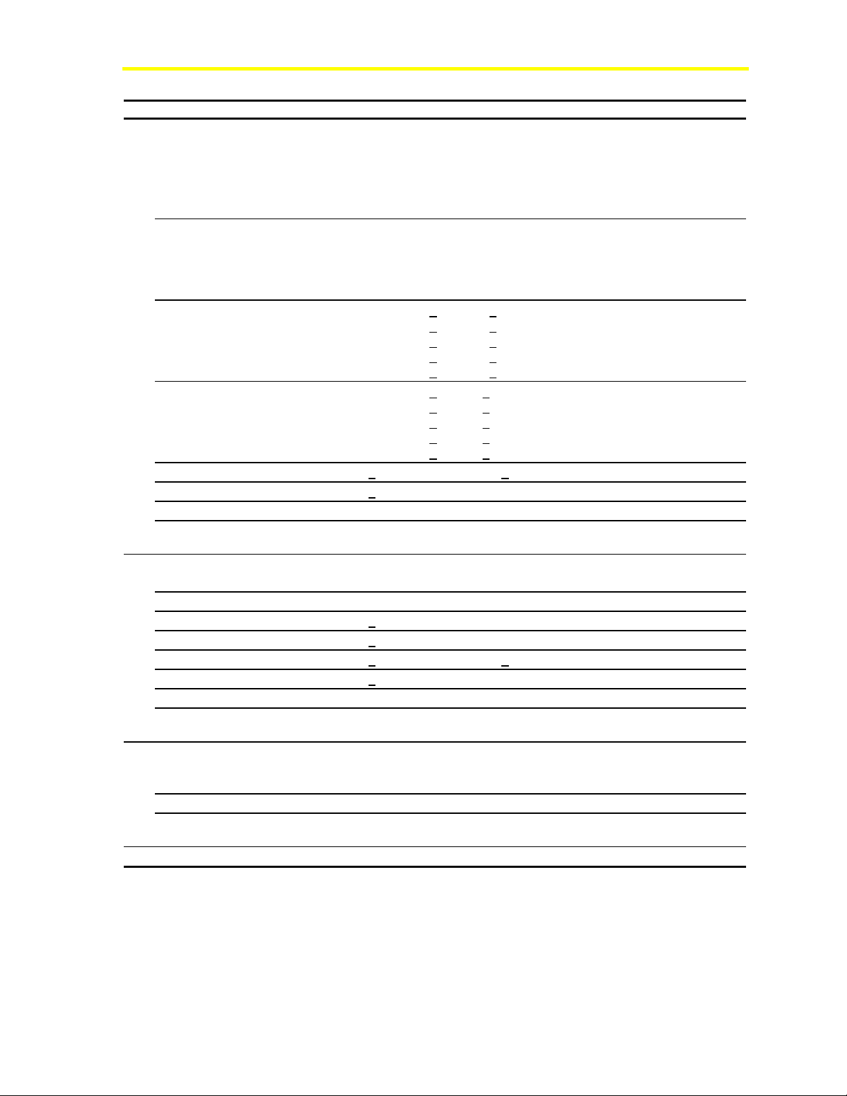
Table 16: Available VMA Models
Inputs/Outputs Points Rating VMA1410
(Cooling
Only)
Analog Inputs
Zone Temperature
Zone Setpoint
Humidity, Dewpoint,
Sideloop, or Velocity
Pressure
Supply Air Temperature
or Supplemental Heat
Temperature
Velocity Pressure
Binary Inputs
Temporary Occupied/
Standby
Occupied
Off or Window or
Shutdown
Analog Outputs
Proportional Heat
Binary Outputs
Lights
Fan
Box Heat--Valve or 1-3
stage Electric
Supplemental Heat--
Valve or Single Stage
Electric Box Heat
External Damper
Actuator
Stepper Motor with Position
Feedback
AI-1 1 K Ni, Si, or Pt or
2.25 K NTC
AI-2 1.6 K ohm
Potentiometer
AI-3 0-10 VDC
AI-4 1 K Ni, Si, or Pt or
2.25 K NTC
Internal 0-1.5 in. w.c./
0-374 pa
BI-1 Dry contact
BI-2 Dry contact
BI-3 Dry contact
AO-1 0-10 VDC @ 10 mA
AO-2 0-10 VDC @ 10 mA
BO-1 to
BO-5
Internal 2-phase Stepper
24 VAC Triac @
0.5 A each
VMA1420
(Cooling
w/Reheat)
VMA1430
Page 27

VMA1400 Series Overview and Engineering Guidelines Technical Bulletin 27
Specifications
Table 17: Specifications
Feature Specification
Product Name
Product Code
Number
Single Unit
Bulk Pack
Buy American
Supply Voltage
Optional Fuse Current
Power Consumption
Ambient Operating
Conditions
Ambient Storage
Conditions
Terminations
Serial Interfaces
N2 Controller
Addressing
Communications Bus
Mounting
Housing
Dimensions
(L x W x H)
Actuator Torque
Shipping Weight
Electrical Inputs
Velocity Pressure
Outputs
Continued on next page . . .
Variable Air Volume Modular Assembly (VMA)
Cooling Only
Models:
AP-VMA1410-0
AP-VMA1410-0D
AP-VMA1410-0G
20-30 VAC at 50 or 60 Hz
0.6 ampere for VMA1410; 2.0 ampere for VMA1420; 1.2 ampere for VMA1430
VMA1410/1420: 10 VA maximum (relay and valve requirements not included)
VMA1430: 3 VA maximum (damper actuator, relay, and valve requirements
not included)
0 to 50°C (32 to 122°F)
-40 to 70°C (-40 to 158°F)
6.3-mm (1/4-in.) spade lugs (Communication has screw terminals.)
N2 Bus and Zone Bus
DIP switch set (1-253) Addresses 254 and 255 are reserved. Software addressable
with the HVAC PRO program Release 7.02 or later, or the VBT program
N2 between VMA and NCM/N30 (3-wire). Zone Bus between VMA and room sensor
(8-pin phone jack or wire to spade lugs or optional plug-on terminals)
One screw (included) mounts the VMA1410/1420 to the VAV box. One screw
attaches damper shaft to the actuator, 8-mm (5/16-in.) square head set screw with
44 N.m (375 lb.in) of axial holding power for up to 13-mm (1/2-in.) round damper
shafts. Minimum damper shaft length is 44.5 mm (1-3/4 in.). Use two screws
(included) to mount the VMA1430 to the VAV box.
Plastic housing for controller/actuator with UL 94-5VB Plenum Flammability Rating
VMA1410/1420: 153 x 102 x 102 mm (6 x 4 x 4 in.)
VMA1430: 153 x 102 x 83 mm (6 x 4 x 3.25 in.)
4 N.m (35 lb.in) minimum (VMA1410/1420 only)
VMA1410/1420: 13.1 kg (29 lb) for a box of ten, 1.3 kg (2.8 lb) each
VMA1430: 5 kg (10.6 lb) for a box of ten, 0.5 kg (1.06 lb) each
Analog Inputs:
• Nickel, silicon, or platinum (1 K ohm) or NTC (2.25 K) RTD room sensors,
1.6 K setpoint potentiometer (2-wire)
• Voltage input for 0-10 VDC (humidity or dew point sensor)
Binary Inputs: Dry contacts
Input configurations vary based on model type.
Velocity Pressure for 374 Pascal (0-1.5 in. w.c.)
No outputs on VMA1410, except Stepper Motor
Binary outputs: 24 VAC triac switched, 25-500 mA loads
Stepper drive: 2 to 767 steps per second (23,000 step resolution)
(VMA1410/1420 only)
Analog output: 0-10 VDC @ 10 mA maximum
Cooling with Reheat and/or
Fan Powered Models:
AP-VMA1420-0
AP-VMA1420-0D
AP-VMA1420-0G
Models without
Actuators:
AP-VMA1430-0
AP-VMA1430-0D
AP-VMA1430-0G
Page 28

VMA1400 Series Overview and Engineering Guidelines Technical Bulletin 28
Feature (Cont.) Specification
Standards
Compliance
Accessories
CSA C22.2 No. 205
UL916, UL864 (UUKL), UL94-5VB
FCC CFR47 Part 15, Subpart B, Class A and B Verified
C-tick Australia, AS/NZS 4251.1
CE EMC Directive 89/336/EEC, (EN 50081-1, CISPR 11, Class B, EN 50082-2)
IEEE 472, IEEE 518, IEEE 587 Category A/B
AP-TBK1002-0* Removable 2-position screw terminal kit (100 pcs)
AP-TBK1003-0* Removable 3-position screw terminal kit (100 pcs)
M9000-106* Removable 4-position screw terminal (1 piece each)
AP-TBK4N2-0 Replacement N2 Bus 4-position screw terminal kit (10 pcs)
* These terminals fit over the existing I/O spade lugs.
Federal Communications Commission Part 15 Label
This equipment has been tested and found to comply with the limits
for a Class A digital device pursuant to Part 15 of FCC Rules. These
limits are designed to provide reasonable protection against harmful
interference when this equipment is operated in a commercial
environment. This equipment generates, uses, and can radiate radio
frequency energy, and if not installed and used in accordance with the
instruction manual, may cause harmful interference to radio
communications. Operation of this equipment in a residential area is
likely to cause harmful interference, in which case the user will be
required to correct the interference at his/her own expense.
Page 29

VMA1400 Series Overview and Engineering Guidelines Technical Bulletin 29
Table 18: Additional Detailed VMA Specifications
Feature Specification
Power Input
Voltage Range
Input Current
Transient Protection
N2 Bus Communications
Bus Type and Voltage
Bus Speed
Transient Protection
Zone Bus Communications
Bus Type and Voltage
Bus Speed
Transient Protection
Microprocessor/Memory
Microprocessor
Memory
DC Supply Output
Voltage Range
Load Current
Overload and Transient
Protection
Pressure Input
Range
Proof Pressure
Burst Pressure
Resolution (15 bit)
Non-Repeatability and
Hysteresis
Non-linearity (Best Fit)
Thermal Effect on Zero*
Thermal Effect on Span
Position Effect on Zero*
Position Effect on Full Span
Long Term Zero Drift*
Long Term Span Drift
Sample Time
Continued on next page . . .
20 to 30 VAC; 50 or 60 Hz
0.5 Ampere without Relays or Valves
Isolated from AI, BI, AO, ZBus, +15 VDC and N2 Bus;
Common and Normal Mode Capacitor
RS-485 (Differential
9600 Baud
Isolated from 24 VAC, BOs, AI, BI, AO, ZBus, +15 VDC;
PTC+Transorb; Common Mode Capacitors
RS-422 (Single-ended 5 VDC) or RS-485 (Differential
1200 Baud
Isolated from 24 VAC, BOs and N2;
PTC+Transorb; Common Mode Capacitors
8-bit Motorola® 68HC11 operating at 8 MHz
256 K byte FLASH PROM; 32K byte static RAM
13.5 to 18 VDC
0 to 35 mA
Current Foldback; Isolated from 24 VAC, BOs and N2 Bus;
Common Mode Capacitors
0 to 374 Pascal (0 to 1.5 in. w.c.)
6895 Pascal (1 psi)
68.9 K Pascal (10 psi)
0.0151 Pascal (0.000061 in. w.c.)
+0.187 Pascal (+0.00075 in. w.c. maximum)
+2 Pascal (+0.008 in. w.c. maximum) for 0-249 Pascal (<1 in. w.c.)
+3 Pascal (0.012 in. w.c. maximum) for >249 Pascal
(>1 in. w.c.)
+0.1793 Pascal per degree C
+0.00040 in. w.c. per degree F maximum)
(
+0.1793 Pascal per degree C
(
+0.00040 in. w.c. per degree F maximum)
+0.623 Pascal (+0.0025 in. w.c. maximum)
+0.623 Pascal (+0.0025 in. w.c. maximum)
+2.491 Pascal per year (+0.01 in. w.c. per year maximum)
+2.491 Pascal per year (+0.01 in. w.c. per year maximum)
One second
+5 VDC)
+5 VDC)
Page 30
VMA1400 Series Overview and Engineering Guidelines Technical Bulletin 30
Feature (Cont.) Specification
Temperature Inputs
Range
Resolution (15 bit)
Non-Repeatability (estimate)
and Hysteresis
Measurement Accuracy
Thermal Tolerance
Long Term Drift
Sample Time
Transient Protection
Voltage Input
Range
Resolution (15 bit)
Non-Repeatability (estimate)
Measurement Accuracy
Thermal Tolerance
Long Term Drift
Sample Time
Transient Protection
Binary Inputs
Voltage Range and Trigger
Level
Sample Time
Transient Protection
Continued on next page . . .
NTC: -20 to 105°C (-4 to 221°F)
Nickel: -45 to 121°C (-50 to 250°F)
Silicon: -40 to 102°C (-40 to 216°F)
Platinum: -50 to 200°C (-58 to 392°F)
Setpoint: 18 to 28°C (65 to 85°F)
NTC: -17.7528°C (0.0034°F)
Nickel: -17.7528°C (0.0449°F)
Silicon: -17.7607°C (0.0307°F)
Platinum: -17.7437°C (0.0614°F)
Setpoint: -17.7772°C (0. 0018°F)
NTC: +0.011°C (+0.020°F) maximum
Nickel:
Silicon:
Platinum:
Setpoint:
NTC: +0.11°C (+0.20°F) maximum
Nickel:
Silicon: +0.33°C (+0.60°F) maximum
Platinum:
Setpoint:
+0.010% per degree C (+0.018% per degree F) maximum
+0.07% per year maximum
One second
Isolated from 24 VAC, BOs, and N2 Bus;
Normal Mode RC; Common Mode Capacitors
(AP-VMA1420 and VMA1430)
0 to 16.5 VDC
0.00053 VDC
+0.0055 VDC maximum
+0.075 VDC maximum
+0.018% per degree C (+0.032% per degree F) maximum
+0.7% per year maximum
One second
Isolated from 24 VAC, BOs and N2 Bus;
Normal Mode RC; Common Mode Capacitors
BI-1: 0 to 5 VDC with 3.1 VDC threshold
BI-2/BI-3: 0 to 15 VDC with 2.5 VDC threshold
50 ms pulse width (10 Hz maximum)
Isolated from 24 VAC, BOs and N2 Bus;
Normal Mode RC; Common Mode Capacitors
+0.100°C (+0.180°F)
+0.056°C (+0.10°F) maximum
+0.130°C (+0.234°F)
+0.011°C (+0.020°F) maximum
+0.50°C (+0.90°F) maximum
+0.67°C (+1.20°F) maximum
+0.06°C (+0.10°F) maximum
Page 31

VMA1400 Series Overview and Engineering Guidelines Technical Bulletin 31
Feature (Cont.) Specification
Analog Outputs
Voltage Range
Load Current
Voltage Resolution (12-bit)
Non-Repeatability (estimate)
Voltage Tolerance
Thermal Tolerance
Long Term Drift
Time Constant
Transient Protection
Binary Outputs
Voltage Range
Load Current
Time Constant
Transient Protection
Stepper Motor Actuator Output
Rated Running Torque
Unpowered Holding Torque
Stall Torque
Stroke
Angular Velocity
Full Stroke Life
Reposition Stroke Life
Reposition Tolerance
Thermal Tolerance
Long Term Drift per Year
Acoustic Noise
* Can be corrected using the Autocalibrate function.
Note: All specifications are for the VMA controller, DPT sensor, and internal actuator only, when measured
at the midpoint of each range within 90 days of calibration at room temperature (approximately 70°F).
(AP-VMA1420 and VMA1430)
0 to 10 VDC
0 to 10 mA
0.002 VDC
+0.02 VDC maximum
+0.20 VDC maximum
+0.018% per degree C (+0.032% per degree F) maximum
+0.7% per year maximum
One second
Isolated from 24 VAC, BOs, and N2 Bus;
Common Mode Capacitors
(AP-VMA1420 and VMA1430)
20 to 30 VAC
25 to 500 mA
50 ms
Isolated from AI, BI, AO, ZBus, +15 VDC, and N2 Bus;
Normal Mode Capacitors
4 N.m (35 lb.in) minimum
5.1 N.m (45 lb.in) minimum
10.3 N.m (90 lb.in) maximum
93 degrees maximum
3 degrees per second nominal
150,000 cycles minimum
2,500,000 cycles minimum
+1 degree maximum
Zero, due to digital feedback
Zero, due to digital feedback
at one meter maximum
35 dB
A
Page 32

VMA1400 Series Overview and Engineering Guidelines Technical Bulletin 32
Detailed Procedures
Determining VAV Box Requirements
To determine VAV box requirements:
1. Select the VMA based on control sequence, Input/Output (I/O),
side loops, and flow measurement accuracy requirements.
2. Establish sensor placement in zones.
3. Contact box manufacturer’s representative to authorize mounting
or mount on site. Consider the following:
• VAV box must have hard stops on either the open or closed
position.
• damper shafts protruding less than 44 mm (1-3/4 in.) from
the box are not acceptable for the VMA1410 and
VMA1420.
• shaft bushings may interfere with level mounting of the
VMA1410 and VMA1420.
• project install date
• plans and specifications
• wiring diagrams and specifications to box manufacturer
• who does what: including mounting, connecting,
downloading, testing, shipping
• who provides what parts, including control enclosure and
transformer
4. Coordinate field or factory mounting.
Establishing the Room Schedule
To establish the room schedule:
1. Develop application configuration files based on project
requirements. For flow calculation constants, refer to Appendix B:
VAV Controller Flow Calculation Constants Application Note
(LIT-6375185).
2. Determine control strategy.
3. Select appropriate room sensors based on project specifications.
Note: The VMA does not support sensor sharing. Each VMA
requires its own sensor. If you attempt to share the sensor, the VMA
will not read the sensor value correctly, resulting in poor control.
Page 33

VMA1400 Series Overview and Engineering Guidelines Technical Bulletin 33
4. Create source power drawings. Determine such things as line
length, transformer count and layout, and power distribution.
5. Determine number of:
• VMAs
• room sensors
• damper actuators (VMA1430 or dual duct)
• differential pressure sensors (dual duct only)
• valves
• valve actuators
• other control devices
• transformers
• phone cables
• communication cables
• accessories such as plug-on screw terminals
Developing the Bill of Material and Placing Orders
To develop the bill of material and place orders:
1. Make sure the following items are included as required:
• VMAs
• room sensors (one per VMA)
• damper actuators (VMA1430 or dual duct)
• differential pressure sensors (dual duct only)
• valves
• valve actuators
• box fan speed controllers - for information about the
Johnson Controls® S66 Series Electronic Fan Speed
Control, refer to the S66 Series Electronic Fan Speed
Control Product/Technical Bulletin (LIT-121605).
• cables
• transformers
Page 34

VMA1400 Series Overview and Engineering Guidelines Technical Bulletin 34
The differential pressure sensor is part of all VMAs (1410, 1420,
1430). The damper actuator is part of the VMA1410/1420. A separate
damper actuator is required for a VMA1430. VMAs cannot share
room sensors.
Dual duct applications require one additional damper actuator and
differential pressure sensor. The actuator M9104-AGS-2N is a
combination of these components.
If VMAs are installed on an N2 Bus connected to an NCM, the NCM
requires a minimum of 4 MB of memory.
2. Coordinate parts ordering and delivery, including:
• placing orders through Johnson Controls Customer Service
• determining shipping destinations
• coordinating VMA manufacturing and delivery issues
• coordinating box manufacturer issues
• coordinating boxes with VMAs delivered to job
• determining status of software, documentation, and
drawings
Note: The VMA can be shipped in individual packages or bulk
shipped (maximum 10 VMAs per box). Separate product codes define
your order preference.
Page 35

VMA1400 Series Overview and Engineering Guidelines Technical Bulletin 35
Configuring the VMA
To configure the VMA:
1. Refer to the appropriate room schedule for room specifications.
2. Assign the N2 address for each device.
3. Using the HVAC PRO tool (EURO PRO tool in Europe), select
control sequences. Refer to the HVAC PRO User’s Guide. The
VMA1410/1420 are downloaded with HVAC PRO software,
Release 7.00 or later. The VMA1430 must be downloaded with
HVAC PRO software, Release 7.02 or later.
4. Create individual HVAC PRO (EURO PRO in Europe)
configuration files for each device or each set of similar devices.
5. Archive and document the applications and VMA configuration
as needed for the supervisory controller database (Metasys system
Release 9.0 or later). Downloading occurs through the N2 Bus.
Refer to the Variable Air Volume Modular Assembly (VMA) 1400
Series Application Note (LIT-6375125) for additional configuration
information.
Controls Group
507 E. Michigan Street
P.O. Box 423 www.johnsoncontrols.com
Milwaukee, WI 53201 Published in U.S.A.
 Loading...