

Page 1

ECHNICAL BULLETIN
T
LONW
Systems Manual 1162
ORKS
VMA1200 Section
Issue Date 0501
Variable Air Volume Modular Assembly (VMA) 1200 Series
Overview and Engineering Guidelines
VMA1200 Series Overview and Engineering Guide......................... *3
Introduction........................................................................................................*3
Key Concepts.....................................................................................................*4
VMA1200 Series Models...............................................................................................*4
Definition of Terms........................................................................................................*6
Theory of Operation.......................................................................................................*9
Establish Zones.............................................................................................................12
Room Sensor Placement...............................................................................................12
Pressure Independent VMA...........................................................................................13
VMA Airflow Rate........................................................................................................*13
Power Source.............................................................................................................. *14
ONWORKS
L
Network Topology..................................................................................... *17
Inputs and Outputs...................................................................................................... *19
CablePRO................................................................................................................... *21
CVTPRO.....................................................................................................................*21
Software Too ls ............................................................................................................ *21
Related Documentation............................................................................................... *22
Procedure Overview......................................................................................... 23
Detailed Procedures ........................................................................................*24
Determining VAV Box Requirements........................................................................... *24
Establishing the Room Schedule...................................................................................25
Developing Bills of Material and Placing Orders............................................................26
Configuring the VMA .....................................................................................................27
*Indicates those sections where changes have occurred since the last printing.
© 2001 Johnson Controls, Inc. www.johnsoncontrols.com
Code No. LIT-1162350
Page 2

2
VMA1200
Appendix A: Reference Information ............................................... *28
Introduction....................................................................................................... 28
VMA Wiring List........................................................................................................... *29
VMA Wiring Interface Diagram....................................................................................*31
VMA Parts List............................................................................................................. *32
FCC Part 15 Label.........................................................................................................33
VMA Specifications ..................................................................................................... *34
Fabricating Your Own Interconnection Cable...............................................................*38
Sensor Interface.......................................................................................................... *39
Appendix B: Application Example.................................................. *42
Single Duct Application Example................................................................................. *42
*Indicates those sections where changes have occurred since the last printing.
Page 3

VMA1200 Series Overview and Engineering Guidelines
VMA1200 Series Overview and
Engineering Guide
Introduction
The Variable Air Volume Modular Assembly (VMA) 1200 Series is a
configurable, integrated module that includes a Variable Air Volume
(VAV) controller, actuator, and differential pressure sensor. The VMA
is offered as two models: cooling only and cooling with reheat. The
models, which use the LonTalk protocol, are designed for pressure
independent, single duct systems. The reheat model can be used with
parallel or series fan powered boxes.
3
This manual is a reference tool for engineering VMA1200 installations
and applications. It is also a training tool to learn about the
VMA1200 Series controllers. It is task oriented for easy reference to
specific tasks. Refer to the appendixes at the end of this document for
wiring tables and diagrams, a parts list, specifications, and an
application example.
This document describes how to:
• determine VAV box requirements
• establish the room schedule
• develop bills of material and place orders
• configure the VMA
Page 4

4
VMA1200
Key Concepts
VMA1200 Series Models
Table 1 lists VMA1200 Series features. Table 2 shows available
VMA1200 models.
Table 1: Feature Checklist
VMA Features Comments
Applications
Pattern Recognition Adaptive Control (PRAC)
on Zone Proportional Plus Integral (PI)
Temperature Loops
Adaptive Flow Control Loops No manual tuning, improved control and energy savings
Single Duct, Pressure Independent VAV Meets most VAV applications.
Side Loops without Interlocking Single Analog Input (AI) to Analog Output (AO)/Binary
Fan Powered Boxes Series or parallel
Incremental, Proportional, and Three Stages
of Box Heat
Incremental, Proportional Two Position, or
One Stage Supplemental Heat
Damper Actuator
Clockwise (CW)/Counterclockwise (CCW)
Rotation Selection
Software/Tools
Ability to Download Code Firmware Firmware code is upgradeable without removing the VMA.
Diagnostics
Moving Average Flow/Temperature
Diagnostic
Actuator Duty Cycle Diagnostic Indicates shaft slippage.
Commissioning
Balancing Tool with Automatic K-factor
Calculation
Hardware
24 VAC Isolation Eliminates 24 to 24 VAC transformer and polarity concerns.
Multiple VMAs Powered by a 100 VA
Transformer
Isolated Communication, Binary Outputs, and
24 VAC
Ability to Drive Low Current Relays Down to
25 mA
13-Bit Analog Input/8-Bit Analog Output
Resolution
Analog Input Jumpers Eliminated All analog inputs are preset reducing labor.
Continued on next page . . .
Eliminates manual tuning and seasonal retuning.
Output (BO)
Up to three stages or normally open/closed valves
Normally open or closed valves
Set via M-Pro software, VMA1200 Balancing Tool (VBT)
software, or network management tool for either direction
to close.
Provides standard measure of control loop performance
over time.
Palm compatible handheld device (Version 2.0 or later
operating system) on Zone Bus
Up to 14 cooling only. Number of reheat/fan units depends
on power consumption of valve/fan relays.
Saves installed cost and improved electrical noise
rejection.
Eliminates relay chatter.
High accuracy and good device control
Page 5

VMA1200 Series Overview and Engineering Guidelines
VMA Features (Cont.) Comments
Differential Pressure Transducer
Dead Ended Transducer No filters or maintenance required.
Capacitive Technology Improved stability
Industry Accepted Flow Measurement
Accuracy
Temperature Sensors
Variety of Sensors Nickel, 1K platinum, 2.25K NTC
Temporary Occupied Button On TMZ1600, TE-6700, TE-7000 (Europe only) Series
Temporary Occupied Light-Emitting Diode
(LED)
LED Indicator for Operation
Power/Communication
Physical
Small, One Piece Assembly
102 x 153 x 102 mm (4 x 6 x 4 in.)
Plenum Plastic Housing Rating UL 94-5VB plenum flammability may eliminate metal box
Removable Input/Output (I/O) Screw
Terminals
Node Installation
Service Pin Message Local pushbutton and remote access from Palm compatible
Wink Function
Bar Code Label
Even for flows below 250 fpm (1.25 m/s) typical
room sensors
On TMZ1600, TE-6700, TE-7000 (Europe only) Series
room sensors for Occupied and Unoccupied modes
Verifies operation and power connections.
Prewired to reduce installed cost.
(check local codes).
Two or three position accessory kits
handheld device
Initiate via Palm compatible handheld device or network
management tool.
Two removable bar code labels printed with Neuron ID
5
Page 6

6
VMA1200
Table 2: VMA1200 Series Models
Inputs/Outputs Points Rating VMA1210
(Cooling
Only)
Analog Inputs:
Zone Temperature
Zone Setpoint
Humidity, Dewpoint, or Sideloop
Supply Air Temperature or
Supplemental Heat Temperature
Velocity Pressure
Binary Inputs:
Temporary Occupied/
Standby/Room Sensor LED
Occupied
Off or Window or Shutdown
Analog Outputs:
Proportional Heat AO-1 0-10 VDC @ 10 mA
Binary Outputs:
Fan
Box Heat--Incremental Valve or
1-3-stage Electric
Supplemental Heat--Incremental
Valve or 1-3-stage Electric
Actuator Motor
AI-1
AI-2
AI-3
AI-4
Internal
BI-1
BI-2
BI-3
BO-1 to
BO-5
Internal
1K Ni or Pt or 2.25K NTC
1.6K ohm Potentiometer (Pot.)
0-10 VDC
1K Ni or Pt or 2.25K NTC
0-1.75 inch W.C. (0-436 pa)
Dry contact
Dry contact
Dry contact
24 VAC triac @ 0.5A
✔
✔
✔
✔
✔
✔
✔✔
VMA1220
(Cooling
w/Reheat)
✔
✔
✔
✔
✔
✔
✔
✔
✔
✔
Definition of Terms
Auto Calibration
The VMA has an Auto Calibration mode that runs periodically to
adjust the pressure sensor calibration due to offset tolerance and
mounting position.
Binding
A process performed by a network management tool that connects
Network Variable Outputs (NVOs) and Network Variable Inputs
(NVIs). These connections provide for peer-to-peer data transfers.
Commissioning
Verification of controller inputs and outputs and modification of the
controller configuration properties to meet installation specifications.
Configuration Properties
Data stored in non-volatile memory (Flash) in the controller that is
accessible from a network management tool.
Page 7

VMA1200 Series Overview and Engineering Guidelines
Configuring
Building an application within the controller to establish the required
control sequence, setting the functionality of the controller.
Downloading
Writing the Heating, Ventilating, and Air Conditioning (HVAC)
application data and configuration properties to the controller. This is
accomplished using a software tool with a Personal Computer (PC).
7
LONW
Network management system protocol for LONW
ORKS
Network Services (LNS
) Protocol
ORKS
devices.
LONWORKS FTT-10A Transceiver
The Free Topology Transceiver (FTT) interface between the
VMA1200 and the physical network.
M-Pro
A software tool used to configure and download controllers.
M-Pro software is part of the System Tools in M-Tool.
Neuron
The microprocessor used in the VMA. Each neuron has a unique
48-bit ID for node identification.
NVI/NVO
LONM
term for Network Variable Inputs/Outputs. These
ARK
variables may be read/written by network management tools. They
may be bound to other network variables in a system.
Palm Compatible Handheld Device
A handheld computer that uses software to configure and balance the
VMA1200. The PalmPilot unit is an example of this device.
SCPT/UCPT
LONM
Configuration Property Type.
SNVT/UNVT
LONM
A SNVT/UNVT defines the units, structure, and resolution of the
configuration properties, NVIs and NVOs.
terms for Standard Configuration Property Type and User
ARK
term for Standard/User Network Variable Types.
ARK
Page 8

8
VMA1200
Test and Balance (TAB)
Test and Balance (TAB) is a function performed to ensure the installed
system operates to design specifications. Balancing of the VMA zone
indicates whether the VAV terminal box achieves minimum/maximum
airflow settings. TAB must also be performed for the air handler and
the air duct distribution to the VAV box.
Variable Air Volume (VAV) Controller
An Application Specific Controller (ASC) used for digital control of
single duct, dual duct, fan powered, and supply/exhaust VAV box
applications.
Variable Air Volume Modular Assembly (VMA)
Includes a digital controller with integrated pressure transducer and
actuator.
Zone Bus
A local interface between the controller and the room sensor. By
connecting a Palm compatible handheld device with the proper
software to the CablePRO or CVTPROx00-0 and room sensor, the
Zone Bus allows you to monitor and commission directly through the
room sensor.
Page 9

Theory of Operation
VAV systems are most easily understood by considering them as
cooling applications. As the zone temperature increases due to heat
produced by people, computers, or other heat sources, the VMA opens
the VAV box damper and lets cooler air in. The size of the space and
the internal and external heat loads dictate the volume of air required
to maintain a zone temperature setpoint. In addition, since the size of
the VAV box dictates its maximum cooling capacity, VAV box
performance is dependent upon the design engineer sizing the box for
each zone. If the installed unit is too small, insufficient cooling results,
and excessive flow rates cause audible noise. If the installed unit is too
large, proper control is difficult to maintain, since a small change in
damper position causes excessive airflow change. Boxes are
sometimes oversized to ensure quiet operation or to reserve cooling
capacity as zone usage changes.
A cooling only VAV system maintains a constant zone temperature
while varying the flow of air to the space. This is unlike a constant
volume system that maintains a constant volume of airflow to the
space but varies the temperature of the air stream in response to space
temperature changes. VAV systems are predominantly single duct, but
some are dual duct designs. The VMA can be configured for most
single duct pressure independent VAV applications. The M-Pro
software (part of M-Tool Release 2.0) is used to configure and
download VMA1200 applications.
VMA1200 Series Overview and Engineering Guidelines
9
The actuator drives the damper from full open to full closed in
90 seconds. The VMA incorporates flow feedback to accurately
position the damper and to minimize position hunting and motor
runtime. Control performance metrics are recorded and are available
via network variables to the Metasys Operator Workstation (OWS).
Figure 1 shows the VMA1200 in the Metasys Network. Figure 2 is a
functional block diagram of the VMA1200.
Page 10
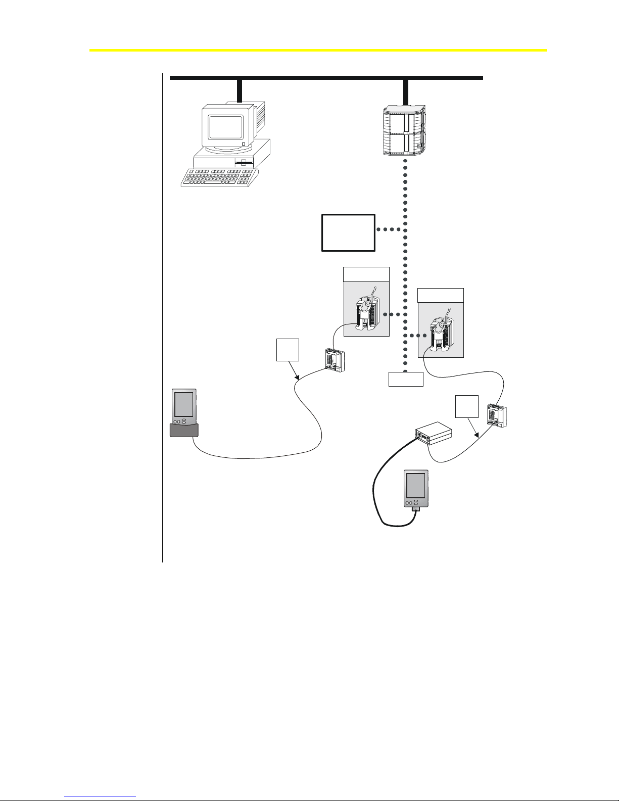
10
VMA1200
Operator Workst at i on
(with OWS, M-Pro,
and LNS S of tware)
LW
ON ORKS
Compatible
Devices
VMA1200
N1 LAN
Network Control Module (NCM)
LW
ON ORKS
Network
Bus
VMA1200
Zone
Bus
Room
Sensor
Palm Compatible
Handheld Device
CVTPRO
Converter
FTT-10
CablePRO
Converter
Zone
Bus
Room
Sensor
Palm Compatible
Handheld Device
MNET
Figure 1: VMA1200 Controllers in Metasys Network Diagram
Page 11

VMA1200 Series Overview and Engineering Guidelines
ON ORKS
L W Network
FTT-10
Interface
11
Window Open
Occupancy Sensor
Temp Occ Button
Space Temperature
Space Set point
Auxiliary Temperature
Auxiliary 0-10V
Low
Neuron
Digital
Inputs
x3
Analog
Inputs
x5
Hi
Differential
Pressure
(DP) Sensor
Application
Processor
COP8
IO Processor
Isolated
Phone
Jack
Zone
Bus
Analog
Output
x1
Triac
Outputs
x7
CW CCW
Actuator
Motor
Fblock2
TE-670 0, TMZ1600, or
Palm Compatible
Handheld Device
Heating Valve
Five 24 VAC Outputs for
Fan, Staged Heating, etc.
Figure 2: VMA1200 Functional Block Diagram
Page 12

12
VMA1200
Establish Zones
When designing VMA systems, establishing zones correctly is critical
to take maximum advantage of the VMA’s exceptional accuracy and
rapid response capabilities.
The designer strives for the most uniform indoor environmental
conditions possible. A single thermostatic device (room sensor)
controls each area. A zone could also be thought of as an area where
the load is considered the same for every square foot of floor space.
HVAC system zones fall into two major categories: exterior zones and
interior zones. Exterior zones are spaces directly affected by outdoor
weather conditions. Heat losses or outdoor air conditions do not
influence interior zones. Interior zones usually have cooling or
ventilation requirements only.
Further divisions of interior/exterior zones may be required to
accommodate different occupancy schedules and/or solar loads.
Variations in internal loading dictate the selection of separate zones.
For example, in a restaurant, the kitchen has vastly different heating
and cooling requirements from the seating area.
Room Sensor Placement
Consider room sensor placement for each zone, making sure to:
• Verify that the room sensor is the correct one for the application.
• Review architectural requirements such as furniture height and
location, aesthetics, and type of mounting. Wall plates are required
if mounting on a conduit handibox.
• Review room sensor location. The best room sensor location is on
an interior wall, about five feet above the floor, out of direct
sunlight, out of the direct path of supply air from the diffuser, away
from heat sources, such as equipment, machines, and perimeter
radiation, and away from doors and other draft sources. Mounting
height may be affected by local codes or the accessibility needs of
persons with disabilities.
• Do not locate a sensor near zone boundaries where primary
influence is from an adjacent zone.
Page 13

VMA1200 Series Overview and Engineering Guidelines
Pressure Independent VMA
The pressure independent VMA employs patented self-tuning,
cascaded proportional/integral control loops. The zone temperature
loop samples space temperature and resets the airflow setpoint
between the minimum and maximum flow settings. Since inlet duct
static pressure influences the amount of air passing through the
VAV box, the VMA airflow loop samples airflow via a flow pickup in
the box inlet. It modulates the damper to control the flow. Thus, the
VAV box flow is independent of duct static pressure.
The engineering basis for this method of control is that the temperature
of a space with a constant load is linearly proportional to the flow of
conditioned air into the space. The engineer must accurately determine
the required maximum and minimum flow for each space based on
heating, cooling, and ventilation loads.
VMA Ai r fl o w Ra t e
The VMA determines airflow rate by dynamic pressure measurement.
The VMA contains a Differential Pressure Transmitter (DPT) to sense
differential pressure in pressure independent VAV applications.
13
The DPT is connected to the VAV box airflow pickups. It measures
differential pressure and generates a proportional voltage signal. The
voltage signal from the DPT is read by the VMA and converted to
airflow in cubic feet per minute (cfm) or liters per second.
The DPT provides maintenance-free performance within the control
range of 1.25 to 18 m/s (250 to 3500 feet per minute [fpm]) when used
as recommended.
The minimum 1.25 m/s (250 fpm) velocity and the gain of the airflow
pickup produce an accurately measured pressure difference.
The VMA Auto Calibration function helps reduce the temperature
effect error by zeroing offset errors. As the ambient temperature
swings relative to the temperature at which the Auto Calibration
occurred, an offset error may occur (typically ±0.179 Pa/°C
[±0.0004 inch W.C./°F]). When calibration occurs, this error becomes
zero.
The error envelope becomes smaller with increased airflow pickup
gain and with smaller ambient temperature deviations at the
transmitter location.
Page 14

14
Power Source
VMA1200
You can use one 24 VAC power trunk to power multiple VMAs. In
this case, transformers of up to 100 VA are centrally located, and the
secondary run is without conduit and without concern about polarity.
Notes: The 24V power transformer must be UL/CSA listed as
NEC Class 2 Power Limited.
See NEC Article 725/Class 2 (30 VRMS maximum) and
(100 VA maximum).
The VMA1210 draws 7 VA including the internal damper actuator.
Therefore, 14 VMAs can be powered from one 100 VA transformer
without conduit. The number of VMA1220s is dependent on the
binary output loads and reheat actuators. The reheat actuators must be
added to the 7 VA of the controller, then divided into the 100 VA
transformer power. For example, the VMA1220 draws 7 VA without
loads. If there were only a single VA-8020 reheat valve per VMA, its
4 VA must be added to the VMA for a total of 11 VA. Then
nine VMA/VA8020s can be powered from one 100 VA transformer.
Table 3 shows the power rating for several cooling/heating coil valve
actuators. The valve power plus the VMA power must not exceed
100 VA. If a device is not listed in the following table, refer to the
product literature for that device.
Table 3: Actuator VA Power Rating
Actuator Type Power Rating
VA-8020
VA-8050
VA-7200
J Series Electric Zone Valve
VA-8022
VA-8052
VA-7202
VA-7450
VA-7452
VA-7050
VA-7310
VA-7312
VA-7010
VA-7150
VA-7152
Incremental 4 VA
Incremental 6 VA
Incremental 6.7 VA
On Off 7 VA
Voltage (0 to 10 VDC) 4 VA
Voltage (0 to 10 VDC) 6 VA
Voltage (0 to 10 VDC) 6.7 VA
Incremental 2.5 VA
Voltage (0 to 10 VDC) 2.5 VA
Thermal (DAO) 3 VA
Incremental 2 VA
Voltage (0 to 10 VDC) 2 VA
On/Off 7 VA
Incremental 2.7 VA
Voltage (0 to 10 VDC) 4.7 VA
Page 15

24 V A C
100 VA
VMA1200 Series Overview and Engineering Guidelines
When using a single transformer and running 24 VAC to multiple
VMAs, use a wire gauge large enough for the load. The voltage drop
on the 24 VAC cabling is much higher than for line voltage wiring for
the same power draw. For a 100 VA (equivalent to 100 watt) load at
120 VAC, only 0.8 ampere is required. However, at 24 VAC, over
four amperes are needed. Current draw determines the wire size.
Two connection methods are available. In the first method, individual
spade lugs accept a single 10 to 22 American Wire Gauge
(AWG)/4 mm2 to 0.8 mm wire and still fit on 6 mm (1/4 inch) tabs. In
the second method, optional screw terminals are assembled over the
spade lugs. The screw terminals accept up to a single 12 AWG
(4 mm2) wire or two 14 AWG (2.5 mm2) wires. When two wires are
crimped into one spade lug, a larger spade lug barrel is needed.
Alternately, a wire nut can connect two heavy wires to a short 152 mm
(6 inch) thinner wire.
< 88 ft of 14 AWG >
VMA
VMA
VMA
VMA
VMA
VMA
VMA
VMA
VMA
VMA
VMA
VMA
VMA
VMA
15
VMA
Example 1:
< 176 ft of 14 AWG >
VMA
VMA
VMA
VMA
VMA
VMA
VMA
Example 2:
Figure 3: Power Cable Lengths
A standard 14 AWG (2.5 mm2) wire (top example in Figure 3) is
All VMA s are at one end.
100 VA
24 V A C
< 176 ft of 14 AWG >
Transformer is centered.
VMA
VMA
VMA
VMA
VMA
VMA
VMA
VMA
Cablelength
limited to 27m (88 feet) with 14 cooling only VMAs when the VMAs
are all located at one end of the cable. If the transformer is centered
(bottom example in above figure) with seven VMAs on the left and
seven VMAs on the right, the distance in each direction can be
increased. This is because the current (and voltage drop) are halved in
each direction. In this example, both the left and the right legs can be
increased to 54m (176 feet) from the transformer, creating a 108m
(352 foot) total length.
Page 16

16
VMA1200
Table 4 and Table 5 indicate the relationship between wire length and
power at the end of wires.
Table 4: Maximum Wire Length for Given Power/Gauge (U.S. Measurements)
Wire Size
8 Gauge 10 Gauge 12 Gauge 14 Gauge 16 Gauge 18 Gauge
Power (VA) at
End of Wire
10
20
30
40
50
60
70
80
90
100
Wire Length (Feet)
3520 2200 1400 880 550 350
1760 1110 700 440 275 175
1173 740 467 293 183 117
880 555 350 220 138 88
704 444 280 176 110 70
587 370 233 147 92 58
503 317 200 126 79 50
440 278 175 110 69 44
391 247 156 98 61 39
352 222 140 88 55 35
Table 5: Maximum Wire Length for Given Power/
Wire Gauge (Metric Measurements)
Wire Size
2.5 mm
268
134
89
67
54
45
38
34
30
27
2
Power (VA) at
End of Wire
10
20
30
40
50
60
70
80
90
100
2
4 mm
Wire Length (Meters)
427
213
142
107
85
71
61
53
48
43
1.5 mm
168
84
56
42
34
28
24
21
19
17
2
Page 17

VMA1200 Series Overview and Engineering Guidelines
17
LONW
ORKS
Network Topology
The LONW
network topologies. Table 6 describes free topologies, and Figures 4
and 5 show supported topologies. For more information, see the
LONW
Table 6: Free Topologies
Category Free Topology
Architecture
Termination
Connection
ORKS
FTT-10A used by the VMA1200 supports free
ORKS
Network Layout Technical Bulletin (LIT-1162150).
Bus, star, ring, or mixed
Single termination for star, ring, or mixed
Double termination for bus
Connected by stub/multi-drop
Free Topology (Tree or Star)
Legend:
L W Compatible Device
ON ORKS
(Including NCM350/361)
Free Topology Terminator
Figure 4: Free Topology
Free_Top
Page 18

18
VMA1200
Daisy-chained TopologyBus
Stub-wired TopologyBus
Legend:
ON ORKS
L W Compatible Device
(Including NCM350/361)
Bus End- of - Line (EO L) Terminator
Bus_Top
Figure 5: Bus Topology
Table 7 contains a specification example for the FTT-10A Transceiver.
This is just one example of the many available wiring styles. For more
complete information, refer to Echelon Corporation
LONW
FTT-10A Transceiver User’s Guide.
ORKS
Table 7: FTT-10A Transceiver Specification Example
Transceiver
Topology
Bit Rate
Maximum Node to Node Distance
Maximum Total Wire Length
Maximum Nodes
Node Application Current
* Belden 85102, 8471 Cable
FTT-10/FTT-10A
Free
78 kbps
500m (1640 ft)*
500m (1640 ft)*
64
NA
Page 19

Inputs and Outputs
For specific input/output range, wire length, wire size issues, refer to
the VMA Wiring List in Appendix A: Reference Information at the back
of this document.
VMA1200 Series Overview and Engineering Guidelines
19
Note: All terminals are spade lug type except the LONW
ORKS
Network Bus terminals, which are removable screw terminals.
Optional two or three position kits can be ordered to convert
the spade lugs to removable screw terminals. See Table 12.
Binary Inputs
There are three dry contact binary inputs on the VMA1200. A manual
override button on the room sensor initiates a Temporary Occupancy
mode of operation. The TE-6700 room sensor includes an LED in
series with the button to show the occupancy mode. The switch can be
pushed for as little as 0.2 seconds to detect a change.
The binary inputs on the VMA are inactive when open. They are
active when a contact closure to binary input common (COM) is
applied.
Binary Outputs
The VMA has zero (VMA1210) or five (VMA1220) user accessible
binary outputs. The damper actuator is wired internal to the VMA.
Each load is connected between the BO terminal and BCOM common
terminal. When required to meet codes, the 24 VAC terminal of the
VMA/transformer can be earth grounded. In this situation, the binary
outputs switch the transformer’s low side to the relays and actuators.
Analog Outputs
There is one analog output on the VMA1220. The VMA1210 has no
analog outputs. The load is connected between the analog output and
analog output common (COM) terminals. The output is controlled to
generate a proportional voltage output of 0 to 10 VDC. The maximum
load for each output is 10 mA with a minimum load resistance of
1000 ohms.
Page 20

20
VMA1200
Analog Inputs
There are two external and one internal analog inputs on the
VMA1210 and four external and one internal analog inputs on the
VMA1220. They are preset for either temperature, setpoint, or voltage.
There are no jumpers to set. Shielding is not required, but if used, earth
ground the shield only at the VMA. You may use 24 AWG (0.6 mm)
twisted pair wire; however, this reduces the allowable wire length due
to the resistance. To minimize sensor error caused by field wiring, the
total resistance of the nickel or platinum resistive sensor wiring should
be less than 3 ohms. The NTC sensor accepts a larger wire resistance.
This wiring error effect is corrected through configuration properties
using a commissioning tool.
Do not share the temperature or setpoint common wire with voltage or
current transmitters on the Zone Bus. The maximum voltage drop on
the common wire must be less than 1 mV.
Zone Bus
The Zone Bus is a 2-wire local communications bus that allows a
Palm compatible handheld device with Johnson Controls VMA1200
Balancing Tool (VBT) software to commission and balance the VMA.
The Zone Bus connector also provides 15 VDC power to the
CablePRO or CVTPRO. The bus sustains no damage in the presence
of fault voltages of 15 VDC or 24 VAC.
Table 8: Zone Bus Specifications
Type
Speed
Recommended Cable Type
Maximum Bus Length
Voltages
Logic High Voltage
Logic Low Voltage
Data Tra nsmission
Isolation
Multi-drop serial communications bus
1200 baud (bits per second)
1.5 mm2 (18 AWG) with or without shield
(Belden 8760) or
0.6 mm (24 AWG) without shield (unshielded
telephone cable)
150 meters (500 feet) with 1.5 mm2 (18 AWG)
cable or
15 meters (50 feet) with 0.6 mm (24 AWG)
cable
4 VDC minimum (approximately)
1 VDC maximum (approximately)
1 Start Bit (low level)
8 Data Bits (least significant bit first)
1 Stop Bit (high level)
Isolated from 24 VAC, Binary Outputs (BO),
and L
ONWORKS
Network Bus
Page 21

CablePRO
CVTPRO
VMA1200 Series Overview and Engineering Guidelines
CablePRO (AS-CBLPRO) is an interface device used between a
21
Palm compatible handheld device and the VMA. It is used for box
balancing or commissioning via the Zone Bus communication port.
When used with a VMA, the CablePRO is strictly an electrical
interface between the serial RS-232 port of the Palm compatible
handheld device and the Zone Bus. CablePRO operates on 15 VDC,
drawn from a VMA through the Zone Bus phone jack. The data rate on
both the RS-232 and the Zone Bus is 1200 baud.
The connection to the RS-232 COM port of the Palm compatible
handheld device is by means of a DB9 or DB25 connector supplied
with the CablePRO.
Refer to the Auxiliary Gear Technical Bulletin (LIT-6363080) for
more information on the CablePRO.
Software Tools
CVTPRO (AS-CVTPROx00-0) is a Zone Bus/N2 interface device that
is used between a Palm compatible handheld device and the VMA. It
is used for box balancing or commissioning via the Zone Bus
communication port.
When used with a VMA, the CVTPRO is strictly an electrical interface
between the serial RS-232 port of the Palm compatible handheld
device and the Zone Bus. CablePRO operates on 15 VDC, drawn from
a VMA through the Zone Bus phone jack. The data rate on both the
RS-232 and the Zone Bus is 1200 baud.
Refer to the Auxiliary Gear Technical Bulletin (LIT-6363080) for
more information on the CVTPRO.
M-Tool software tools allow you to commission, configure, and
balance the VMA1200. Use M-Pro software to configure and
download applications. The VMA1200 Balancing Tool (VBT)
software allows you to balance and perform limited commissioning.
The Comm Pro commissioning tool performs commissioning
operations, such as reading and writing network variables and
configuration properties or downloading new firmware to the
controller.
In addition, a number of third-party network management tools (e.g.,
LonMaker software) allow you to read/write network variables and
configuration properties and bind network variables. See Table 13 in
Appendix A: Reference Information for additional software details.
Page 22

22
Related Documentation
VMA1200
Table 9 lists related VMA1200 documentation.
Table 9: Related Documentation
For Information on This Use This Document:
Sales and Marketing
information
Installing the VMA
Downloading and
Commissioning Details
Mounting and Wiring
Information
Troubleshooting VMA1200
Connecting to the
NCM/Workstation
Installing M-Pro and VBT
Configuring the VMA1200
Balancing the VMA1200
Working with LONW
Networks and Devices
ORKS
VMA1200 Series Controller Product Bulletin (LIT-1162300) in the
Metasys Network Sales Resource Manual (FAN 635) and the L
Systems Manual (FAN 1162)
VMA1200 Installation Bulletin, Part No. 24-9310-5 (Packed with product)
Downloading and Commissioning VMA1200 Series Controllers Technical
Bulletin (LIT-1162370)
Comm Pro User’s Guide (LIT-1162550)
Mounting and Wiring VMA1200 Series Controllers Technical Bulletin
(LIT-1162360)
Troubleshooting VMA1200 Series Controllers Technical Bulletin (LIT-1162380)
Metasys Network Technical Manual (FAN 636)
M-Tool Manual (FAN 693)
M-Pro User’s Guide (LIT-693300)
Variable Air Volume Modular Assembly (VMA) 1200 Series Controllers
Application Note (LIT-1162500)
Using the VMA1200 Balancing Tool (VBT) Software Technical Bulletin
(LIT-1162400)
ORKS
LONW
Compatible Devices Supported by NCM350 Technical Bulletin (LIT-1162100).
Network Layout Technical Bulletin (LIT-1162150) and LONW
ONWORKS
ORKS
Page 23

VMA1200 Series Overview and Engineering Guidelines
Procedure Overview
Table 10: Engineering the VMA Procedure Overview
To Do This Follow These Steps:
Determine VAV Box
Requirements
Establish the Room Schedule
Develop Bills of Material and
Place Orders
Configure the VMA
Select the VMA.
Establish sensor placement in zones.
Coordinate and authorize mounting.
Develop application configuration files.
Determine control strategy.
Select room sensors.
Create source power drawings.
Determine quantity needed of all components.
Make sure all items are included.
Coordinate parts ordering and delivery.
Reference appropriate room schedules.
Select control sequences using M-Pro.
Create configuration files.
Archive and document applications.
Download applications.
23
Page 24

24
Detailed Procedures
Determining VAV Box Requirements
VMA1200
To determine VAV box requirements:
1. Select the VMA based on control sequence, Input/Output (I/O),
side loops, and flow measurement accuracy requirements for
single duct boxes. Refer to the discussion of VMA Airflow Rate in
the Key Concepts section of this document.
2. Establish sensor placement in zones.
3. Contact box manufacturer’s representative to authorize mounting
or mount on site.
Notes: Damper shafts must protrude 44 mm (1-3/4 in.) or more
from the box. The VMA accommodates damper shafts
greater than 44 mm (1-3/4 in.) in length from the box exit.
Shaft bushings may interfere with flat mounting of the
VMA. If needed, use a spacer to keep the VMA parallel to
the mounting surface.
Things to consider:
• project install date
• plans and specifications
• wiring diagrams and specifications to box manufacturer
• who does what including: mounting, connecting, downloading,
testing, and shipping
• who provides which parts including: control enclosure and
transformer
4. Coordinate field or factory mounting.
Page 25

VMA1200 Series Overview and Engineering Guidelines
Establishing the Room Schedule
To establish the room schedule:
1. Develop application configuration files based on project
requirements.
For flow calculation constants, refer to the Variable Air Volume
Modular Assembly (VMA) 1200 Series Controllers Application
Note (LIT-1162500).
2. Determine control strategy.
Note: The VMA1200 is for single duct applications only. Use other
standard Johnson Controls VAV controllers for dual duct
and supply/exhaust applications.
3. Select appropriate room sensors based on project specifications.
Typically, each VMA requires a room sensor.
4. Create source power drawings. Determine such things as line
length, transformer count and layout, and power distribution.
25
5. Determine number of:
• VMAs
• other control devices
• room sensors
• valves
• valve actuators
• transformers
• phone cables
• accessories such as screw terminal kits
Page 26

26
VMA1200
Developing Bills of Material and Placing Orders
To write up the bill of material and place orders:
1. Make sure the following items are included as required:
• valves
• valve actuators
• room sensors (one per VMA)
• VMAs
• cables
• transformers
• box fan speed controllers - for information about the
Johnson Controls S66 Series Electronic Fan Speed Control,
refer to the S66 Series Electronic Fan Speed Control
Product/Technical Bulletin (LIT-121605) Part No. 24-8374-8
in the Installation Sheets Manual (FAN 121).
Notes: The differential pressure sensor and the damper actuator are
included as part of the VMA.
Room sensors cannot be hardwired/shared between VMAs;
however, sensors may be shared by connecting network
variables using a LONM
network management tool.
ARK
2. Coordinate parts ordering and delivery, including:
• placing orders through Johnson Controls Customer Service
• determining shipping destinations
• coordinating VMA manufacturing and delivery issues
• coordinating box manufacturer issues
• coordinating boxes with VMAs delivered to job
• determining status of software, documentation, and drawings
Note: The VMA can be shipped in individual packages or bulk
shipped (maximum ten VMAs per box).
Page 27

Configuring the VMA
Configure the VMA as specified in room schedules.
To configure the VMA:
1. Refer to the appropriate room schedule for room specifications.
2. Select control sequences using M-Pro software. Refer to
M-Pro User’s Guide (LIT-693300).
3. Create individual configuration files for each device or each set of
similar devices.
4. Archive and document the applications and VMA configuration
as needed. Downloading can be performed through the
LONW
Refer to the M-Pro User’s Guide (LIT-693300) for additional
configuration information.
VMA1200 Series Overview and Engineering Guidelines
ORKS
Network Bus.
27
Page 28

28
VMA1200
Appendix A: Reference
Information
Introduction
The following tables are to be used for wiring, parts, and specification
reference.
Page 29

VMA Wiring List
Table 11 provides a wiring list for the VMA1200. Figure 6 highlights
the electronic isolation of the VMA1200.
Note: All field terminals are power limited when powered by a
Table 11: VMA Wiring List
VMA1200 Series Overview and Engineering Guidelines
Class 2 transformer.
29
Point Description Range Input or
Load
Impedance
AI-1*
AI-2*
AI-3*
AI-4*
AI-5*
BI-1*
BI-2*
BI-3*
AO-1*
* Isolated from 24 VAC
Continued on next page . . .
Zone
Temperature
Zone
Setpoint
Humidity
Transmitter
or CO
2
Sensor
Perimeter
Temperature
or Supply Air
Temperature
Velocity
Pressure
(internal)
Temporary
Occupied
Comfort
(occupied)
Window, Off
(shutdown)
Proportional
Heat/
Humidity Fan
Speed
1K ohm
Nickel,
or Pt
2.25K ohm
NTC
1.6K ohm
2-wire Pot.
0-10 VDC 1.1M ohm 16.5 VDC 15 uA 0.6 mm to
1K ohm
Nickel,
or Pt
2.25K ohm
NTC
0 to 1.75 in.
W.C./0.5 to
2.0 VDC
0-5 VDC,
3V trigger
0-15 VDC,
2.5V trigger
0-15 VDC,
2.5V trigger
0-10 VDC 1K-10M ohm 10 VDC 10 mA
10K ohm 5 VDC 0.5 mA
10K ohm 5 VDC 0.5 mA 0.6 mm to
10K ohm 5 VDC 0.5 mA
10K ohm 5 VDC 0.5 mA
10K ohm 5 VDC 0.5 mA 0.6 mm to
100K ohm 5 VDC 20 uA NA Internal
440 ohm 5 VDC 10 mA
47K ohm 17 VDC 0.1 mA 0.6 mm to
47K ohm 17 VDC 0.1 mA 0.6 mm to
Maximum
Voltage
Maximum
Current
Wire Size in
2
mm
or mm
(AWG)
Cable
Length
in
Meters
(Feet)
1.5 mm2 (18) 150 (500)
0.6 mm (24) 30 (100)
1.5 mm
(24 to 18)
1.5 mm2 (18) 150 (500)
0.6 mm (24) 30 (100)
1.5 mm
(24 to 18)
1.5 mm2 (18) 150 (500)
0.6 mm (24) 30 (100)
1.5 mm
(24 to 18)
1.5 mm2 (18) 150 (500)
0.6 mm (24) 30 (100)
1.5 mm
(24 to 18)
1.5 mm
(24 to 18)
1.5 mm2 (18) 150 (500)
0.6 mm (24) 60 (200)
2
2
2
2
2
150 (500)
150 (500)
150 (500)
150 (500)
150 (500)
Page 30

30
VMA1200
Point
(Cont.)
Description Range Input or
Load
Impedance
BO-1,
2,3,4,5^
AM-1^
Network
Bus*^
Zone
Bus*
Room
Sensor
Cable*
+15
VDC*
24 VAC
Power
In^
Notes:
* Isolated from 24 VAC
^ Isolated from AI, BI, AO, Zone Bus, 15 VDC
+
See LONW
~
Length using 100 VA
Fan, Box/
Supplemental
24 VAC @
25-500 mA
48-1000 ohm 30 VAC 100 mA
Heat, Electric
Heat,
Lighting
Actuator
motor
24 VAC
4 VA
144 ohm 30 VAC 100 mA NA Internal
(internal)
Networking
Bus
±5V
transmit,
200 ohm line 5 VDC 100 mA 0.6 mm to
±0.2V
receive
Local Room
0 to 5V >3000 ohm 5 VDC 100 mA 1.5 mm2 (18) 150 (500)
Sensor Bus
AI-1, AI-2,
See above. 0.6 mm (24)
BI-1, Zone
Bus, and
+15 VDC
DC Output
14-18 VDC 1K-10M ohm 18 VDC 35 mA
Supply
AC Supply
22-30 VAC 12-48 ohm 30 VAC 0.3 ampere
Voltage
ORKS
Network Layout Technical Bulletin (LIT-1162150).
Maximum
Voltage
Maximum
Current
100 mA
500 mA
500 mA
for
VMA1210;
1.3 ampere
for
VMA1220
Wire Size in
2
mm
or mm
(AWG)
Cable
Length
in
Meters
(Feet)
2
1.5 mm
(18)
0.6 mm (24)
2
1.5 mm
(18)
0.6 mm (24)
1.5 mm
2
(24 to 18)
0.6 mm (24) 30 (100)
eight conductor
phone cable
1.5 mm2 (18) 150 (500)
0.6 mm (24) 60 (200)
6 mm2 (10) 67 (222)
6 mm2 (12) 42 (140)
2.5 mm2 (14) 27 (88)
1.5 mm2 (16) 17 (55)
2
1.5 mm
(18) 11 (35)
150 (500)
30 (100)
30 (100)
6 (20)
+
See
7.5 (25)
15 (50)
22.5 (75)
30 (100)
~
~
~
~
~
VMA1200
AI BI
Microprocessor
+15 VDC
Power Supply
24 VAC,
Motor,
BO
AO ZB
Figure 6: VMA Electronic Isolation
LW
ON ORKS
Communications
Circuit
Isolation
Page 31

VMA1200 Series Overview and Engineering Guidelines
VMA Wiring Interface Diagram
s
7
1
r
-
-
e
2
1
b
B
B
m
T
T
u
)
e
r
g
u
n
i
s
b
s
u
e
r
T
p
c
l
i
t
a
i
a
t
n
m
e
u
O
L
I
H
p
o
t
S
d
n
E
W
C
r
e
e
f
n
f
i
P
D
(
)
d
e
R
(
N
w
8
6
e
r
c
S
M
1
-
I
B
)
8
1
(
M
2
3
-
-
O
O
I
C
)
9
1
(
I
B
C
B
)
)
)
0
1
2
2
2
2
(
(
(
3
8
4
2
-
-
-
-
1
2
1
1
B
B
B
B
T
T
T
T
1
4
5
2
*
C
C
D
D
V
V
M
5
O
1
C
+
)
)
3
4
2
2
(
(
M
1
2
5
-
-
O
I
I
1
+
A
C
A
)
)
)
)
5
6
7
8
2
2
2
2
(
(
(
(
31
0
6
5
-
-
2
2
B
B
T
T
3
7
*
*
*
*
M
M
M
3
4
-
-
O
O
O
I
I
C
A
C
A
)
9
2
(
L
L
SHLD
C
)
)
)
)
0
1
2
3
3
3
3
3
(
(
(
(
O
B
N
A
N
O
e
)
0
p
y
0
l
o
r
7
n
-
u
O
E
E
(
T
*
*
*
0
0
7
6
E
T
M
+
O
B
C
Z
)
)
5
4
3
3
(
(
h
0
c
0
t
i
7
w
6
-
S
E
P
T
I
r
D
o
f
d
e
n
r
o
r
i
t
e
i
f
s
e
o
r
P
P
*
*
*
3
N
2
O
1
S
K
s
R
u
O
B
k
W
r
N
o
O
w
L
t
e
o
N
T
)
2
m
m
G
5
W
.
1
A
-
8
1
m
-
4
m
2
8
.
0
(
w
e
r
c
S
t
e
S
.
)
l
d
a
n
n
*
*
C
C
G
o
i
*
*
M
A
V
r
e
l
p
u
o
C
p
o
t
W
S
C
d
C
n
E
4
2
)
1
(
d
n
u
o
r
G
h
t
r
a
E
d
*
*
e
t
r
i
e
2
m
i
m
s
r
L
s
o
f
y
a
l
s
g
r
n
C
e
a
r
n
T
E
t
A
h
1
t
p
V
r
O
a
4
(
2
E
)
)
2
3
(
(
M
O
C
B
C
A
V
4
2
y
C
C
r
A
A
a
V
V
m
i
0
7
r
2
7
P
1
2
-
2
-
-
O
O
C
O
B
B
B
)
)
)
4
5
6
(
(
(
n
e
p
O
y
n
a
l
a
e
F
R
*
*
M
M
3
-
O
O
C
O
C
B
B
B
)
)
)
7
8
9
(
(
(
e
s
o
l
C
l
a
t
r
n
o
t
e
e
e
r
v
a
i
l
m
u
a
w
t
e
-
c
V
r
3
c
A
n
I
*
*
*
*
*
*
M
M
4
5
1
-
O
O
C
B
B
)
)
0
1
1
1
(
(
e
n
s
e
o
p
l
O
C
d
r
a
e
r
o
i
b
w
e
-
s
3
a
B
M
O
C
M
-
-
O
O
O
C
O
B
B
A
C
)
)
)
)
2
3
4
5
1
1
1
1
(
(
(
(
t
a
e
H
l
a
r
n
o
o
i
t
t
a
r
u
o
t
p
c
o
A
r
P
e
v
e
l
r
i
a
V
w
-
2
.
d
e
r
u
g
i
f
y
l
n
r
o
e
c
p
t
o
o
r
n
p
s
g
i
n
i
e
t
l
a
b
r
a
t
e
p
k
n
r
o
o
o
i
r
t
e
w
l
t
p
l
i
e
o
r
r
n
c
t
s
n
e
o
e
h
D
C
T
g
n
i
e
k
t
n
a
f
i
f
t
l
S
O
B
r
o
l
)
o
e
c
C
i
v
r
D
d
e
E
e
S
L
R
(
n
D
d
e
e
R
k
r
o
w
t
e
N
a
r
o
o
r
P
m
m
o
C
e
s
U
D
E
e
E
r
L
L
G
e
m
h
o
t
r
f
e
r
u
g
i
f
n
o
c
o
t
l
o
o
t
t
n
e
m
e
g
a
n
a
M
l
d
o
n
o
a
t
m
S
m
N
o
L
c
r
o
k
,
n
i
o
r
W
P
o
t
m
.
e
r
m
s
e
o
l
n
l
C
o
o
r
,
p
t
T
s
n
e
B
o
c
R
V
f
s
f
k
O
n
i
l
n
e
B
h
t
3
t
S
e
e
x
l
K
c
i
e
b
i
R
v
t
N
O
e
a
o
p
D
W
T
m
N
o
O
L
C
.
l
a
k
,
y
l
l
a
m
r
.
o
e
r
n
a
g
w
n
i
m
n
m
r
i
n
e
f
l
u
r
b
w
o
s
e
r
i
n
p
n
r
d
o
i
e
a
t
l
l
o
a
l
o
c
r
n
i
t
l
n
w
p
o
o
p
C
D
A
g
n
i
k
n
i
n
l
B
O
n
e
e
r
G
v
c
r
e
t
n
i
d
n
o
c
e
s
e
n
o
t
a
s
k
n
i
l
b
D
E
L
)
g
n
i
n
n
u
R
(
w
f
e
i
e
h
t
i
n
C
n
.
a
u
g
d
e
n
i
a
h
n
t
o
l
n
n
e
u
c
r
w
a
t
o
l
o
d
p
n
e
d
s
R
n
i
.
a
n
n
r
o
o
i
e
i
t
t
w
a
a
c
o
c
i
i
l
p
l
p
p
e
p
p
h
A
t
a
f
n
f
O
O
e
p
o
r
u
E
.
n
y
i
r
r
a
.
y
e
s
l
s
n
m
e
r
O
c
o
f
e
0
s
n
2
n
2
a
r
1
T
A
n
M
o
i
V
t
a
n
l
o
o
s
d
I
e
y
d
t
u
e
l
f
c
a
n
I
S
*
*
*
Figure 7: VMA Wiring Interface
Page 32

32
VMA1200
VMA Parts List
Table 12 lists hardware accessories. Table 13 lists software
requirements and options.
Table 12: Hardware Accessories (Order Separately)
Transformer
Screw Terminal Kit
Room Sensors
8-pin Room Sensor
Communication Cables
Electronic Fan Speed Controller
Handheld Interface
(for Balancing Tool software)
Converter (for Handheld
Interface)
Interface Accessories (for
Converter)
Table 13: Software
AS-XFR050 AS-XFR100 Y63 through Y66 Series
AP-TBK1002-0 Removable 2-position screw terminal kit (100 pcs)*
AP-TBK1003-0 Removable 3-position screw terminal kit (100 pcs)*
AP-TBK3COMM-0 Replacement L
screw terminal kit (10 pcs)
* These terminals fit over the existing I/O spade lugs.
TMZ-1600, TE-6700, TE-7000 (Europe only)
See the Room Sensor with LCD Display (TMZ1600) Technical Bulletin
(LIT-6363110) and the TE-6700 Series 2nd Generation Temperature
Elements Product Bulletin (LIT-216331) for information on room sensor
accessories.
S66AA-1C or S66DC-1C. See S66 Series Electronic Fan Speed
Control Product/Technical Bulletin (LIT-121605) for specifications.
Palm compatible handheld device (Version 2.0 or later operating
system). See Using the VMA1200 Balancing Tool (VBT) Software
Technical Bulletin (LIT-1162400) for more information on device
compatibility.
AS-CBLPRO-2 or AS-CVTPROx00-0
Required for AS-CBLPRO-2 only: Palm V Travel Kit cable (for the
Palm V) or Palm HotSync cable (for all other Palm models),
DB9M/DB9F Null Modem Adapter, DB9M/DB9M Gender Changer.
ONWORKS
Network Bus 3-position
Item Comments
Microsoft Windows 95,
Windows 98, or Windows NT
software
VMA1200 Balancing Tool (VBT)
M-Pro software
Comm Pro Commissioning Tool
LONW
(LNS) Network Management Tool
(Optional)
Network Services
ORKS
Platform
Used for Balancing. Part of M-Tool.
(Required for Configuration.) Can be used as a plug-in with third-party
network management tools or standalone. Part of M-Tool.
Can be used to commission a VMA1200 controller. Part of M-Tool.
Use a network management tool (e.g., LonMaker software) for
commissioning tasks.
Page 33

FCC Part 15 Label
This equipment has been tested and found to comply with the limits
for a Class A digital device pursuant to Part 15 of Federal
Communications Commission (FCC) rules. These limits are designed
to provide reasonable protection against harmful interference when
this equipment is operated in a commercial environment. This
equipment generates, uses, and can radiate radio frequency energy and,
if not installed and used in accordance with the instruction manual,
may cause harmful interference to radio communications. Operation of
this equipment in a residential area is likely to cause harmful
interference, in which case the user will be required to correct the
interference at his/her own expense.
This device complies with Part 15 of the FCC rules. Operation is
subject to the following two conditions:
1. This device may not cause harmful interference.
2. This device must accept any interference that may cause undesired
VMA1200 Series Overview and Engineering Guidelines
operation.
33
This Class A and B digital apparatus meets all requirements of the
Canadian Interference-Causing Equipment Regulations.
Page 34

34
VMA1200
VMA Specifications
Table 14: Basic VMA Specifications
Product Name
Product Code Number
Supply Voltage
Optional Fuse Current
Power Consumption
Ambient Operating
Conditions
Ambient Storage
Conditions
Terminations
Optional Terminations
Network Interfaces
LONW
Addressing
Communications
Protocols
Mounting
Housing
Dimensions (L x W x H)
Actuator Rating
Shipping Weight
Electrical Inputs
Velocity Pressure
Outputs
Standards Compliance
ORKS
Controller
Variable Air Volume Modular Assembly (VMA)
-0 (cooling only) or AP-VMA
AP-VMA
20 to 30 VAC at 50 or 60 Hz
0.3 ampere for VMA
7 VA maximum (relay and valve requirements not included)
0 to 50°C (32 to 122°F)
10 to 90% RH non-condensing, limited by a 30°C (86°F) maximum dewpoint
-40 to 70°C (-40 to 158°F)
6.3 mm (1/4 inch) spade lugs. (Communications has removable screw
terminals included.)
2 or 3 position screw terminals that plug into spade lugs (accessories)
L
Unique 48-bit ID
LON
Zone Bus between VMA controller and room sensor (8 pin phone jack or wire
to spade lugs)
One screw mounts the VMA to the VAV box.
One screw attaches damper shaft to the actuator 8 mm (5/16 inch) square
head set screw with 44 N.m (375 lb.in) of axial holding torque for up to 13 mm
(1/2 inch) round damper shafts.
Minimum damper shaft length is 44.5 mm (1 3/4 inch).
Plastic housing for controller, sensor and actuator with UL 94-5V Plenum
Flammability Rating
152.4 x 101.6 x 101.6 mm (6 x 4 x 4 inch)
4 N.m (35 lb.in) minimum
13.1 kg (29 lb) for a box of ten; 1.3 kg (2.8 lb) each
Analog Inputs: (Input configurations vary based on model type)
- Nickel (1K ohm Johnson Controls), or Platinum (1K ohm DIN 385) or
Binary Inputs: dry contacts
Velocity Pressure for 0 to 436 Pascal (0 to 1.75 inch W.C.)
No outputs on AP-VMA
Binary Outputs: 24 VAC triac switched; 25 to 500 mA loads
Damper Actuator: 90° rotation in 90 seconds
Analog Output: 0 to 10 VDC at 10 mA
CSA 22.2 No. 205
UL 916 UL 864 (UUKL) UL 94-5VB
FCC Part 15, Subpart B, Class A and B
CISPR 22, Residential Class B
CE Directive (89/336/EEC, EN50081/1, EN50082/2) Industrial and Residential
IEEE 472 ANSI C62.41 A/B (IEEE 587 Category A/B)
C-tick Australia/NZ, AS/NZS 4251.1
IEC 950 IEC 1000-4, -2, -3, -4, -5, -6
Refer to the Metasys Smoke Control Wiring Technical Bulletin (LIT-636331) in
the Metasys Network Technical Manual (FAN 636) for details on smoke
control compliance requiremen ts.
1210
1.3 ampere for a VMA
1210,
ONWORKS
NTC (2.25K ohm Fenwal) room sensors
- 1.6K ohm setpoint potentiometer (2-wire)
- Voltage Input for 0 to 10 VDC (humidity, dewpoint sensor, or sideloop)
Combination contact input w/LED driver for temporary occupancy on
TE-6700
Network Bus and Zone Bus
W
Network Bus between VMA controller and NCM (2-wire)
ORKS
-0, except internal damper actuator
1210
-0 (cooling with reheat/fan)
1220
fully loaded
1220
Page 35

VMA1200 Series Overview and Engineering Guidelines
All specifications are for the VMA controller pressure sensor and
actuator only, measured at the midpoint of each range within 90 days
of calibration at room temperature.
Table 15: Additional Detailed VMA Specifications
Power Input
Voltage Range 20 to 30 VAC; 50 or 60 Hz
Input Current 0.3 ampere without relays or valves
Transient Protection Control circuitry is transformer isolated from input power.
Common and Normal mode capacitor
LONW
Communications
Bus Type and Voltage FTT-10A, 2.5V differential signal
Bus Speed 78k Baud
Transient Protection Transformer isolated from 24 VAC, BOs, AI, BI, AO, ZBus, +15 VDC;
Zone Bus
Communications
Bus Type and Voltage Single-ended 5 VDC
Bus Speed 1200 Baud
Transient Protection Isolated from 24 VAC, BOs, and LONW
Microprocessor/Memory
Microprocessor
Memory 56K byte Flash
DC Supply Output
Voltage Range 14 to 18 VDC
Load Current 0 to 35 mA
Overload and Transient
Protection
Pressure Input (AI-5)
Range 0 to 435 Pascal (0 to 1.75 inch W.C.)
Proof Pressure 6895 Pascal (1 psi)
Burst Pressure 68940 Pascal (10 psi)
Resolution 0.0234 Pascal (0.000094 inch W.C.)
Non-repeatability and
Hysteresis
Non-linearity (Best Fit) ±2 Pascal (±0.008 inch W.C. maximum) for 0 to 249 Pa (0 to 1 inch W.C.)
Thermal Effect on Zero* ±0.179 Pascal per degree C (±0.0004 inch W.C. per degree F maximum)
Thermal Effect on Span ±0.179 Pascal per degree C (±0.0004 inch W.C. per degree F maximum)
Position Effect on Zero* ±0.623 Pascal (±0.0025 inch W.C. maximum)
Position Effect on Full Span ±0.623 Pascal (±0.0025 inch W.C. maximum)
Long Term Zero Drift* ±2.49 Pascal per year (±0.01 inch W.C. per year maximum)
Long Term Span Drift ±2.49 Pascal per year (±0.01 inch W.C. per year maximum)
Sample Time One second
Continued on next page . . .
Network Bus
ORKS
Spark gaps, series blocking capacitors, clamping diodes, transformer
communications circuit;
ORKS
PTC+Transorb; Common mode capacitors
Neuron 3150 processor operating at 10 MHz
Current Foldback; Isolated from 24 VAC, BOs, and LONW
communications circuit; Common mode capacitors
±0.187 Pascal (±0.00075 inch W.C. maximum)
±3 Pascal (±0.012 inch W.C. maximum) above 249 Pa (>1 inch W.C.)
ORKS
35
Page 36

36
VMA1200
Additional Specifications (Cont.)
Temperature Inputs
(AP-VMA
(AI-1, AI-2, AI-4)
Range
NTC: 0 to 40°C (32 to 104°F)
Platinum: 0 to 40°C (32 to 104°F)
Nickel: 0 to 40°C (32 to 104°F)
Setpoint: 18 to 30°C (65 to 85°F)
Resolution (13 bit)
NTC: 0.0028°C (0.0050°F)
Platinum: 0.0589°C (0.1060°F)
Nickel: 0.0430°C (0.0774°F)
Setpoint: 0.0015°C (0. 0027°F)
Non-repeatability and
Hysteresis (estimate)
NTC: ±0.009°C (±0.016°F) maximum
Platinum: ±0.189°C (±0.340°F)
Nickel: ±0.138°C (±0.248°F)
Setpoint: ±0.005°C (±0.009°F) maximum
Measurement Accuracy
NTC: ±0.03°C (±0.05°F) maximum
Platinum: ±0.68°C (±1.23°F) maximum
Nickel: ±0.50°C (±0.90°F) maximum
Setpoint: ±0.15°C (±0.27°F) maximum
Thermal Tolerance
±0.020% per °C (±0.036% per °F) maximum
Long Term Drift ±0.07% per year maximum
Sample Time One second
Transient Protection
Isolated from 24 VAC, BOs, and LON
Normal mode RC; Common mode capacitors
Temporary Occupied
100 mS
Response Time (AI-1)
Voltage Input (AI-3)
(AP-VMA
Range 0 to 10.0 VDC (0 to 2000 PPM CO2)
Resolution (13 bit) 0.750 mV (0.15 PPM CO2)
Non-repeatability and
±0.012 V maximum (±2.4 PPM CO2)
Hysteresis (estimate)
Measurement Accuracy ±75 mV maximum (±15 PPM CO2)
Thermal Tolerance
±0.028% per °C (±0.050% per °F) maximum
Long Term Drift ±0.7% per year maximum
Sample Time One second
Transient Protection Isolated from 24 VAC, BOs, and LONW
Normal mode RC; Common mode capacitors
Binary Inputs
Voltage Range and
Trigger Level
BI-1: 0 to 5 VDC with 3.1 VDC threshold
BI-2 and BI-3: 0 to 5 VDC with 2.5 VDC threshold
Sample Time 50 mS pulse width (10 Hz maximum)
Transient Protection Isolated from 24 VAC, BOs, and LONW
Normal mode RC; Common mode capacitors
Continued on next page . . .
only for AI-4)
1220
only)
1220
W
communications circuit;
ORKS
communications circuit;
ORKS
communications circuit
ORKS
Page 37

VMA1200 Series Overview and Engineering Guidelines
Additional Specifications (Cont.)
Analog Output (AO-1)
Voltage Range 0 to 10 VDC
Load Current 0 to 10 mA
Voltage Resolution
(8 bit)
Linearity and Hysteresis ±0.04 VDC maximum
Voltage Accuracy ±3% full scale
Thermal Tolerance
Long Term Drift ±0.7% per year maximum
Time Constant one second (seven seconds for steady state)
Transient Protection Isolated from 24 VAC, BOs, and LONW
Binary Outputs
(BO-1 through BO-5)
Voltage Range 20 to 30 VAC
Load Current 25 to 500 mA
Time Constant 50 mS
Transient Protection Isolated from AI, BI, AO, ZBus, +15 VDC, and LONW
Motor Actuator Output
Rated Running Torque
Unpowered Holding
Torque
Stall Torque
Stroke 93±3 degrees maximum
Angular Velocity 1 degree per second nominal
Full Stroke Life 100,000 cycles minimum
Reposition Stroke Life 2,500,000 cycles minimum
Reposition Accuracy ±1 degree maximum
Acoustic Noise 30 dBA at one meter maximum
* Use the Auto Calibration function to correct. Specifications are deemed accurate but are subject to change.
(AP-VMA1220 only)
0.04 VDC
±0.005% per °C (±0.009% per °F) maximum
communications circuit;
ORKS
Common mode capacitors
(AP-VMA1220 only)
communications
ORKS
circuit; Common mode capacitors; Normal mode capacitors and resistors
4 N⋅m (35 lb⋅in) minimum
5.1 N⋅m (45 lb⋅in) minimum
9.1 N⋅m (80 lb⋅in) maximum
37
Page 38

38
VMA1200
Fabricating Your Own Interconnection Cable
You must construct any fabricated interconnection cable, so the same
color wire on both ends of the cable align with Pin 1 in the plug. This
provides a consistent field assembly of the cable. Figure 8 illustrates
the interconnection cable.
8
7
6
5
4
3
2
1
VMA1200
Controller
Phone Plug
BI-1
AI-2
AI-1
AI-1 COM
+15 VDC
ZB COM
AI COM
ZB+
1234567
TE-670 0 R oom Sens or
Phone Plug
Figure 8: Interconnection Cable
8
Phone Connector s
(Clip Side Out)
Cblfab_1
Note: This is not typical of preassembled phone cable purchased in
retail stores. A telephone system cable is wired opposite of
the Zone Sensor requirements.
Page 39

Sensor Interface
AI-1 (Zo ne Temperature)
+15/Zone Bus COM (Not BCOM)
VMA1200 Series Overview and Engineering Guidelines
39
Figures 9, 10, and 11 show interfaces between room sensors and the
VMA1200. For more information on the TE-6700 room sensor
(including Dual Inline Package (DIP) switch settings), see the TE-6700
Series 2nd Generation Temperature Elements Installation Bulletin
(LIT-216332).
8-pin P hone Jack
on TE-6700
BI-1
AI-2 (Setpoint)
AI COM
+15 Volts DC
AI-COM
Zone Bus/N 3+
Screw
Terminals
1
8
4
2
3
1
2
4
5
5
6
6
7
3
7
8
LED*
Sensor
Manual
Override
1K ohm
1.6K ohm
Setpoint Potentiometer
6-pin P hone Jack
on TE-6700
1
2
3
4
5
6
+15 Volts DC
COM
Zone Bus
TE6X
Figure 9: TE-6700 Phone Jack Interface to VMA1200
Page 40

40
VMA1200
VMA
(18) BI-1*
(19) COM
(20) BI-2
(21) COM
(22) BI-3
(23) COM
(24) +1 5 VD C
(25) +1 5 VD C
(26) AI-1
(27) COM
(28) AI-2
(29) COM
(30) AI-3
(31) COM
(32) AI-4
(33) COM
(34) ZB+
(35) ZB-
AI
COMAICOM
AI1
1
8
ZB+ COM 15 VDC
BI-1
AI2
4
5
O N
Preferred DIP Switch
Position for TE-6700
1 2 3
screw term
Figure 10: TE-6700 Interface to VMA1200 (Terminal Block)
Page 41

VMA
VMA1200 Series Overview and Engineering Guidelines
TE-7000 (Europe Only)
Terminal Blocks (TBs)
TB1 TB2
1234 5678
(18) BI-1
(19) COM
(20) BI-2
(21) COM
(22) BI-3
(23) COM
(24) +1 5 VD C
(25) +1 5 VD C
(26) AI-1
(27) COM
(28) AI-2
(29) COM
(30) AI-3
(31) COM
(32) AI-4
(33) COM
(34) ZB+
(35) ZB-
41
TE7000
Figure 11: TE-7000 (Europe Only) Interface to
VMA1200 (Terminal Blocks)
Note: The IU-9100 converter is not compatible with the VMA1200
Zone Bus.
Page 42

42
VMA1200
Appendix B: Application Example
This example is provided as a basic overview of wiring locations you
might expect to see. It does not define all applications available or all of
the possible questions and answers. For more information on VMA1200
applications, see the Variable Air Volume Modular Assembly (VMA)
1200 Series Controllers Application Note (LIT-1162500).
Single Duct Application Example
Table 16: Single Duct Application Example Questions
M-Pro Questions Configuration Selections
VAV Box Type
Fan Type (R1)
Baseboard Heat Type
Box Heat Type (HTG)
Pressure Independent
Series/On-Off
None
2-stages
Note: The Orig inal Equ ipment Man ufactur er (OE M) bo x manufa c turer
typically supp lies t he fan re lay s and e lectr ic hea t rel ay s.
R2
Plenum
Supply
DPT1
R3
H
T
G
Discharge
DA1
R1
C
1
Figure 12: Single Duct Application Example
TE
1
Sample1
Mechanical Flow Diagram
Page 43

VMA1200 Series Overview and Engineering Guidelines
Table 17: Single Duct Application Example Bill of Materials
Component Description Part Number
C1, DPT1, DA1
TE1
R1
R2, R3
* Box OEM manufacturers typically furnish fan relays and electric heat relays.
Power
Transformer
120 VAC 24 V A C
Fan Relay
Stage 1 Relay
Stage 2 Relay
R1
R2
R3
VMA AP-VMA1220-0
Temperature Sensor and Setpoint TE-6700 Series
Fan *
Reheat Relays *
(1) 24 VAC
(2) 24 VAC
(3) Earth
Ground
24 VAC
24 VAC
24 VAC
(4) BO-1
(5) BCOM
(6) BO-2
(7) BCOM
(8) BO3
(9) BCOM
(10) BO-4
(11) BCOM
(12) BO-5
(13) BCOM
(14) AO-1
(15) COM
LON B
LON A
SHLD
HI
(Red)
(18) BI-1
(19) COM
(20) BI-2
(21) COM
(22) BI-3
(23) COM
(24) +1 5 VD C
(25) +1 5 VD C
(26) AI-1
(27) COM
(28) AI-2
(29) COM
(30) AI-3
(31) COM
(32) AI-4
(33) COM
(34) ZB+
(35) ZB COM
1
8
43
LO
4
5
Figure 13: Single Duct Application Example
To Next
LW
ON ORKS
Compatible
Device
Pressure Independent Configuration
O N
Preferred DIP Switch
Position for TE-6700
1 2 3
TE-6700
To Next
LW
ON ORKS
Compatible
Device
Ex1
Page 44

44
VMA1200
Notes
Controls Group FAN 1162
507 E. Michigan Street L
P.O. Box 423 Release 1.0
Milwaukee, WI 53201 Printed in U.S.A.
www.johnsoncontrols.com
ONWORKS
Systems Manual
 Loading...