

Page 1
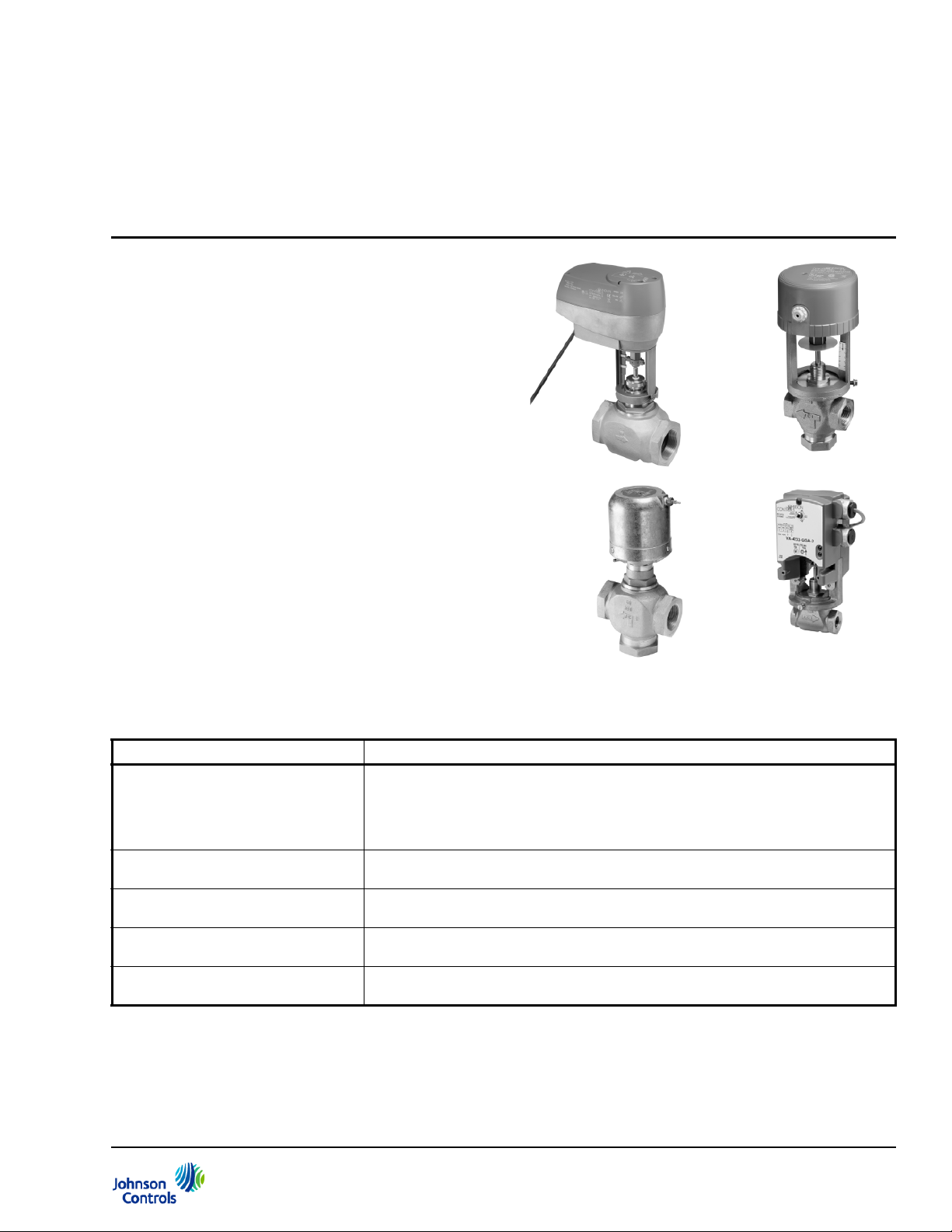
Figure 1: VG7000 Series Bronze Control Valves
VG7000 Series Bronze Control Valves
Product Bulletin
VG7000 Series
Refer to the QuickLIT website for the most up-to-date version of this document.
VG7000 Series Bronze Control Valves are designed
primarily to regulate the flow of water and steam in
response to the demand of a controller in Heating,
Ventilating, and Air Conditioning (HVAC) systems.
These valves are available in Normally Open (N.O.),
Normally Closed (N.C.), and three-way mixing
configurations. Both electric and pneumatic actuators
are available for factory or field mounting.
Code No. LIT-977140
Issued November 15, 2013
Supersedes March 29, 2013
Table 1: Features and Benefits
Features Benefits
Complete Family of 1/2 through
2 in. Bronze Valves, Brass and
Stainless Steel Trim, with Several
Styles of Electric and Pneumatic
Actuators
Flexible Features and Options
Ordering Matrix
Standard Johns on Controls®
Ring Pack Packings
Testing for Tight Shutoff of Every
Valve
Standard Bonnet and Stem Design Allows easy field retrofit, easy field mounting, and interchangeability of actuators with
Offers a broad selection to choose from, including electric spring return actuators, a
true 1-1/4 in. valve body, a 3/4 in. valve with small oval top actuator, and Stainless
Steel (SS) trim capable of 100 psig (690 kPa) saturated steam.
Suits your specific application via thousands of easy-to-select, factory-assembled
combinations.
Provides industry-leading reliability and operating life.
Provides energy conservation and ensures occupant comfort.
the use of standardized mounting kits.
VG7000 Series Bronze Control Valves Product Bulletin 1
Page 2

Ordering Data
Table 2: Ordering Data — VG7000 Series Bronze Control Valves
V G
1 2 7
3 2
4 4 = Two-Way, Normally Closed/Push-Down-to-Open
4
5 5 = Union Globe/Union Angle (1/2 through 1-1/2 in. Body
1
6 2 = Brass Linear (Three-Way Only)
L
7 E = 1/2 in., 1.8 Cv (1.6 Kv)
T
8 S = Slotted Stem and Small Bonnet (Factory-Mounted
+
9 (Leave Fields 9 through 15 blank for valve without
Valve Globa l
Product Family
Body Type
End Connections
Trim and Flow
Characteristics
Size and Cv (Kv)
Stem Type
Actuator
Mounting
7 = Cast Bronze
2 = Two-Way, Normally Open/Push-Down-to-Close
5 = Two-Way Angle, Normally Open/Push-Down-to-Close
8 = Three-Way Mixing
4 = Threaded National Pipe Thread (NPT)
Sizes, PDTC Only, Brass Trim Valves Only))
7 = Union Sweat, 3/8 in. Tubing (1/2 in. Body Size Only,
Brass Trim Valves Only))
8 = Union Sweat, Standard Tubing (Brass Trim Valves
Only)
9 = Union Sweat, 3/4 in. Tubing (1/2 in. Body Size Only,
Brass Trim Valves Only))
1 = Brass Equal Percentage (All Two-Way and 1/2 in.
Three-Way)
3 = Stainless Steel Equal Percentage (Two-Way Only)
4 = Stainless Steel Linear (Three-Way Only)
C = 1/2 in., 0.73 Cv (0.63 Kv)
G = 1/2 in., 4.6 Cv (4.0 Kv)
L = 3/4 in., 7.3 Cv (6.3 Kv)
N = 1 in., 11.6 Cv (10.0 Kv)
P = 1-1/4 in., 18.5 Cv (16.0 Kv)
R = 1-1/2 in., 28.9 Cv (25.0 Kv)
S = 2 in., 46.2 Cv (40.0 Kv)
T = Standard Threaded Stem (All Except V-3801, MP84,
VA-8x2x)
V-3801, VA-8x2x Only; Only Brass Trim Valves)
M = Large Threaded Stem (Factory-Mounted MP84 Only,
Only Stainless Steel Trim Valves)
+ = Factory-Mounted Actuator
(See Table 3 and Table 4.)
factory-mounted actuator. Valve without factory-mounted
actuator is available with standard threaded stem only.)
1
1 23456789101112131415 = Field
V G7 241LT + Example: Cast bronze valve, two-way, normally open/push-down-to-close,
Valve + Actuator
threaded (NPT) end connections, brass trim, equal percentage,
3/4 in., 7.3 Cv, standard threaded stem.
1. See Table 3 when adding a factory-mounted pneumatic actuator to a valve body. See Table 4 when adding a
factory-mounted electric actuator to a valve body. For valid valve and actuator combinations, see Table 16 and Ta ble 17.
VG7000 Series Bronze Control Valves Product Bulletin2
Page 3
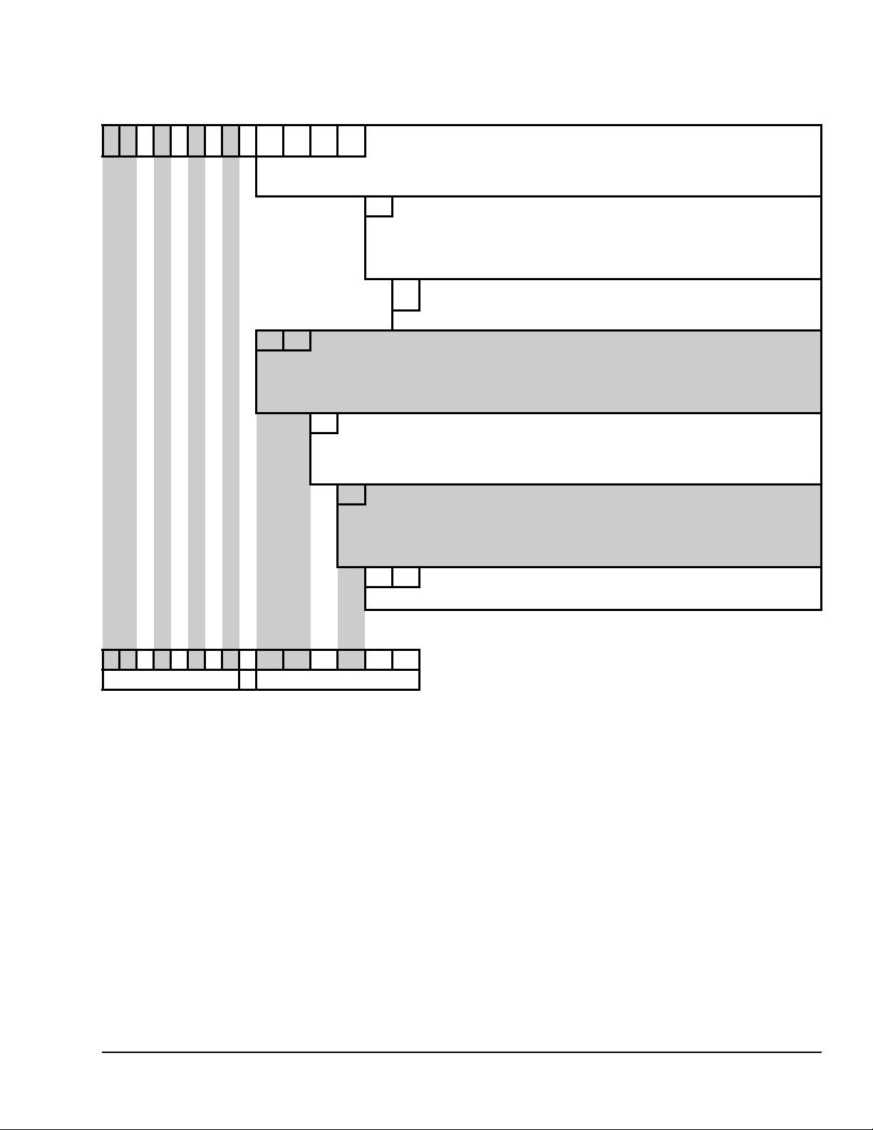
Table 3: Ordering Data — Adding a Factory-Mounted Pneumatic Actuator
V G7 243LT + 3 0 0 8 V-3000/V-3801
1 2345678 9 10 11 12 13 3008 = V-3000-8012 Exposed
B Spring Range
14 D = 4 to 8 psig (Suggested for Three-Way Valves with
8 2 MP8000 Series
10 11 84 = MP84, 50 sq in. Spring-Return-Up (SS Trim Only)
1Stroke
12 2 = 1/2 in. (1 or 1-1/4 in. Valves with MP82 Actuator Only)
C Spring Range
13 D = 4 to 8 psig (Suggested for Three-Way Valves with
0 1 Accessories
14 15 01 = V-9502 Positioner
Pneumatic
Actuator
(V-3000/V-3801)
P Accessories
(V-3000/V-3801)
15 Blank = None
Pneumatic
Actuator
(MP8000
Series)
(MP8000
Series)
(MP8000
Series)
2
2
3801 = V-3801-8001 Small Oval Top (Slotted Stem Only,
Brass Trim Valves Only, Must be Factory Assembled)
3003 = V-3000-8003 Enclosed
B = 3 to 6 psig (Suggested for N.O. Valves with Positioner)
Positioner)
E = 9 to 13 psig (Suggested for N.C. Valves with
Positioner)
P = V-9502 Positioner (Not Available with V-3801-8001 or
V-3000-8003)
82 = MP82, 25 sq in. Spring-Return-Up (SS or Brass Trim)
(Only spring-return-up models of MP8000 Series
Pneumatic Actuators are available factory-mounted to
VG7000 Series Bronze Control Valves.)
1 = 5/16 in. (1/2 or 3/4 in. Valves with MP82 Actuator Only)
3 = 3/4 in. (1-1/2 or 2 in. Valves with MP82 or MP84
Actuator)
C = 3 to 7 psig (Suggested for N.O. Valves with Positioner)
Positioner)
E = 9 to 13 psig (Suggested for N.C. Valves with
Positioner)
00 = None
1
1 2345678910 11 12 13 14 15 = Field
V G7 243LT+8 21C 0 1 Example: Cast bronze valve, two-way, normally open, threaded (NPT) end
Valve + Actuator
connections, stainless steel trim, equal percentage, 3/4 in., 7.3 Cv, standard
threaded stem, MP82 Series Pneumatic Actuator, 5/16 in. stroke, 3 to 7 psig
(21 to 48 kPa) spring range, with factory-mounted V-9502 Positioner.
1. See Table 2 when ordering a valve body only. See Table 4 when adding a factory-mounted electric actuator to a valve body.
For valid valve and actuator combinations, see Table 16 and Table 17.
2. Refer to the actuator product bulletin or product/technical bulletin.
VG7000 Series Bronze Control Valves Product Bulletin 3
Page 4
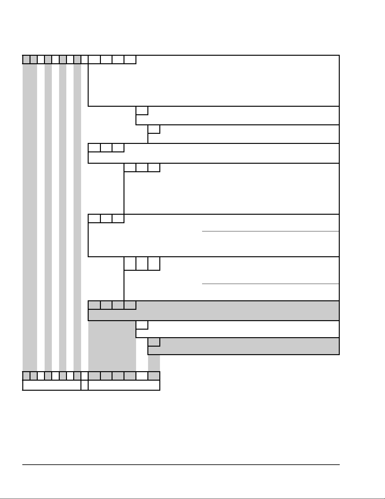
Table 4: Ordering Data — Adding a Factory-Mounted Electric Actuator
V G7 241LT + 7 1 5 0 VA-7150/
1 2345678 9 10 11 12 13 7152 = VA-7152-1001 Proportional, 0-10 VDC
VA-7200
Electric
Actuator
2, 3
7150 = VA-7150-1001 On/Off (Floating)
7153 = VA-7153-1001 On/Off (Floating), Feedback
1
7200 = VA-7200-1001 On/Off (Floating)
7202 = VA-7202-1001 Proportional, 0-10 VDC
7203 = VA-7203-1001 On/Off (Floating), Feedback
G Voltage
14
(VA-7150/
VA-7200)
Accessories
(VA-7150/
15
VA-7200)
4 2 3 VA-4233
10 11 12 423 = VA-4233-xGx-2, 24 VAC/VDC
A G A Features
13 14 15 AGC = Floating, 2 Auxiliary Switches
Electric
Actuator
(VA-4233)
2
4
G = 24 VAC
Blank = None
Spring Return Up
AGA = Floating
BGA = On/Off
BGC = On/Off, 2 Auxiliary Switches
GGA = Prop., 0-10 VDC, Feedback
GGC = Prop., 0-10 VDC, Feedback, 2 Auxiliary Switches
9 2 N VA7810
10 11 12 71C = VA7810-xGx-2, 24 VAC/VDC
VA7820/
VA7830
Electric
Actuator
5
2,6
Non-Spring Return
Spring Return
72C = VA7820-HGx-2, Spring-Return Stem Up 24 VAC
74C = VA7830-HGx-2, Spring-Return Stem Down 24 VAC
G G A Features
(VA78x0)
7
13 14 15 AGC = On/Off (Floating), 2 Auxiliary Switches
AGA = On/Off (Floating)
(Available only with VA7810 Actuator)
(Available only with VA7810)
HGA = Proportional, 0-10 VDC, Feedback
HGC = Proportional, 0-10 VDC, Feedback, 2
8 0 2 0 VA-8x2x
10 11 12 13 8122 = VA-8122-1, Proportional
G Voltage
14
Electric
Actuator
(VA-8x2x)
Accessories
(VA-8x2x)
15
2,3, 8
8020 = VA-8020-1, On/Off (Floating)
G = 24 VAC
Blank = None
1 2345678910 11 12 13 14 15 = Field
V G7 241LT+8 0 2 0G Example: Cast bronze valve, two-way, push-down-to-close, threaded (NPT)
Valve + Actuator
end connections, brass trim, equal percentage, 3/4 in., 7.3 Cv, standard
threaded stem, VA-8020-1 On/Off (Floating) Electric Actuator, 24 VAC supply.
1. See Table 2 when ordering a valve body only. See Table 3 when adding a factory-mounted pneumatic actuator to a valve body.
For valid valve and actuator combinations, see Table 16 and Table 17.
2. Refer to the actuator product bulletin or product/technical bulletin.
3. Available only for PDTC Two-Way and Three-Way body styles.
4. Available only for NPT (threaded) and Union Sweat End Connections body style.
5. VA7830 actuator is available only on Three-Way Mixing body style.
6. Available only for NPT (threaded) body style.
7. VA7820 and VA7830 Proportional Control Actuators have selectable switches for field conversion to On/Off or Floating Control.
8. Available only for 1/2 and 3/4 in. valves.
VG7000 Series Bronze Control Valves Product Bulletin4
Page 5

Application Overview
IMPORTANT: The VG7000 Series Bronze Control
Valves are intended to control saturated steam, hot
water, and chilled water flow under normal
equipment operating conditions. Where failure or
malfunction of the VG7000 Series Valve could lead
to personal injury or property damage to the
controlled equipment or other property, additional
precautions must be designed into the control
system. Incorporate and maintain other devices,
such as supervisory or alarm systems or safety or
limit controls, intended to warn of or protect against
failure or malfunction of the VG7000 Series Valve.
VG7000 Series Bronze Control Valves feature brass
and stainless steel trim, and are available in two-way
configurations with Push-Down-to-Close (PDTC)
(normally open if pneumatic or spring return) or
Push-Down-to-Open (PDTO) (normally closed if
pneumatic or spring return) with threaded (NPT), union
sweat, union globe, and union angle end connections.
The valve can be ordered with a variety of pneumatic
actuators: V-3000-8012 (exposed, with or without a
factory-mounted positioner), V-3000-8003 (enclosed),
V-38 01-8001 (oval top), and higher force MP8000
Series Actuators (with or without a factory-mounted
pneumatic positioner).
VG7000 Series Valves can also be ordered with any of
the following series electric actuators: VA-4233,
VA-7150, VA-7200, VA-8x2x, VA7810, VA7820, or
VA7830. All electric actuators are fully compatible with
Johnson Controls® controllers, reducing installation
costs. V alves without actu ators can be ordered with the
standard bonnet and threaded stem design, allowing
easy interchangeability of actuators with the use of
standardized mounting kits. See Table 2 through
Table 4 for ordering data and additional details. For
valid valve and actuator combinations, see Table 16
and Table 17.
The modulating valve plug of VG7000 Series Valves
provides an equal percentage flow characteristic for
two-way valves, and equal percentage or linear for
three-way valves. Tight shutoff is ensured using a
molded elastomeric disk in valves with brass trim, and
a precisely machined metal-to-metal seat for valves
with stainless steel trim. An arrow is cast on one side of
the valve body indicating the directio n of flow for proper
piping.
Pneumatic Actuator Selection
See Table 7, Table 9, Table 11, and Table 16.
Do not confuse the V-3000-8012, V-3000-8003, and
V-3801-8001 Pneumatic Actuators with the V-3000-1,
V-3000- 2, and V-3802-1 Pneumatic Actuators. Refer to
the V-3000-80 11 (Exposed) and V-3000-8003
(Enclosed) Pneumatic Valve Actuators Product/
Technical Bulletin (LIT-977252) for specifics regarding
interchangeability. The V-3801-8001 is not a direct
replacement for the V-3802-1 because V-3802-1 is not
compatible with VG7000 Series Valves.
V-3801-8001 Pneumatic Actuator
The V-3801-8001 is a low force, oval top actuator
designed specifically for 1/2 and 3/4 in. valves where
mounting space is restricted. The V-3801-8001 has
sufficient force to handle most seating pressures, and
the molded diaphragm design provides a constant
effective area (4 sq in.) throughout the valve stem
stroke. Due to the simplicity of the design, it is more
economical to replace the actuator than repair it. The
actuator assembly can be removed or repositioned by
loosening a single set screw without disturbing the rest
of the valve assembly.
Because the V-3801-8001 uses a unique slotted valve
stem for factory assembly (see the Stem Type section
in Table 2), the spring kits available are for field
mounting to standard threaded stem valves. See
Table 7 for mounting kit code numbers.
V-3000-8012 Pneumatic Actuator
The V-3000-8012 is a versatile, medium-force
pneumatic actuator that can be used in most HVAC
applications, including sequential control of valves. See
Table 9 and Table 11 for actuator sizing and selection.
The permanently captured, molded rolling diaphragm
of the V-3000-8012 provides a constant effective area
(8 sq in.) throughout the valve stem stroke. The
actuator assembly can be removed or repositioned by
loosening a single set screw without disturbing the rest
of the valve assembly.
The V-9502 Pneumatic Positioner is also available for
factory or field mounting to the V-3000-8012.
V-3000-8003 Pneumatic Actuator
The V-3000 -8003, operationally similar to the
V-3000-8012, is designed for enclosed installation in a
location where the actuator might be subjected to
tampering. The V -3000-8003 has a r eplaceable molded
diaphragm design.
VG7000 Series Bronze Control Valves Product Bulletin 5
Page 6

MP8000 Series Pneumatic Actuators
The higher force MP82 (25 sq in. effective diaphragm
area) and MP84 (50 sq in. effective diaphragm area)
Pneumatic Actuators are used where higher maximum
closeoff pressures are required, such as 1-1/2 and 2 in.
brass trim valves and 1/2 through 2 in. stainless steel
trim valves.
These actuators are equipped with a molded synthetic
rubber diaphragm contained in a sturdy, carbon-steel
housing that protects it against dirt and damage. The
actuator can be easily removed to perform inline
servicing to all parts of the valve. The MP8000
Actuators are available factory mounted or are easily
field mounted to VG7000 Series Valves. See Table 7
for the appropriate mounting kit.
The MP8000 Actuators are designed to allow for
reversing the action of the actuators in the field. If
desired, the action of the MP8000 on Normally Open
(N.O.) valves can be reversed from spring-return-up to
spring-return-down or vice versa. To field reverse the
actuator, refer to the MP8000 Pneumatic Valve
Actuators Technical Bulletin (LIT-977258).
The V-9502 Pneumatic Positio ner is also available for
factory or field mounting to MP8000 Series Pneumatic
Valve Actuators.
T-3000 Valve Top Thermostat Actuators
The T-3111 and T-3311 Series Valve Top Thermostat
Actuators are available for field mounting to all VG7000
Series Valves (N.O., N.C., and three-way). The valve
top thermostats are a combination of a pneumatic
thermostat and a pneumatic valve actuator. The T-311 1
and T-3311 are available in both direct an d reverse
acting models with various features and options. Refer
to the T-3111 Integral Thermostat a nd Piston Top V alve
Actuator Single Temperature, Single Pressure Product/
Technical Bulletin (LIT-7171137) and the T-3311
Integral Thermostat and Piston Top Valve Actuator
Dual Temperature, Dual Pressure Product/Technical
Bulletin (LIT-7171152) for specifications and ordering
information.
Note: A mounting kit is required to field mount T-3111
or T-3311 Valve Top Thermostats to a valve. See
Table 7 for the appropriate mounting kit code number.
Electric Actuator Selection
Factory-mounted electric actuators are available on
two-way PDTC and three-way mixing valve
configurations only. Actuators can be easily field
reversed if required. The actuators can be field
mounted on PDTO valves if desired. All proportional
electric actuator assemblies are factory calibrated for
nominal 0 to 10 VDC operation, to drive down with an
increase in signal. The VA-4233 and VA78x0 are
available on all valve styles: PDTO, PDTC, and threeway.
VA-4233 Series Electric Actuators
The VA-4233 Series Electric Actuators use a stepper
motor to accurately position the valve. In the event of a
power failure, a spring in the actuator automatically
returns the valve to the full stem-up position. These
direct-mount, spring return electric actuators provide a
minimum 61 lb force output for floating, on/off, or
proportional control, and can be factory mounted to
1/2 through 1-1/4 in. valve bodies with NPT (threaded)
and union sweat end connections.
Integral auxiliary switches are available for indicating
end stop position or to perform switching functions. On
proportional models, position feedback is also available
through a proportional DC voltage signal. All models
feature a hand crank for manual positioning of the
valve, independent of a power supply.
VA-7150 Series Electric Actuators
The VA-7150 Series Actuators use a reversible
synchronous motor and magnetic clutch to accurately
position the valve. This non-spring return actuator has
a 90 lb force output. The magnetic clutch maintains a
constant load at the end of travel, ensuring tight valve
shutoff and automatically compensating for seat wear.
This actuator is available in three models: floating
three-wire (VA-7150), floating with 0 to 2000 ohm
feedback (VA-7153), or 0 to 10 VDC proportional
control (VA-7152).
VA-7200 Series Electric Actuators
The VA-7200 Series Actuators use a reversible
synchronous motor and a magnetic clutch to accurately
position the valve. This non-spring return actuator has
a 180 lb force output. The magnetic clutch maintains a
constant load at the end of travel, which ensures tight
shutoff and automatically compensates for seat wear.
This actuator is available in three models: floating
three-wire (VA-7200), floating with 0 to 2000 ohm
feedback (VA-7203), or 0 to 10 VDC (0 to 20 mA)
proportional control (VA-7202).
VG7000 Series Bronze Control Valves Product Bulletin6
Page 7

VA-8x2x Series Electric Actuators
The VA-8x2x Series Actuators are synchronous
motor-driven, force sensor limited, non-spring return
actuators that feature a 22 lb seating force in a
compact design. The VA-8020 accepts floating control
from a three-wire, 24 VAC control signal. The VA-8122
typically accepts proportional control from a 0 to
10 VDC control signal; however, it can be field adjusted
to accept signals up to 20 VDC. In addition, the
V A-81 22 features a n input signal re versing fe ature that
allows it to be used in both heating and cooling
applications.
Note: The VA-8x2x is only available factory mounted
on 1/2 and 3/4 in. valves. Because the VA-8x2x
requires a unique slotted valve stem for factory
assembly, it is necessary to select the S option in the
Stem Type section of Table 2.
VA7810 Series Electric Actuators
The VA7810 Series is a line of motor driven, direct
mount, non-spring return actuators that operate on
24 VAC and are available for use with on/off (floating)
or proportional controllers. The actuator is available
factory mounted to 1/2 through 2 in. valve body styles
with NPT (threaded) end connections. The actuator is
available separately for field mounting to union sweat,
union globe, and union angle VG7000 Series valves.
The actuator delivers a minimum stem force of 180 lb.
Integral auxiliary switches are available for indicating
end-stop position or to perform switching functions. For
proportional models a 0 (2) to 10 VDC signal feedback
is available.
VA7820/VA7830 Series Electric Actuators
The VA7820/VA7830 Series is a line of motor driven,
direct mount, spring return actuators that operate on
24 VAC. The actuators ship alread y set for 0 to 10 VDC
Proportional control. With a simple change of DIP
switch settings, the actuator can be reconfigured in the
field for On/Off (Floating) Control. Position feedback is
available via switches or a 0 (2) to 10 VDC signal. The
actuator delivers a minimum stem force of 180 lb. If the
power fails, the automatic spring returns the valve stem
up for the VA7820 actuator or the valve stem down for
the V A7830 actu ator. A manual override allows manual
positioning of the valve when power is not available.
The actuator is available factory mounted to 1/2
through 2 in. valves body styles with NPT (threaded)
end connections. The actuator is available separately
for field mounting to union sweat, union globe, and
union angle VG7000 Series valves.
VG7000 Series Bronze Control Valves Product Bulletin 7
Page 8
Shipping Weights
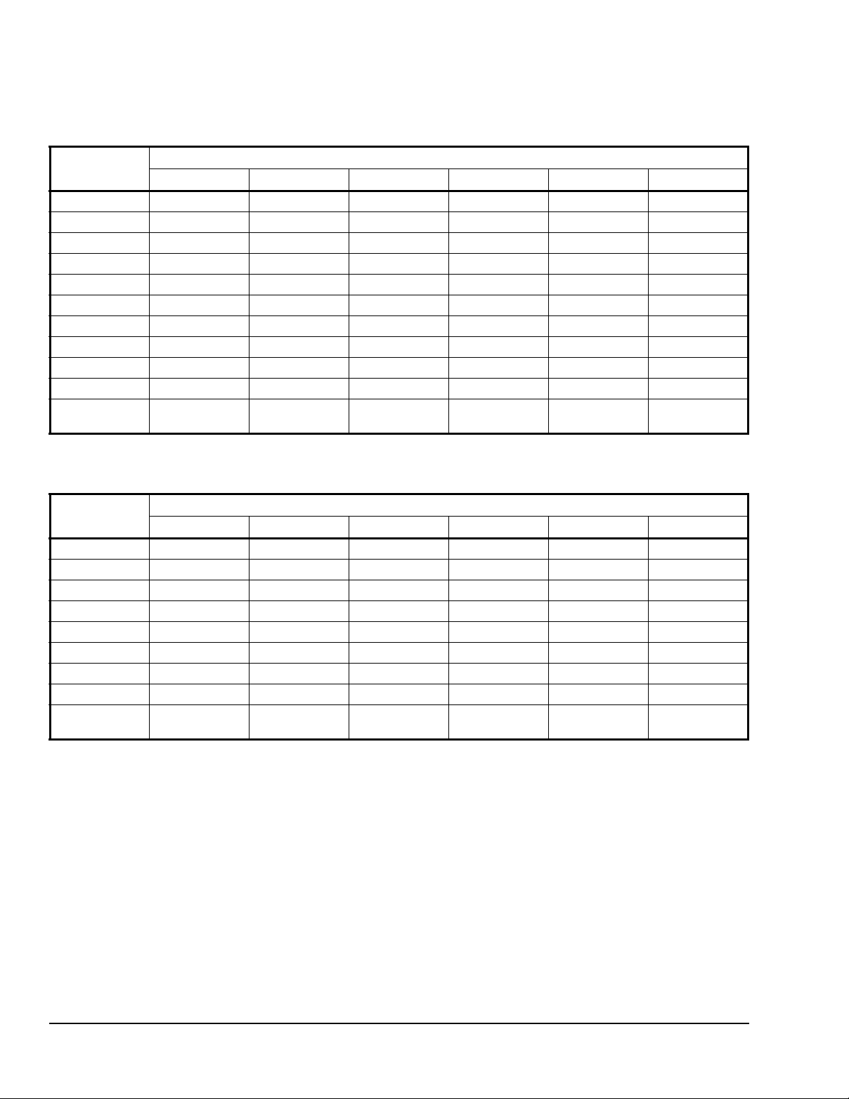
Table 5: Shipping Weights for Brass Trim Valves
Actuator Valve Weight, lb
1/2 3/4 1 1-1/4 1-1/2 2
V-3801-8001 2.5 3.1 --- --- --- --V-3000-8012 3.4 4.5 6.5 6.5 12.1 17.2
V-3000-8003 3.2 4.3 6.3 6.2 11.9 17.0
MP82 --- --- 14.0 16.0 19.0 24.0
MP84 --- --- --- --- --- --VA-4233 5.3 6.4 8.4 8.3 --- --VA-7150 3.9 5.0 7.0 6.9 12.6 17.7
VA-7200 --- --- 7.5 7.4 13.1 18.2
VA-8x2x 4.6 5.9 --- --- --- --VA7810 --- --- 6.2 6.2 11.8 16.9
VA7820/
VA7830
1. Weights are approximate and based on the heaviest valve. Add 2 lb (0.9 kg) for pneumatic assemblies with a positioner.
--- --- 7.9 7.9 13.5 18.6
1
Table 6: Shipping Weights for Stainless Steel Trim Valves
1
Actuator Valve Weight, lb
1/2 3/4 1 1-1/4 1-1/2 2
V-3000-8012 3.7 4.5 6.9 8.9 --- ---
V-3000-8003 3.5 4.2 6.7 8.7 --- ---
MP82 11.0 12.0 14.0 16.0 19.0 24.0
MP84 --- --- --- --- 32.0 37.0
VA-4233 5.3 5.6 8.0 10.0 --- ---
VA-7150 3.9 4.2 6.6 8.6 12.6 17.7
VA-7200 4.7 5.5 7.9 9.9 13.1 18.2
VA7810 3.1 4.2 6.6 8.6 11.8 16.9
VA7820/
VA7830
1. Weights are approximate and based on the heaviest valve. Add 2 lb (0.9 kg) for pneumatic assemblies with a positioner.
4.8 5.9 8.3 10.3 13.5 18.6
VG7000 Series Bronze Control Valves Product Bulletin8
Page 9
Field Mounting
A standard bonnet/stem design allows for easy field
mounting of actuators. See Table 2 to order valves
without actuators; Table 7, and Table 8 to order the
appropriate mounting kits; and Table 16 and Table 17
to identify compatible actuators. Refer to the
appropriate actuator product bulle tin fo r spe cif ic
actuator code number information.
Table 7: Field Mounting Kits for Pneumatic Actuators
Actuator Style
T-3x11
V-3000-8012
Valve Size, in. (DN)
1/2 or 3/4 (DN15 or DN20)
5/16 in. (8 mm) Stroke
V-3000-8003
T-3x11
V-3000-8012
1 or 1-1/4 (DN25 or DN32)
1/2 in. (13 mm) Stroke
V-3000-8003
T-3x11
V-3000-8012
1-1/2 or 2 (DN40 or DN50)
3/4 in. (19 mm) Stroke
V-3000-8003
V-3801-8001 1/2 or 3/4 (DN15 or DN20)
5/16 in. (8 mm) Stroke
V-3801-8001 1/2 or 3/4 (DN15 or DN20)
5/16 in. (8 mm) Stroke
MP82/MP83 1/2 or 3/4 (DN15 or DN20) with Stainless
Steel Trim
MP82/MP83 1 through 2 (DN25 through DN50) with 1/4 in.
Stem and Stainless Steel or Brass Trim
MP84/MP85 1-1/2 through 2 (DN40 through DN50) with
3/8 in. Stem and Stainless Steel Trim
2
1
Spring Range psig (kPa) Mounting Kit
Code Number
3 to 6 (21 to 41) VG7000-1001
4 to 8 (28 to 55) VG7000-1002
9 to 13 (62 to 90) VG7000-1003
3 to 6 (21 to 41) VG7000-1004
4 to 8 (28 to 55) VG7000-1005
9 to 13 (62 to 90) VG7000-1006
3 to 6 (21 to 41) VG7000-1007
4 to 8 (28 to 55) VG7000-1008
9 to 13 (62 to 90) VG7000-1009
3 to 6 (21 to 41) VG7000-1010
4 to 8 (28 to 55) VG7000-1011
9 to 13 (62 to 90) VG7000-1012
Kit with Three Springs:
3 to 6, 4 to 8, and 9 to 13 (Includes
hardware to adapt one valve only.)
Not Applicable MP8000-6701
Not Applicable MP8000-6702
Not Applicable MP8000-6703
VG7000-1015
3
3
3
3
3
3
3
3
3
3
3
3
3
4
4
5
1. Use all mounting kits with valves with standard threaded stem design only.
2. DN is the European designation for body size in metric units (mm).
3. The mounting kits include: upper spring seat, spring, stem extension, stem locking screw (or set screw), and a
bonnet adaptor for the V-3801-8001. Use this only on valves with threaded stems.
4. The mounting kits include: stem nut (1), stem extender nuts (2), stem extender (1), and yoke nut (1).
5. The mounting kit includes: stem nuts (2) and yoke nut (1).
Table 8: Field Mounting Kits for Electric Actuators
1
Actuator Style Valve Size, in. (DN) Mounting Kit Code Number
VA-4233 1/2 through 1-1/4 (DN15 through DN32) None Required
VA-715x 1/2 through 2 (DN15 through DN50) None Required
VA-720x 1 through 2 (DN25 through DN50) None Required
VA-8x2x 1/2 and 3/4 in. (DN15 and DN??) VA-8020-100 (Refit only)
VA78x0 1/2 through 2 (DN15 through DN50) None Required
1. Use all mounting kits with valves with standard threaded stem design only.
VG7000 Series Bronze Control Valves Product Bulletin 9
Page 10
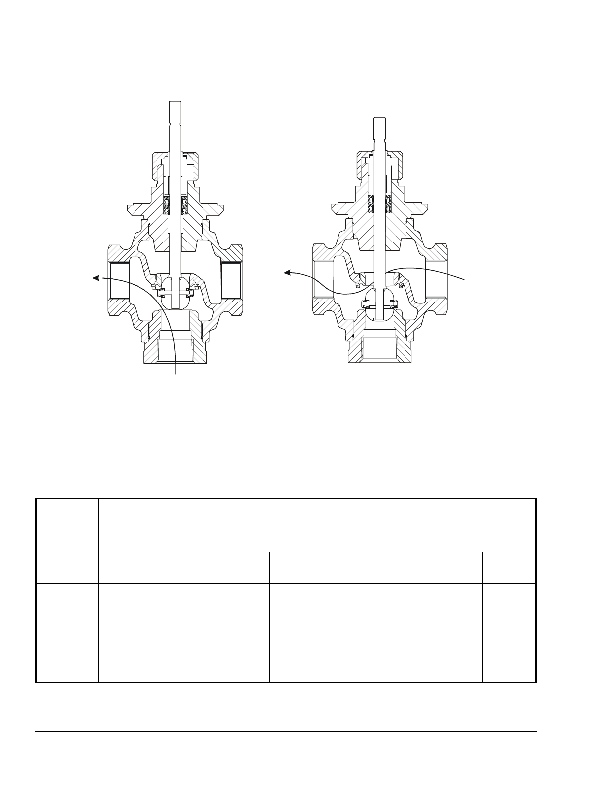
Stem Up Position
the lower port (N.O.) is open
to the Common port (C).
C
C
Stem Down Position
the inline port (N.C.) is open
to the Common port (C).
N.O.
(PDTC)
N.O.
(PDTC)
N.C.
N.C.
(PDTO)
F
I
G
:
V
G
7
F
G
0
2
P
Figure 2: Three-Way Mixing Valves Fluid Flow Direction and Port Designation
(PDTO)
With the stem in the up position,
With the stem in the down position,
Table 9: Brass Trim – Maximum Closeoff Pressures, psig (kPa) for Pneumatically Actuated Valves (Part 1
of 2)
Actuator
Style
V-3801-8001
(248°F
[120°C])
Valve Size,
in. (DN)
Brass Trim
1/2
(DN15)
3/4
(DN20)
Maximum
Cv (Kv)
Factor
0.73
(0.63)
1.8
(1.6)
4.6
(4.0)
7.3
(6.3)
Two-Way Normally Open or
Three-Way N.O. Port
(with 20 psig Supply)
Spring Range (psig
2
3 to 6
(21 to 41)
186
(1,282)
186
(1,282)
105
(723)
67
(462)
4 to 8
(28 to 55)
157
(1,082)
157
(1,082)
89
(613)
56
(386)
(62 to 90)
1
)
9 to 13
84
(579)
84
(579)
48
(331)
30
(207)
Two-Way Normally Closed or
Three-Way N.C. Port
(with 0 psig Supply)
Spring Range (psig)
2
3 to 6
(21 to 41)
37
(255)
37
(255)
18
(124)
11
(76)
4 to 8
(28 to 55)
57
(393)
57
(393)
28
(193)
16
(110)
1
9 to 13
(62 to 90)
158
(1,089)
158
(1,089)
76
(524)
45
(310)
VG7000 Series Bronze Control Valves Product Bulletin10
Page 11

Table 9: Brass Trim – Maximum Closeoff Pressures, psig (kPa) for Pneumatically Actuated Valves (Part 2
of 2)
Actuator
Style
V-3000-8012
(284°F
[140°C])
and
V-3000-8003
(248°F
[120°C])
MP82
(284°F
[140°C])
Valve Size,
in. (DN)
Brass Trim
1/2
(DN15)
3/4
(DN20)
1
(DN25)
1-1/4
(DN32)
1-1/2
(DN40)
2
(DN50)
1
(DN25)
1-1/4
(DN32)
1-1/2
(DN40)
2
(DN50)
Maximum
Cv (Kv)
Factor
0.73
(0.63)
1.8
(1.6)
4.6
(4.0)
7.3
(6.3)
11.6
(10)
18.5
(16)
28.9
(25)
46.2
(40)
11.6
(10)
18.5
(16)
28.9
(25)
46.2
(40)
Two-Way Normally Open or
Three-Way N.O. Port
(with 20 psig Supply)
Spring Range (psig
2
3 to 6
(21 to 41)
365
(2,515)
365
(2,515)
225
(1,550)
144
(992)
90
(620)
55
(379)
35
(241)
22
(152)
279
(1,924)
170
(1,172)
109
(752)
70
(483)
4 to 8
(28 to 55)
339
(2,336)
339
(2,336)
192
(1,323)
122
(841)
76
(524)
47
(324)
30
(207)
19
(131)
257
(1,772)
157
(1,082)
100
(689)
64
(441)
(62 to 90)
1
)
9 to 13
191
(1,316)
191
(1,316)
108
(744)
69
(475)
42
(289)
26
(179)
16
(110)
11
(76)
148
(1,020)
90
(621)
58
(400)
37
(255)
Two-Way Normally Closed or
Three-Way N.C. Port
(with 0 psig Supply)
Spring Range (psig)
2
3 to 6
(21 to 41)
100
(689)
100
(689)
49
(338)
29
(200)
17
(117)
10
(69)
6
(41)
4
(28)
70
(483)
40
(276)
25
(172)
16
(110)
(28 to 55)
4 to 8
142
(978)
142
(978)
68
(469)
41
(282)
25
(172)
14
(96)
9
(62)
6
(41)
96
(662)
55
(379)
34
(234)
21
(145)
1
9 to 13
(62 to 90)
348
(2,398)
348
(2,398)
168
(1,158)
100
(689)
(448)
(255)
(158)
(96)
223
(1,536)
128
(883)
(545)
(345)
65
37
23
14
79
50
1. The recommended spring ranges for use with a V-9502 Positioner are: 3 to 6 psig (21 to 41 kPa) and 3 to 7 psig
(21 to 48 kPa) for N.O. valves, 9 to 13 psig (62 to 90 kPa) for N.C. valves, and 4 to 8 psig (28 to 55 kPa) for three-way valves.
2. 3 to 7 psig (21 to 48 kPa) for MP82 Actuators.
Table 10: Brass Trim – Maximum Fluid Temperature for Pneumatically Actuated Valves
Actuator Style Water Saturated Steam
V-3801-8001 248°F (120°C) 15 psig (103 kPa)
V-3000-8012 284°F (140°C) 38 psig (262 kPa)
V-3000-8003 248°F (120°C) 15 psig (103 kPa)
MP82 284°F (140°C) 38 psig (262 kPa)
VG7000 Series Bronze Control Valves Product Bulletin 11
Page 12

Table 11: Stainless Steel Trim – Maximum Closeoff Pressure, psig (kPa) for Pneumatically Actuated Valves
Actuator
Style
V-3000-8012
and
V-3000-8003
(338°F
[170°C])
MP82
(338°F
[170°C])
MP84
(338°F
[170°C])
3
3
3
Valve
Size, in.
(DN)
SS Trim
1/2
(DN15)
3/4
(DN20)
1
(DN25)
1-1/4
(DN32)
1/2
(DN15)
3/4
(DN20)
1
(DN25)
1-1/4
(DN32)
1-1/2
(DN40)
2
(DN50)
1-1/2
(DN40)
2
(DN50)
Maximum
Cv (Kv)
Factor
0.73
(0.63)
1.8
(1.6)
4.6
(4.0)
7.3
(6.3)
11.6
(10)
18.5
(16)
0.73
(0.63)
1.8
(1.6)
4.6
(4.0)
7.3
(6.3)
11.6
(10)
18.5
(16)
28.9
(25)
46.2
(40)
28.9
(25)
46.2
(40)
Two-Way Normally Open or
Three-Way N.O. Port
(with 20 psig Supply)
Spring Range (psig
2
3 to 6
(21 to 41)
299
(2,060)
299
(2,060)
169
(1,164)
108
(744)
67
(462)
41
(282)
308
(2,124)
308
(2,124)
308
(2,124)
308
(2,124)
209
(1,440)
128
(882)
82
(565)
52
(358)
165
(1,137)
106
(730)
4 to 8
(28 to 55)
255
(1,757)
255
(1,757)
144
(992)
92
(634)
57
(393)
35
(241)
308
(2,124)
308
(2,124)
308
(2,124)
304
(2,095)
193
(1,330)
118
(813)
75
(517)
48
(331)
152
(1,047)
97
(668)
(62 to 90)
1
)
9 to 13
143
(985)
143
(985)
81
(558)
52
(358)
32
(220)
19
(131)
308
(2,124)
308
(2,124)
275
(1,895)
175
(1,206)
111
(765)
68
(469)
43
(296)
28
(193)
88
(606)
56
(386)
Two-Way Normally Closed or
Three-Way N.C. Port
(with 0 psig Supply)
Spring Range (psig)
2
3 to 6
(21 to 41)
75
(517)
75
(517)
36
(248)
22
(152)
13
(90)
7
(48)
280
(1,929)
280
(1,929)
135
(930)
81
(558)
53
(365)
30
(207)
19
(131)
12
(83)
39
(269)
24
(154)
(28 to 55)
4 to 8
106
(730)
106
(730)
51
(351)
31
(214)
19
(131)
11
(76)
308
(2,124)
308
(2,124)
183
(1,261)
109
(751)
72
(496)
41
(282)
25
(172)
16
(110)
53
(365)
33
(227)
1
9 to 13
(62 to 90)
(1,798)
(1,798)
(868)
(517)
(338)
(193)
(2,124)
(2,124)
(2,124)
(136)
(1,158)
(661)
(407)
(255)
(834)
(524)
261
261
126
75
49
28
308
308
308
252
168
96
59
37
121
76
1. The recommended ranges for use with a V-9502 Positioner are: 3 to 6 psig (21 to 41 kPa) and 3 to 7 psig (21 to 48 kPa) for
N.O. valves, 9 to 13 psig (62 to 90 kPa) for N.C. valves, and 4 to 8 psig (28 to 55 kPa) for three-way valves.
2. 3 to 7 psig (21 to 48 kPa) for MP82 and MP84 Actuators.
3. The maximum closeoff pressure listed is limited to the maximum allowable American Nati onal Standards Institute (ANSI)
valve body rating corresponding to the maximum temperature rating (308 psig [2,122 kPa] at 338°F [170°C]) of the valve.
VG7000 Series Bronze Control Valves Product Bulletin12
Page 13

Table 12: Brass Trim – Maximum Closeoff Pressures, psig (kPa) for PDTC Two-Way and PDTC Port for
1
3/4
(DN20)
1
(DN25)
2
1-1/4
(DN32)
1-1/2
(DN40)
2
(DN50)
Valve
Size,
Three-Way Electrically Actuated Valves
284°F (140°C) Maximum Fluid Temperature
1/2
(DN15)
in. (DN)
Maximum
Cv (Kv)
0.73
(0.63)
1.8
(1.6)
4.6
(4.0)
7.3
(6.3)
11.6
(10.0)
18.5
(16.0)
28.9
(25.0)
46.2
(40.0)
Factor
VA-715x 345
(2,377)
VA-720x --- --- --- --- 179
VA-4233 345
(2,377)
VA78x0 --- --- --- --- 182
VA-8x2x 112
(772)
1. The maximum closeoff pressure listed is limited to the maximum allowable ANSI valve body rating corresponding to the
maximum temperature rating (345 psig [2,377 kPa] at 281°F [138°C]) of the valve, except for VA-8x2x Actuators that are
limited to 195°F (91°C) maximum temperature and 381 psig (2,625 kPa) pressure rating.
The maximum closeoff pressures listed are for actuators coupled to the appropriate mounting kits listed in Table 7 and
Table 8. See Table 16 and Table 17 for valid factory-mounted combinations, and Table 7 and Table 8 for available field
mounting kits.
2. The maximum fluid temperature is 284°F (140°C) water to 38 psig (262 kPa) saturated steam except for the following:
VA-4233 Actuators are limited to 35 to 250°F (2 to 121°C) water to 15 psig (103 kPa) saturated steam.
VA-8x2x Actuators are limited to 195°F (91°C) water, and are not rated for steam applications.
345
(2,377)
345
(2,377)
80
(551)
216
(1,488)
208
(1,433)
45
(310)
138
(951)
132
(909)
29
(200)
86
(593)
(1,233)
63
(434)
(1,254)
--- --- --- ---
52
(358)
109
(751)
38
(262)
111
(765)
34
(234)
70
(482)
--- ---
71
(489)
21
(145)
45
(310)
46
(317)
Table 13: Brass Trim – Maximum Closeoff Pressures, psig (kPa) for PDTO Two-Way and PDTO Port for
Three-Way Electrically Actuated Valves
1,2
Not Available Factory Coupled for PDTO Two-Way — Field Mounting Only
3
1-1/4
(DN32)
1-1/2
(DN40)
2
(DN50)
Valve
Size,
284°F (140°C) Maximum Fluid Temperature
1/2
(DN15)
3/4
(DN20)
(DN25)
1
in. (DN)
Maximum
Cv (Kv)
0.73
(0.63)
1.8
(1.6)
4.6
(4.0)
7.3
(6.3)
11.6
(10.0)
18.5
(16.0)
28.9
(25.0)
46.2
(40.0)
Factor
VA-715x 345
(2,377)
VA-720x --- --- --- --- 209
VA-4233 345
(2,377)
VA78x0 --- --- --- --- 213
VA-8x2x 345
(2,377)
345
(2,377)
345
(2,377)
112
(772)
257
(1,171)
173
(1,192)
54
(372)
153
(1,054)
103
(710)
32
(220)
100
(690)
(1,440)
66
(455)
(1,468)
--- --- --- ---
57
(393)
120
(827)
38
(262)
122
(841)
36
(248)
74
(510)
--- ---
76
(524)
22
(152)
46
(317)
47
(324)
VG7000 Series Bronze Control Valves Product Bulletin 13
Page 14

1. The maximum closeoff pressure listed is limited to the maximum allowable ANSI valve body rating corresponding to the
maximum temperature rating (345 psig [2,377 kPa] at 281°F [138°C]) of the valve, except for VA-8x2x Actuators that are
limited to 195°F (91°C) maximum temperature and 381 psig (2,625 kPa) pressure rating.
The maximum closeoff pressures listed are for actuators coupled to the appropriate mounting kits listed in Table 7 and
Table 8. See Table 16 and Table 17 for valid factory-mounted combinations, and Table 7 and Table 8 for available field
mounting kits.
2. The VA-715x, VA-720x, and VA-8x2x are not available factory coupled for PDTO two-way. These are available for field
mounting only.
3. The maximum fluid temperature is 284°F (140°C) water to 38 psig (262 kPa) saturated steam except for the following:
VA-4233 Actuators are limited to 35 to 250°F (2 to 121°C) water to 15 psig (103 kPa) saturated steam. VA-8x2x Actuators
are limited to 195°F (91°C) water, and are not rated for steam applications.
Table 14: Stainless Steel Trim – Maximum Closeoff Pressures, psig (kPa) for PDTC Two-Way and PDTC
Valve
Size,
Port for Three-Way Electrically Actuated Valves
338°F (170°C) Maximum Fluid Temperature
1/2
(DN15)
(DN20)
3/4
1
1
(DN25)
2
1-1/4
(DN32)
1-1/2
(DN40)
2
(DN50)
in. (DN)
Maximum
Cv (Kv)
0.73
(0.63)
1.8
(1.6)
4.6
(4.0)
7.3
(6.3)
11.6
(10.0)
18.5
(16.0)
28.9
(25.0)
46.2
(40.0)
Factor
VA-715x 239
(1,647)
VA-720x 308
(2,122)
VA-4233 230
(1,585)
VA78x0 308
(2,122)
1. The maximum closeoff pressure listed is limited to the maximum allowable ANSI valve body rating corresponding to the
maximum temperature rating (308 psig [2,122 kPa] at 338°F [170°C]) of the valve.
The maximum closeoff pressures listed are for actuators coupled to the appropriate mounting kits listed in Table 7 and
Table 8. See Table 16 and Table 17 for valid factory-mounted combinations, and Table 7 and Table 8 for available field
mounting kits.
2. The maximum fluid temperature is 338°F (170°C) water to 100 psig (690 kPa) saturated steam except for the following:
VA-4233 Actuators are limited to 35 to 250°F (2 to 121°C) water to 15 psig (103 kPa) saturated steam.
239
(1,647)
308
(2,122)
230
(1,585)
308
(2,122)
135
(930)
278
(1,915)
130
(896)
283
(1,950)
86
(593)
177
(1,220)
82
(565)
180
(1,240)
54
(372)
112
(772)
39
(269)
114
(785)
33
(227)
68
(469)
24
(165)
70
(482)
21
(145)
44
(303)
--- ---
45
(310)
13
(90)
28
(193)
28
(193)
VG7000 Series Bronze Control Valves Product Bulletin14
Page 15

Table 15: Stainless Steel Trim – Maximum Closeoff Pressures, psig (kPa) for PDTO Two-Way and PDTO
Port for Three-Way Electrically Actuated Valves
1,2
Not Available Factory Coupled for PDTO Two-Way — Field Mounting Only
3
1-1/4
(DN32)
1-1/2
(DN40)
2
(DN50)
Valve
Size,
338°F (170°C) Maximum Fluid Temperature
1/2
(DN15)
3/4
(DN20)
(DN25)
1
in. (DN)
Maximum
Cv (Kv)
0.73
(0.63)
1.8
(1.6)
4.6
(4.0)
7.3
(6.3)
11.6
(10.0)
18.5
(16.0)
28.9
(25.0)
46.2
(40.0)
Factor
VA-715x 308
(2,122)
VA-720x 308
(2,122)
VA-4233 224
(1,543)
VA78x0 308
(2,122)
1. The maximum closeoff pressure listed is limited to the maximum allowable ANSI valve body rating corresponding to the
maximum temperature rating (308 psig [2,122 kPa] at 338°F [170°C]) of the valve.
The maximum closeoff pressures listed are for actuators coupled to the appropriate mounting kits listed in Table 7 and
Table 8. See Table 16 and Table 17 for valid factory-mounted combinations, and Table 7 and Table 8 for available field
mounting kits.
2. The VA-715x, VA-720x, VA-8x2x are not available factory coupled for PDTO two-way. These are available for field mounting
only.
3. The maximum fluid temperature is 338°F (170°C) water to 100 psig (690 kPa) saturated steam except for the following:
VA-4233 Actuators are limited to 35 to 250°F (2 to 121°C) water to 15 psig (103 kPa) saturated steam.
308
(2,122)
308
(2,122)
224
(1,543)
308
(2,122)
161
(1,109)
308
(2,122)
108
(744)
308
(2,122)
96
(661)
197
(1,357)
64
(441)
201
(1,385)
63
(434)
131
(903)
41
(282)
133
(916)
36
(248)
75
(517)
24
(165)
76
(524)
22
(152)
46
(317)
--- ---
47
(324)
14
(97)
29
(200)
30
(207)
VG7000 Series Bronze Control Valves Product Bulletin 15
Page 16

Table 16: Pneumatic Actuated Valves – Available Factory-Mounted Combinations1 (Part 1 of 2)
Actuator V-3801-8001
Spring
3-6 4-8 9-13 3-6 4-8 9-13 3-6 4-8 9-13 3-6 4-8 9-13 3-6 4-8 9-13
V-3000-8012
2
V-3000-8003
MP82
2
Range
Valve Size,
in. (DN)
1/2 in.
(DN15)
3/4 in.
(DN20)
1 in.
(DN25)
1-1/4 in.
(DN32)
1-1/2 in.
(DN40)
2 in.
(DN50)
Valve Size,
in. (DN)
1/2 in.
(DN15)
3/4 in.
(DN20)
1 in.
(DN25)
1-1/4 in.
(DN32)
1-1/2 in.
(DN40)
2 in.
(DN50)
Valve Size,
in. (DN)
1/2 in.
(DN15)
3/4 in.
(DN20)
1 in.
(DN25)
1-1/4 in.
(DN32)
1-1/2 in.
(DN40)
2 in.
(DN50)
Valve Size,
in. (DN)
1/2 in.
(DN15)
X X X X X X X X X --- --- --- --- --- ---
X X X X X X X X X --- --- --- --- --- ---
--- --- --- X X X X X X X X X --- --- ---
--- --- --- X X X X X X X X X --- --- ---
--- --- --- X X X X X X X X X --- --- ---
--- --- --- X X X X X X X X X --- --- ---
--- --- --- X X X X X X X X X --- --- ---
--- --- --- X X X X X X X X X --- --- ---
--- --- --- X X X X X X X X X --- --- ---
--- --- --- X X X X X X X X X --- --- ---
--- --- --- --- --- --- --- --- --- X X X X X X
--- --- --- --- --- --- --- --- --- X X X X X X
X X X X X X X X X --- --- --- --- --- ---
X X X X X X X X X --- --- --- --- --- ---
--- --- --- X X X X X X --- --- --- --- --- ---
--- --- --- X X X X X X --- --- --- --- --- ---
--- --- --- X X X X X X --- --- --- --- --- ---
--- --- --- X X X X X X --- --- --- --- --- ---
VG7271, VG7291, VG7872, and VG7892 Valves – Brass Trim, Union Sweat End Connections
X X X X X X X X X --- --- --- --- --- ---
VG7241, VG7441, and VG7842 Valves – Brass Trim, NPT End Connections
VG7243, VG7443, and VG7844 Valves – Stainless Steel Trim, NPT End Connections
VG7281, VG7481, and VG7882 Valves – Brass Trim, Union Sweat End Connections
MP84
2
VG7000 Series Bronze Control Valves Product Bulletin16
Page 17

Table 16: Pneumatic Actuated Valves – Available Factory-Mounted Combinations1 (Part 2 of 2)
Actuator V-3801-8001
Spring
3-6 4-8 9-13 3-6 4-8 9-13 3-6 4-8 9-13 3-6 4-8 9-13 3-6 4-8 9-13
V-3000-8012
2
V-3000-8003
MP82
2
Range
Valve Size,
in. (DN)
1/2 in.
(DN15)
3/4 in.
(DN20)
1 in.
(DN25)
1-1/4 in.
(DN32)
1-1/2 in.
(DN40)
1. Stainless steel trim is available only with NPT (i nternal) end connections.
Items shown as --- are not available factory mounted, and not recommended for field assembly.
2. Available with or without a positioner.
X X X X X X X X X --- --- --- --- --- ---
X X X X X X X X X --- --- --- --- --- ---
--- --- --- X X X X X X --- --- --- --- --- ---
--- --- --- X X X X X X --- --- --- --- --- ---
--- --- --- X X X X X X --- --- --- --- --- ---
VG7251, VG7451 (1/2 in. Only), and VG7551 Valves – Brass Trim, Union Globe
and Union Angle End Connections (No Factory-Mounted Pos it ion e rs Available)
MP84
2
VG7000 Series Bronze Control Valves Product Bulletin 17
Page 18

Table 17: Electrically Actuated Valves – Available Factory-Mounted Combinations
Actuator Non-Spring Return
V A-7150-1001
V A-7152-1001
V A-7153-1001
Valve Size,
in. (DN)
1/2 in. (DN15) X --- X X X ---
3/4 in. (DN20) X --- X X X ---
1 in. (DN25) XX X---X X
1-1/4 in. (DN32) XX X---X X
1-1/2 in. (DN40) X X X --- --- X
2 in. (DN50) X X X --- --- X
Valve Size,
in. (DN)
1/2 in. (DN15) XX X---X X
3/4 in. (DN20) XX X---X X
1 in. (DN25) XX X---X X
1-1/4 in. (DN32) XX X---X X
1-1/2 in. (DN40) X X X --- --- X
2 in. (DN50) X X X --- --- X
Valve Size,
in. (DN)
1/2 in. (DN15) X --- --- X X ---
3/4 in. (DN20) X --- --- X X ---
1 in. (DN25) X X --- --- X ---
1-1/4 in. (DN32) X X --- --- X ---
1-1/2 in. (DN40) X X --- --- --- ---
2 in. (DN50) X X --- --- --- ---
Valve Size,
in. (DN)
1/2 in. (DN15) X --- --- X X ---
Valve Size,
in. (DN)
1/2 in. (DN15) X --- --- --- --- ---
3/4 in. (DN20) X --- --- --- --- ---
1 in. (DN25) X X --- --- --- ---
1-1/4 in. (DN32) X X --- --- --- ---
1-1/2 in. (DN40) X X --- --- --- ---
VG7271, VG7291, VG7872, and VG7892 Valves – Brass Trim, Union Sweat End Connections
VG7251 and VG7551 Valves – Brass Trim, Union Globe and Union Ang le End Connections
V A -7200-1001
V A -7202-1001
V A -7203-1001
VG7241 and VG7842 Valves – Brass Trim, NPT End Connections
VG7243 and VG7844 Valves – Stainless Steel Trim, NPT End Connections
VG7281 and VG7882 Valves – Brass Trim, Union Sweat End Connections
V A7810 -AGA-2
V A7810 -AGC-2
V A7810 -HGA-2
V A7810 -HGC-2
V A-8020-1
V A-8122-1
VA -4233-AGA-2
VA -4233-AGC-2
VA -4233-BGA-2
VA -4233-BGC-2
V A -4233-GGA-2
V A -4233-GGC-2
1
Spring Return
VA7820-HGA-2
VA7820-HGC-2
VA7830-HGA-2
VA7830-HGC-2
2
1. Items shown as --- are not available factory mounted, and not recommended for field assembly. Electric actuators are
available on two-way PDTC and three-way mixing valves only (except the VA-4233-xGx-2 Series, which is available on all
body styles).
2. The VA-4233 Series is available with spring return stem-up only.
VG7000 Series Bronze Control Valves Product Bulletin18
Page 19

Operation
V-3000, V-3801-8001, and MP8000 Series Pneumatic Actuators
Air pressure from a pneumatic controller is applied to
the diaphragm of the actuator, which moves the piston
against the forces of the internal spring and the fluids.
The piston moves the valve plugs to a position where
the diaphragm pressure and the spring force balance
against the fluid forces. These fluid forces cause the
operating ranges to shift from the nominal spring range.
Reducing the air pressure to the diaphragm of the
actuator allows the spring to return the valve plug to its
normal position.
For applications requiring stable, accurate control and
sequencing, the V-3000-8012, MP82, and MP84 are
available with a V-9502 Pneumatic Positioner. The
V-9502 Pneumatic Positioner compensates for the
spring range shift, and the valve operates within the
published range. Refer to the Operation section of the
V-9502 Pneumatic Valve Actuator Positioners Product
Bulletin (LIT-977265) for more details.
To ensure installed performance quality and optim a l
maximum closeoff pressure when using the positioner,
the following spring ranges are recommended:
Normally Open Valve: 3 to 6 psig
(3 to 7 psig for MP82/MP84)
Normally Closed Valve: 9 to 13 psig
Three-Way Mixing Valve:4 to 8 psig
Positioners are factory calibrated to match the nominal
spring range of the actuator and valve assembly.
VA-715x and VA-720x Series Electric Valve Actuators
The V A-715x and V A -720x Series Actuators operate on
24 VAC, and are available for on-off/floating control
action or proportional control. A reversible synchronous
motor and a magnetic clutch are used to accurately
position the valve. The actuator maintains position
even if power to the actuator is removed. The magnetic
clutch maintains a constant load at the end of travel,
which ensures tight valve shutoff and compensates for
seat wear. Refer to the appropriate electric valve
actuator literature for specifications and available
options.
VA-8x2x Series Electric Valve Actuators
The V A- 8x2x Series Actuators ope rate o n 24 VAC, and
are available for on/off, floating, or proportional contr ol.
The signal drives the actuator motor, causing the valve
stem to move in the desired direction. Once the valve
stem reaches the end of travel, a shutoff force builds
up. When the force reaches its maximum, a lever within
the actuator trips a force sensor, which stops the motor .
Field calibration of the force sensor is not required. The
actuator maintains the shutoff force even if power to
the controller is lost. Valve stem positioning can be
accomplished manually by turning the adjustment knob
on the lower right portion of the actuator. Rotating the
adjustment knob counterclockwise moves the valve
stem up. Refer to the appropriate electric valve
actuator literature for specifications and available
options.
VA7810 Series Electric Actuators
The VA7810 Series of non-spring return actuators
operates on 24 VAC and are available for use with
on/off (floating) or proportional controllers. Models are
available with two auxiliary switches and all
proportional models include a 0 (2) to 10 VDC
feedback signal. Proportional models are
self-calibrating and can also be used as an on/off and
floating actuator with a change of switch settings.
The direct mount series of actuators features a manual
override as standard, an IP54 enclosure, a status
Light-Emitting Diode (LED) and a brushless motor for
long life. Refer to the VA7800 Series Electric Valve
Actuators Product Bulletin (LIT-1201 1474) for
specifications and available options.
VA7820/VA7830 Series Electric Actuators
The VA7820 spring return stem up or VA7830 spring
return stem down series of actuators operates on
24 VAC. Actuators are shipped already set for
proportional control but with a simple change of switch
settings, can be changed to on/off or floating control.
The actuators are self-calibrating and come standard
with a 0 (2) to 10 VDC feedback signal, manual
override, an IP54 enclosure, a status LED, and a
brushless motor for long life.
Models with two auxiliary switches are available. Refer
to the VA7800 Series Electric Valve Actuators Product
Bulletin (LIT-12011 474) for specificatio ns and available
options.
VG7000 Series Bronze Control Valves Product Bulletin 19
Page 20

VA-4233 Series Electric Actuators
!
!
!
The VA-4233 Series Electric Actuators operate on
24 VAC or VDC power, and are available for use with
on/off, floating, or proportional controllers. These
actuators incorporate a stepper moto r to accura te ly
position the valve. In the event of a power failure, a
spring in the actuator automatically returns the valve to
the full stem-up position. All models feature a hand
crank for manual positioning of the valve, independent
of a power supply.
Proportional models include an AUTO stroke
calibration feature that enables the actuator to redefine
the selected input signal and feedback proportionally
across the actual valve stroke. Initial application of a
power signal drives the actuator and valve assembly to
the full stem-up position and then the full stem-down
position, and stores these positions in nonvolatile
memory (retains data when power is lost or removed).
The actuator then drives to the position determined by
the applied control signal.
Installation and Servicing
We recommend that the VG7000 Series Valves be
mounted in an upright position in a conveniently
accessible location. Sufficient clearance must be
allowed for actuator removal. See the Dimensions
section for more details. The valve must be piped with
the flow in the direction indicated by the arrow, so that
the plug seats against the flow.
On electrically actuated valve assemblies, input lines to
the actuator must be wired correctly for the valve to
move in the proper direction.
IMPORTANT: Take care to prevent foreign material
such as weld slag, thread burrs, metal chips, and
scale from entering the piping system. This de br is
can damage or severely impede the operation of the
valve by embedding itself in the seats, scoring the
valve, and ultimately resulting in seat leakage. If the
debris becomes embedded in the seats, subseque nt
flushing and filtering of the piping system with the
valve installed does not remedy the problem.
Before servicing a VG7000 Series Bronze Control
Valve, isolate or disconnect the pneumatic supply or
electrical power to the actuator, allow sufficient
clearance for actuator removal from the valve, and note
the following:
WARNING: Risk of Electric Shock.
Disconnect or isolate all power supplies
before making electrical connections.
More than one disconnect or isolation
may be required to completely
de-energize equipment. Contact with
components carrying hazardous voltage
can cause electric shock and may result
in severe personal injury or death.
WARNING: Risk of Personal Injury.
Shut off the liquid supply and relieve
pressure in the line before servicing the
valve. Contents of liquid lines could be
under pressure and the release of liquid
under pressure may cause severe
personal injury.
Note: VG7000 Serie s Valves should not be used for
fluid service other than those indicated in the Technical
Specifications section.
IMPORTANT: Protect the actuator from dripping
water, condensation, and other moisture. Water or
moisture could result in an electrical short, which
may damage or affect the operation of the actuator.
IMPORTANT: Do not cover the actuator with
thermal insulating material. High ambient
temperatures may damage the actuator, and a hot
water pipe, steam pipe, or other heat source may
overheat it.
VG7000 Series Bronze Control Valves Product Bulletin20
CAUTION: Risk of Property Damage.
Do not apply power to the system before
checking all wiring connections. Short
circuited or improperly connected wires
may result in permanent damage to the
equipment.
IMPORTANT: Make all wiring connections in
accordance with local, national, and regional
regulations. Do not exceed the electrical ratings of
the VG7000 Series Bronze Control Valve.
Page 21

Dimensions
Figure 3: Two-Way and Three-Way Valve Dimensions
Table 18: National Pipe Thread (Internal NPT) Valve Dimensions, in. (mm)
1
Valve Size, in. (DN) A B
N.O./N.C./Three-Way N.O. N.C. Three-Way
1/2 (DN15) 3 (76) 13/16 (21) 1-9/16 (39) 1-13/16 (46)
3/4 (DN20) 3-7/32 (81) 15/16 (24) 1-5/8 (41) 2-1/8 (54)
1 (DN25) 4-1/8 (104) 1-5/32 (29) 1-3/4 (44) 2-9/16 (65)
1-1/4 (DN32) 4-23/32 (119) 1-11/32 (34) 2 (51) 2-25/32 (70)
1-1/2 (DN40) 5-1/8 (130) 2-5/32 (55) 2-3/4 (70) 3-3/8 (85)
2 (DN50) 5-29/32 (150) 2-1/8 (53) 2-27/32 (72) 3-3/4 (95)
1. See Table 22 for overall assembly height C and clearance D dimen s ions.
VG7000 Series Bronze Control Valves Product Bulletin 21
Page 22

Figure 4: Two-Way Union Globe Valve Dimensions
E
F
Fig:unionglobe
G
Table 19: Two-Way Union Globe Valve Dimensions, in. (mm)
1
Valve Size, in. (DN) E F G
1/2 (DN15) N.O./PDTC 1-1/2 (38) 2-21/32 (68) 13/16 (20)
1/2 (DN15) N.C./PDTO 1-1/2 (38) 2-21/32 (68) 1-17/32 (39)
3/4 (DN20) N.O./PDTC
1 (DN25) N.O./PDTC
2
1-1/4 (DN32) N.O./PDTC
1-1/2 (DN40) N.O./PDTC
2
2
2
1-9/16 (40) 3-3/32 (79) 15/16 (24)
2-1/16 (53) 4-1/32 (102) 1-5/32 (29)
2-3/8 (60) 4-19/32 (117) 1-11/32 (34)
2-9/16 (65) 4-27/32 (123) 2-5/32 (55)
1. See Table 22 for overall assembly height C and clearance D dimen sions.
2. Sizes greater than 1/2 in. (DN15) are available in N.O./PDTC Only.
VG7000 Series Bronze Control Valves Product Bulletin22
Page 23

Figure 5: Two-Way Union Angle Valve Dimensions
E
F
Fig:unionangle
G
Table 20: Two-Way Union Angle Valve Dimensions, in. (mm)
1
Valve Size, in. (DN) E F G
1/2 (DN15) N.O./PDTC 1-23/32 (44) 2-21/32 (68) 1-7/8 (48)
3/4 (DN20) N.O./PDTC 1-9/16 (40) 3-3/32 (79) 2- 1/8 (54)
1 (DN25) N.O./PDTC 2-1/16 (53) 4-1/32 (102) 2-9/16 (65)
1-1/4 (DN32) N.O./PDTC 2-3/8 (60) 4-19/32 (117) 2-25/32 (70)
1-1/2 (DN40) N.O./PDTC 2-9/16 (65) 4-27/32 (123) 3-3/8 (85)
1. See Table 22 for overall assembly height C and clearance D dimen s ions.
VG7000 Series Bronze Control Valves Product Bulletin 23
Page 24

Figure 6: Union Sweat Valve Dimensions
A
Fig:unionsweat
B
Table 21: Union Sweat Valve Dimensions, in. (mm)
1
Valve Size, in. (DN) A B
Two-Way N.O./
PDTC
1/2 (DN15), 3/8 in. Tubing 4-3/16 (106) 13/16 (20) 1-17/32 (39) 2-17/32 (64)
1/2 (DN15), 1/2 in. Tubing 4-3/16 (106) 13/16 (20) 1-17/32 (39) 2-17/32 (64)
1/2 (DN15), 3/4 in. Tubing 4 -2 5/32 (122) 13/16 (20) 1-17/32 (39) 2-17/32 (64)
3/4 (DN20) 5-1/16 (129) 15/16 (24) 1-9/16 (40) 3 - 1/4 (82)
1 (DN25) 6-3/32 (155) 1-5/32 (29) 1-3/4 (44) 3-23/32 (94)
1-1/4 (DN32) 7-9/32 (185) 1-11/32 (34) 2 (51) 4-3/32 (104)
1-1/2 (DN40) 8-19/32 (218) 2-5/32 (55) 2-3/4 (70) 4-29/32 (125)
2 (DN50) 9-7/16 (240) 2-1/8 (53) 2-27/32 (72) 5-19/32 (142)
1. See to Table 22 for overall assembly height C and clearance D dimensions.
Two-Way N.C./
PDTO
Three-Way
Mixing
VG7000 Series Bronze Control Valves Product Bulletin24
Page 25

Table 22: Valve Assembly Dimensions, in. (mm)
Actuator
Type
Brass Trim Valve Assemblies
V-3000-8012
V-3000-8003
V-3801-8001
MP82xx,
MP83xx
VA-4233
VA-715x
VA-720x
VA-8x2x
VA78x0 --- ---
Stainless Steel Trim Valve Assemblies
V-3000-8012
V-3000-8003
MP82xx
MP83xx
MP84xx
MP85xx
VA-4233
VA-715x
VA-720x
VA78x0
1/2 in.
(DN15)
4-3/4
(120)
5-11/32
(135)
4
(102)
--- --- 12-23/32
8-15/32
(215)
7-11/16
(195)
--- --- 10-7/16
6-7/16
(164)
5-7/16
(138)
6-1/16
(153)
12-3/4
(324)
12-21/64
(313)
--- --- --- --- 17-7/32
--- --- --- --- 15-61/64
8-23/32
(221)
8-13/32
(214)
9-3/32
(231)
11-15/32
(291)
3/4 in.
(DN20)
4-3/4
(120)
5-11/32
(135)
4
(102)
8-15/32
(215)
7-11/16
(195)
6-7/16
(164)
2
5-7/16
(138)
6-1/4
(158)
13-17/64
(337)
12-35/64
(319)
8-15/16
(227)
8-5/8
(219)
9-5/16
(236)
11-11/16
(297)
1in.
(DN25)
5-31/32
(151)
6-9/16
(166)
(323)
9-7/16
(240)
8-21/32
(220)
(265)
11-23/32
(298)
(152)
6-19/32
(167)
13-39/64
(346)
12-7/8
(327)
9-9/32
(236)
8-31/32
(228)
9-21/32
(245)
12-19/32
(320)
1
C
1-1/4 in.
(DN32)
5-7/8
(149)
6-19/32
(167)
--- --- --- --- 2-3/8
12-27/32
(326)
9-9/16
(243)
8-25/32
(223)
10-17/32
(268)
--- --- --- --- 1-1/2
11-27/32
(301)
6
6-1/4
(158)
6-27/32
(173)
13-27/32
(352)
13-1/8
(333)
9-13/16
(249)
9-7/32
(234)
9-7/8
(251)
12-27/32
(326)
1-1/2 in.
(DN40)
5-13/16
(147)
6-13/32
(162)
13-13/32
(341)
--- --- 1-1/2
9-11/32
(238)
11-1/8
(283)
12-13/32
(315)
--- --- 3-9/16
--- --- 3-9/16
14-1/32
(356)
13-19/64
(338)
(437)
(405)
--- --- 1-1/2
9-13/32
(239)
10-3/32
(256)
13-1/32
(331)
2in.
(DN50)
6-3/16
(157)
6-13/16
(172)
13-13/16
(351)
9-3/4
(248)
11-1/2
(293)
12-13/16
(325)
14-15/64
(361)
13-1/2
(343)
17-27/64
(443)
16-5/32
(410)
9-5/8
(244)
10-9/32
(261)
13-1/4
(336)
1
D
3-9/16
(90)
3-9/16
(90)
(60)
3-1/2
(89)
(38)
2-1/2
(64)
4-1/2
(114)
(38)
4-1/2
(114)
(90)
(90)
3-1/2
(89)
3-1/2
(89)
3-1/2
(89)
3-1/2
(89)
(38)
2-1/2
(64)
4-1/2
(114)
4-1/2
(114)
1. Dimension C is the overall height above the centerline of the valve body and dimension D is the clearance required for
actuator removal (as illustrated in Figure 3).
2. An extended bonnet comes as standard equipment on VG7000 Series Bronze Control Valves with stainless steel trim,
to allow for higher fluid temperatures (100 psig [689 kPa] saturated steam at 338°F [170°C]).
VG7000 Series Bronze Control Valves Product Bulletin 25
Page 26

Repair Information
If the VG7000 Series Bronze Control Valve fails to
operate within its specifications, see the Maintenance
and Accessories and Reconditioning Kits sections for a
Maintenance and Accessories
The maintenance parts available for the
VG7000 S er ies Valves are listed in Table 23. See
Table 24 for a list of available accessories.
list of repair parts and recondition ing kits available. For
a replacement valve, contact the nearest
Johnson Controls representative.
Table 23: Maintenance Parts (Order Separately)
Code Number Description
VG7000-6001 Ring Pack Packing Kits for Brass Trim Valves:
Single Pack for 1/4 in. Stem (1/2 or 3/4 in. Valves)
Kit Includes: two ring packs (U-cup with installed O-ring), one stem wiper, one insertion/
removal tool, one bullet, one grease tube, and one 3 in. (76 mm) strip of crocus cloth
VG7000-6002 Single Pack for 3/8 in. Stem (1 through 2 in. Valves)
Kit includes: two ring packs (U-cup with installed O-ring), one stem wiper, one stem guide, one
insertion/removal tool, one sleeve packing installer, one grease tube, and one 3 in. (76 mm)
strip of crocus cloth
VG7000-6011 PTFE V-Ring Packing Kits for Stainless Steel Trim Valves:
Single Pack for 1/4 in. Stem, SS Trim (1/2 or 3/4 in. Valves)
Kit includes: two Teflon® V-rings, one rubber V-ring, two Teflon stem wipers, one Teflon stem
guide, one Teflon bushing, one steel washer, one spring, one insertion/removal tool, one
bullet, one grease tube, and one 3 in. (76 mm) strip of crocus cloth
VG7000-6012 Single Pack for 3/8 in. Stem, SS Trim (1 through 2 in. Valves)
Kit includes: two Teflon V-rings, one rubber V-ring, two Teflon stem wipers, one Teflon stem
guide, one Teflon bushing, one steel washer, one spring, one insertion/removal tool, one
sleeve packing installer, one grease tube, and one 3 in. (76 mm) strip of crocus cloth
VG7000 Series Bronze Control Valves Product Bulletin26
Page 27

Table 24: Accessories (Order Separately)
1
Code Number Description
--- For specific actuator code numbers, refer to appropriate product bulletins.
--- For mounting and linkage kits, see Tables 6, 7, 8, and 9 in this document.
EP-8000-1 EP Transducer, Low Volume, 0.5 to 9 VDC
EP-8000-2 EP Transducer, High Volume, 0.25 to 9.5 VDC
EP-8000-3 EP Transducer, Low Volume, 4 to 20 mA DC
EP-8000-4 EP Transducer, High Volume, 4 to 20 mA DC
EP-8000-101 EP-8000 Electro-Pneumatic Transducer Mounting Kit
R-3710 0.007 in. Restrictor (Required for Low Volume EP-8000 Models)
A-4000-1037 Inline Air Filter (Required for all EP-8000 Models)
JC 5361 Hypodermic Needle Test Probe Assembly
G-2010 0 to 30 psig (0 to 207 kPa) Gauge
VA-8000-102 Valv e Position Indicator for Electrically Actuated Valves with VA-805x Actuators Only
VG7000-1016 Bonnet Adaptor for V-3000 Style Linkages on 1 through 2 in. VG7000 Series Valves
V-3000-600 Replacement Diaphragm for V-3000-8012
V-3000-6001 Replacement Diaphragm for V-3000-8003
V-9502-90 Pne umatic Positioner (Less Spring) for V-3000-8012
V-9502-91 Pne umatic Positioner (Less Spring) for V-3000-8001
V-9502-6801 5/16 in. (8 mm) Stroke for 1/2 or 3/4 in. Valve – 3 psig (21 kPa) Span
V-9502-6802 5/16 In. (8 mm) Stroke for 1/2 or 3/4 in. Valve – 8 psig (55 kPa) Span
V-9502-6801 1/2 in. (13 mm) Stroke for 1 or 1-1/4 in. Valve – 5 psig (34 kPa) Span
V-9502-6802 1/2 in. (13 mm) Stroke for 1 or 1-1/4 in. Valve – 12 psig (83 kPa) Span
V-9502-6801 3/4 in. (19 mm) Stroke for 1-1/2 or 2 in. Valve – 10 psig (69 kPa) Span
V-9502-6803 3/4 in. (19 mm) Stroke for 1-1/2 or 2 in. Valve – 4 psig (28 kPa) Span
V-9502-95 Pne umatic Positioner (Less Spring and Mounting Hardware)
MP8000-6002 V-9502 Pneumatic Positioner Mounting Kit with Springs
EPP-1000-8 Electro-Pneumatic Positioner (Less Mounting Hardware)
MP8000-6003 EPP-1000 Electro-Pneumatic Positioner Mounting Kit
V-9502-76 Pneumatic Positione r (Less Spring)
V-9502-8100 5/16 in. (8 mm) Stroke for 1/2 or 3/4 in. Valve – Adjustable 3 to 12 psig (21 to 83 kPa) Span
V-9502-8102 1/2 in. (13 mm) Stroke for 1 or 1-1/4 in. Valve – Adju stable 3 to 12 psig (21 to 83 kPa) Span
V-9502-8106 3/4 in. (19 mm) Stroke for 1-1/2 or 2 in. Valve – Adjustable 3 to 12 psig (21 to 83 kPa) Span
(Required when Converting from an M100 Series Actuator to an M9x16, VA-4233, VA-715x,
or VA-720x Series Actuator)
Positioners for V-3000-8001 and V-3000-8012:
Positioner Feedback Springs for V-3000-8001 and V-3000-8012:
Positioners and Positioner Accessories for MP8000 Series Actuators:
Positioner and Feedback Springs for V-400 and V-500 Actuators:
1. Positioner accessory kits include positioner and all the appropriate mounting hardware, ex cluding the positioner feedback
spring that must be ordered separately.
VG7000 Series Bronze Control Valves Product Bulletin 27
Page 28

Reconditioning Kits
Table 25: Ordering Data – VG7000 Series Reconditioning Kits
V G Valve Global
1 2 7 Product Family 7 = Cast Bronze
3 4 Body Type 2 = Two-Way, Normally Open/Push-Down-to-Close
4 4 = Two-Way, Normally Closed/Push-Down-to-Open
8 = Three-Way Mixing
K Reconditioning K = Inner Valve Reconditioning Kits
5 Kits (Includes: bonnet, bonnet nut, packing, stem, plug, disk, and seat; replaceable
1 Trim and Flow 1 = Brass Equal Percentage (All Two-Way and 1/2 in. Three-Way)
6 Characteristic 2 = Brass Linear (Two-Way Union Angle and All Three-Way)
RSize andC = 1/2 in., 0.73 Cv (0.63 Kv)
7 Cv (Kv) E = 1/2 in., 1.8 Cv (1.6 Kv)
T Stem Type T = Standard Threaded Stem (All Except V-3801, V-500, MP84, VA-8x2x)
8 S = Slotted Stem and Small Bonnet (Factory-Mounted V-3801, VA-8x2x Only)
+Optional+ = Lower Body Option (For 1-1/2 and 2 in. Bodies Only)
9 Lower Body (Leave Fields 9 and 10 blank for 1/2 through 1-1/4 in. kits and for 1-1/2 and
W N.C. Valve W = Two-Way Bottom Cap
10 Bottom Cap (For 1-1/2 and 2 in. valves, it is recommended that a new bottom cap is ordered
4 Three-Way 4 = NPT
10 Lower Body (For 1-1/2 and 2 in. valves, it is recommended that a lower body with matching
seat is available for stainless steel trim valves only.)
3 = Stainless Steel Equal Percentage (Two-Way Only)
4 = Stainless Steel Linear (Three-Way Only)
G = 1/2 in., 4.6 Cv (4.0 Kv)
L = 3/4 in., 7.3 Cv (6.3 Kv)
N = 1 in., 11.6 Cv (10.0 Kv)
P = 1-1/4 in., 18.5 Cv (16.0 Kv)
R = 1-1/2 in., 28.9 Cv (25.0 Kv)
S = 2 in., 46.2 Cv (40.0 Kv)
L = Large Threaded Stem (Factory-Mounted V-500 Only)
M = Large Threaded Stem (Factory-Mounted MP84 Only)
2 in. kits without lower body.)
with the reconditioning kit.)
end connection is ordered with the reconditioning kit.)
1 2345678910 = Field Example: Cast bronze valve, two-way, normally closed/push-down-to-open,
V G7 4K1RT+4
Reconditioning Kit + 1-1/2 or 2 in. Bottom Cap/
Lower Body
brass trim, equal percentage, 1-1/2 in., 28.9 Cv, standard threaded stem, with a
three-way lower body.
VG7000 Series Bronze Control Valves Product Bulletin28
Page 29

The reconditioning kits for VG7000 Series Valves
include all the components necessary to return a valve
to near new condition. These kits are available
according to the convenient features and options
format shown in Table 25. This section provides a list of
the components included in each kit. Note that
1-1/2 and 2 in. two-way N.C. and three-way valves
incorporate a stem guide in the bottom body of the
valve.
For N.O./PDTC valves with brass trim, the kit contains
the bonnet, packing, and stem and plug assembly.
For N.O./PDTC valves with stainless steel trim, the kit
contains:
• preassembled bonnet, packin g, and stem and plu g
assembly
• stainless steel seat
For N.C./PDTO and three-way valves with stainless
steel trim, the kit contains:
• bonnet, packing, stem and plug assembly
• stainless steel seat (two for three-way valves)
For N.C./PDTO and three-way valves with brass trim,
the kit contains the bonnet, packing, and stem and plug
assembly.
Technical Specifications
VG7000 Series Bronze Control Valves1 (Part 1 of 3)
Service
Valve Body Size/Cv (kv) 1/2 in. 0.73 (0.63), 1.8 (1.6), and 4.6 (4.0)
Valve Stroke 5/16 in. (8 mm) for 1/2 or 3/4 in. Valves
Valve Body Rating Meets Requirements of ANSI B16.15, Class 250 (EN 12360).
Valve Ambient Operating
Temperature Limits
Valve Assembly Maximum
Allowable Pressure/
Temperature
Leakage Brass Trim 0.01% of Maximum Flow per ANSI/FCI 70-2, Class 4
2
3/4 in. 7.3 (6.3)
1 in. 11.6 (10)
1-1/4 in. 18.5 (16)
1-1/2 in. 28.9 (25)
2 in. 46.2 (40)
Steam Brass Trim: 35 psig (241 kPa) Saturated Steam at 281°F (138°C)
Water Brass Trim: 400 psig (2,756 kPa) up to 150°F (66°C), Decreasing to
SS Trim 0.05% of Maximum Flow
Hot Water, Chilled Water, 50/50 Glycol Solutions, or Steam for HVAC
Systems (Fluid Group 1 According to 67/548/EEC)
1/2 in. (13 mm) for 1 and 1-1/4 in. Valves
3/4 in. (19 mm) for 1-1/2 and 2 in. Valves
35 to 150°F (2 to 65°C)
SS Trim: 100 psig (690 kPa) Saturated Steam at 338°F (170°C)
365 psig (2,515 kPa) at 248°F (120°C)
SS Trim: 400 psig (2,756 kPa) up to 150°F (66°C), Decreasing to
308 psig (2,122 kPa) at 338°F (170°C)
VG7000 Series Bronze Control Valves Product Bulletin 29
Page 30

VG7000 Series Bronze Control Valves1 (Part 2 of 3)
Inherent Flow Characteristics Two-Way
Valves
Three-Way
Mixing Valves
Rangeability
Spring Range Pneumatic
Actuators
Maximum Recommended
Operating Pressure Drop
Maximum Actuator Supply
Pressure (Pneumatically
Actuated Valves Only)
Materials Body: Cast Bronze
Valve Fluid Operating
Temperature Limits
3
Steam Brass Trim: 15 psig (103 kPa) for All Valve Sizes
Water Brass and SS Trim: 35 psig (241 kPa) for 1/2 through 1-1/4 in. Valves;
Brass Trim Stem: Sta i nless Steel
SS Trim Stem: Stainless Steel
Brass Trim
Valve with
Pneumatic
Actuator
Brass Trim
Valve with
Electric
Actuator
SS Trim Valve
with
Pneumatic
Actuator
SS Trim Valve
with Electric
Actuator
Equal Percentage
Linear
> 25:1 for the 1/2 in. size, Cv 0.73, valve bodies
> 100:1 for all other VG7000 series valves
3 to 6 psig (21 to 41 kPa) for All Except MP8000;
3 to 7 psig (21 to 48 kPa) for MP8000 Only;
4 to 8 psig (28 to 55 kPa);
9 to 13 psig (62 to 90 kPa)
SS Trim: 100 psig (690 kPa) for All Valve Sizes
30 psig (207 kPa) for 1-1/2 and 2 in. Valves
25 psig (172 kPa) Maximum
Bonnet: Brass
Plug: Brass
Seat: Brass Against Molded Elastomeric Disk
Packing: Self-Adjusting Ethylene Propylene Rubber (EPR) Ring Pack
U-Cups
Plug: Stainless Steel
Seat: Stainless Steel
Packing: Spring Loaded Polytetrafluoroethylene (PTFE) and Elastomer
V-Rings
For V-3801-8001 and V-3000-8 003 Actuators:
35 to 248°F (2 to 120°C) Water; 15 psig (103 kPa) Saturated Steam
For MP82 and V-3000-8012 Actuators:
35 to 284°F (2 to 140°C) Water; 38 psig (262 kPa) Saturated Steam
For VA-8x2x Actuators:
195°F (91°C) Maximum Water; Actuators are not rated for steam.
For VA-4233-xGx-2 Actuators:
35 to 250°F (2 to 121°C) Water; 15 psig (103 kPa) Saturated Stea m
For All Other Electric Actuators:
35 to 284°F (2 to 140°C) Water; 38 psig (262 kPa) Saturated Stea m
All Pneumatic Actuators:
35 to 338°F (2 to 170°C) Water; 100 psig (690 kPa) Saturated Steam
For VA-4233-xGx-2 Actuators:
35 to 250°F (2 to 121°C) Water; 15 psig (103 kPa) Saturated Stea m
For All Other Electric Actuators:
35 to 338°F (2 to 170°C) Water; 100 psig (690 kPa) Saturated Steam
VG7000 Series Bronze Control Valves Product Bulletin30
Page 31

Metasys® and Johnson Controls® are registered trademarks of Johnson Controls, Inc.
All other marks herein are the marks of their respective owners. © 2013 Johnson Controls, Inc.
Building Efficiency
507 E. Michigan Street, Milwaukee, WI 53202
VG7000 Series Bronze Control Valves1 (Part 3 of 3)
Actuator Ambient Operating
Temperature Limits
Compliance 1/2, 3/4, and
1 in. Valves
1-1/4, 1-1/2,
and 2 in.
Valves
All Valve
Sizes
1. For models and ordering data, see Table 2, Table 3, and Table 4. For maximum closeoff pressures, see Table 9 through
Table 15. For accessories (order separate), see Table 24.
2. Proper water treatment is recommended; refer to VDI 2035 Guideline.
3. Rangeability is defined as the ratio of maximum flow to minimum controllable flow.
The performance specifications are nominal and conform to acceptable industry standards. For application at conditions beyond these
specifications, consult the local Johnson Controls office. Johnson Controls, Inc. shall not be liable for damages resulting from misapplication or
misuse of its products.
Refer to the appropriate actuator or linkage kit product bulletin. Ambient
operating temperature or other service limitations vary by selected
actuator.
Pressure Equipment Directive (PED) 97/23/EC:
Paragraph 3, Comma 3 (CE Marking is not applicable.)
Pressure Equipment Directive (PED) 97/23/EC:
Category 1, Mod. A (Subject to CE Marking)
CRN: C1099.9087YTN
VG7000 Series Bronze Control Valves Product Bulletin 31
Published in U.S.A. www.johnsoncontrols.com
 Loading...