

Page 1
VG7000 Series Bronze Control Valves
Installation Instructions
VG7000
Part No. 14-1078-6, Rev. E
Issued June 16, 2008
Supersedes August 12, 2002
Applications
VG7000 Series Bronze Control Valves are primarily
designed to regulate the flow of water and steam in
response to the demand of a controller in Heating,
Ventilating, and Air Conditioning (HVAC) systems.
Contact the local Johnson Controls® representative for
compatibility concerns before using VG7000 Series
Bronze Control Valves to control the Technical
Specifications table at the end of this document.
The installation instructions included here conform to
the relevant and valid European Norm (EN) safety
standards, as well as the current laws and regulations
of the European Union. Qualified personnel are
required for the proper application of these installation
instructions. Qualified personnel are defined as people
conversant with installation, mounting, commissioning,
operation, and servicing of pneumatically and
electrically actuated VG7000 Series Bronze Contro l
Valves, through their activities and functions. Qualified
personnel include:
• trainers and instructors with an obligation to ensure
adherence to regional and international ordi nances
and requirements
• trainers and instructors of safety standards
• trainers and instructors of adequate facility safety
and protective operation
• trainers and instructors of first aid
Location of Valve Data
Each VG7000 Series Bronze Control Valve shipped
from the factory includes a brass tag chained to the
valve bonnet that features technical data about the
valve. The technical data on the tag includes:
•the code number of the valve
•the flow coefficient Cv of the valve
•the maximum allowable fluid temperature of the
controlled media
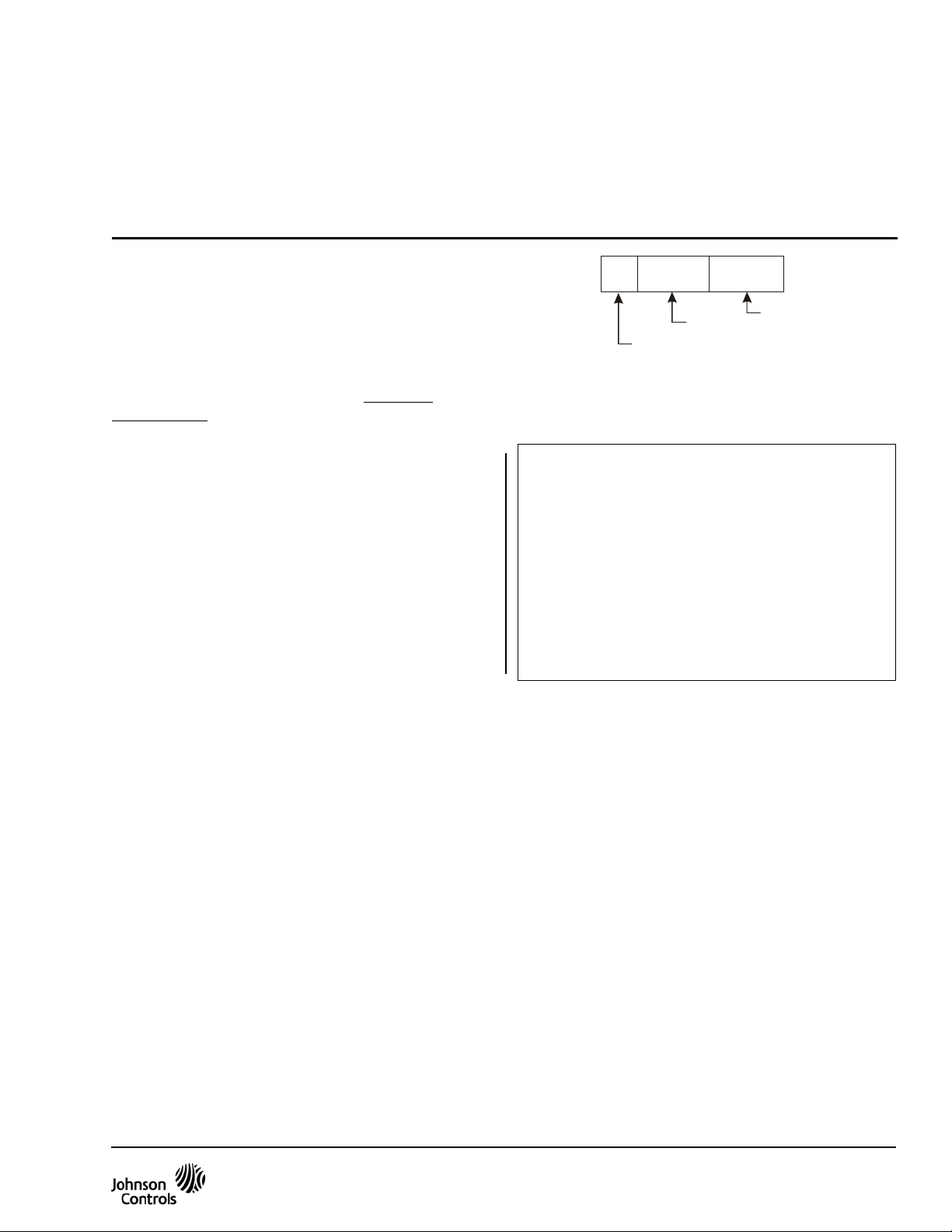
•the manufacturing date code of the valve (as
illustrated in Figure 1)
M
Manufacturin g Faci lity
Figure 1: Manufacturing Date Code
Year
w wy y
Week
fig:mfgdtcd
Installation
IMPORTANT: The VG7000 Series Bronze Control
Valves are intended to control saturated steam, hot
water, and chilled water flow under normal
equipment operating conditions. Where failure or
malfunction of the VG7000 Series Valve could lead
to personal injury or property damage to the
controlled equipment or other property, additional
precautions must be designed into the control
system. Incorporate and maintain other devices
such as supervisory or alarm systems or safety or
limit controls, intended to warn of or protect against
failure or malfunction of the VG7000 Series Valve.
Pre-installation Details
Before installing a VG7000 Series Bronze Control
Valve, please note the following:
• Be sure to mount the valve in an upright position, in
a conveniently accessible location.
• Protect the electric actuator from dripping water
that could enter the actuator housing and damage
the mechanism or motor.
• Do not cover the actuator with insulating material.
• Allow sufficient clearance to remove the actuator
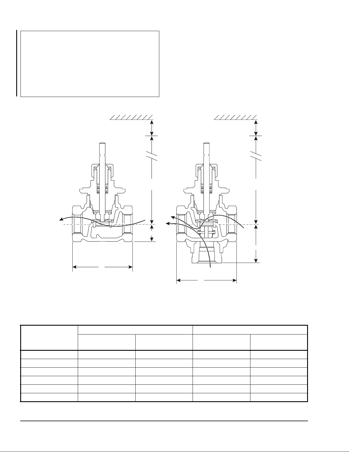
(refer to Figure 2 and Table 1 and Table 2).
• Pipe the valve with the flow in the direction of the
arrow on the valve body, so that the plug seats
against the flow.
• Wire all electrically actuated valve assemblies in
accordance with applicable electrical code
requirements. Input lines to the actuator must be
wired correctly for the valve to move in the proper
direction.
VG7000 Series Bronze Control Valves Installation Instructions 1
Page 2
IMPORTANT: Take care to prevent foreign materi al
such as weld slag, thread burrs, metal chips, and
scale from entering the piping system. This debris
can damage or severely impede the operatio n of the
valve by embedding itself in the seats, scoring the
valve, and ultimately resulting in seat leakage. If the
debris becomes embedded in the seats, subsequent
flushing and filtering of the piping system with the
valve installed does not remedy the problem.
Dimensions
Outlet
D
Valve + Actuator
Inlet
A
Clearance Needed
for Actuator Mounting
and Rem oval
C
B
D
Valve + Actuator
C
N.C.
(PDTC)
B
N.O.
(PDTC)
A
Fig:VG7000
Figure 2: Two-Way Norm ally Open (N.O.)/Push Down to Close (PDTC),
Two-Way Normally Closed (N.C.)/Push Down to Open (PDTO), and Three-Way Mixing Valve Dimensions,
Fluid Flow Directions, and Port Designations (Refer to Table 1 and Table 2.)
Table 1: National Pipe Thread (Internal NPT) Valve Dimensions, in. (mm)
Valve Size, in. (DN) A B
N.O., N.C., and
N.O. N.C. Three-Way
Three-Way
1/2 (DN15) 3 (76) 13/16 (21) 1-9/16 (39) 1-13/16 (46)
3/4 (DN20) 3-7/32 (81) 15/16 (24) 1-5/8 (41) 2-1/8 (54)
1 (DN25) 4-1/8 (104) 1-5/32 (29) 1-3/4 (44) 2-9/16 (65)
1-1/4 (DN32) 4-23/32 (119) 1-11/32 (34) 2 (51) 2-25/32 (70)
1-1/2 (DN40) 5-1/8 (130) 2-5/32 (55) 2-3/4 (70) 3-3/8 (85)
2 (DN50) 5-29/32 (150) 2-1/8 (53) 2-27/32 (72) 3-3/4 (95)
VG7000 Series Bronze Control Valves Installation Instructions2
Page 3
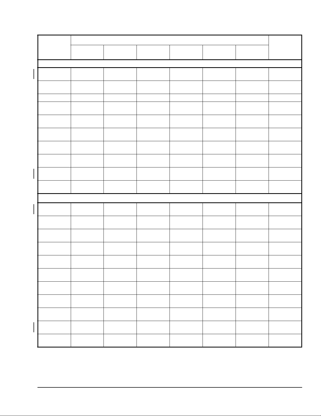
Table 2: Valve Assembly Dimensions, in. (mm)
Actuator
Type
Brass Trim Valve Assemblies
V-3000-8011 4-3/4
V-3000-8003 5-11/32
V-3801-8001 4 (102) 4 (102) --- --- --- --- 2-3/8 (60)
MP82xx,
MP83xx
VA-4233 8
VA-715x 7-11/16
VA-720x --- --- 9-19/32
VA-802x 6-7/16
M9116,
M9220
M1xx 10-13/16
Stainless Steel Trim Valve Assemblies
V-3000-8011 5-7/16
V-3000-8003 6-1/16
MP82xx 12-3/4
MP83xx 12-21/64
MP84xx --- --- --- --- 17-7/32
MP85xx --- --- --- --- 15-61/64
VA-4233 8-23/32
VA-715x 8-13/32
VA-720x 9-3/32
M9116,
M9220
M1xx 11-1/2
1/2 in.
(DN15)
(120)
(135)
--- --- 12-23/32
(203)
(195)
(164)
14
(356)
(274)
(138)
(153)
(324)
(313)
(221)
(214)
(231)
14-11/16
(373)
(292)
3/4 in.
(DN20)
4-3/4
(120)
5-11/32
(135)
8
(203)
7-11/16
(195)
6-7/16
(164)
14
(356)
10-13/16
(274)
2
5-7/16
(138)
6-1/4
(158)
13-17/64
(337)
12-35/64
(319)
8-15/16
(227)
8-5/8
(219)
9-5/16
(236)
14-29/32
(378)
1 1-23/32
(297)
(DN25)
5-31/32
15-7/32
12-1/32
6-19/32
13-39/64
8-31/32
9-21/32
12-1/16
1in.
(151)
6-9/16
(166)
(323)
9-7/32
(234)
8-5/8
(219)
(244)
--- --- --- --- 1-1/2
(386)
(305)
6
(152)
(167)
(346)
12-7/8
(327)
9-9/32
(236)
(228)
(245)
15-1/4
(387)
(306)
1
C
1-1/4 in.
(DN32)
5-7/8
(149)
6-19/32
(167)
12-27/32
(326)
9-7/32
(234)
8-5/8
(219)
9-5/8
(244)
15-7/32
(386)
12-1/32
(305)
6-1/4
(158)
6-27/32
(173)
13-27/32
(352)
13-1/8
(333)
9-13/16
(249)
9-7/32
(234)
9-7/8
(251)
15-1/2
(393)
12-5/16
(312)
1-1/2 in.
(DN40)
5-13/16
(147)
6-13/32
(162)
13-13/32
(341)
--- --- 1-1/2
9-5/32
(233)
9-15/16
(252)
15-1/16
(382)
11-7/8
(301)
--- --- 3-9/16
--- --- 3-9/16
14-1/32
(356)
13-19/64
(338)
(437)
(405)
--- --- 1-1/2
9-13/32
(239)
10-3/32
(256)
15-23/32
(399)
12-1/2
(318)
2in.
(DN50)
6-3/16
(157)
6-13/16
(172)
13-13/16
(351)
9-5/32
(233)
10-3/4
(273)
15-15/32
(392)
12-1/4
(311)
14-15/64
(361)
13-1/2
(343)
17-27/64
(443)
16-5/32
(410)
9-5/8
(244)
10-9/32
(261)
15-7/8
(403)
12-11/16
(322)
1
D
3-9/16
(90)
3-9/16
(90)
3-1/2
(89)
(38)
2-1/2
(64)
4-1/2
(114)
(38)
---
---
(90)
(90)
3-1/2
(89)
3-1/2
(89)
3-1/2
(89)
3-1/2
(89)
(38)
2-1/2
(64)
4-1/2
(114)
---
---
1. Dimension C is the overall height above the centerline of the valve body and dimension D is the clearance required for
actuator removal (as illustrated in Figure 2).
2. An extended bonnet comes as standard equipment on VG7000 Series Bronze Control Valves with stainless steel trim, to allow
for higher fluid temperatures (100 psig saturated steam at 338°F).
VG7000 Series Bronze Control Valves Installation Instructions 3
Page 4
E F
G
Fig:unionglobe
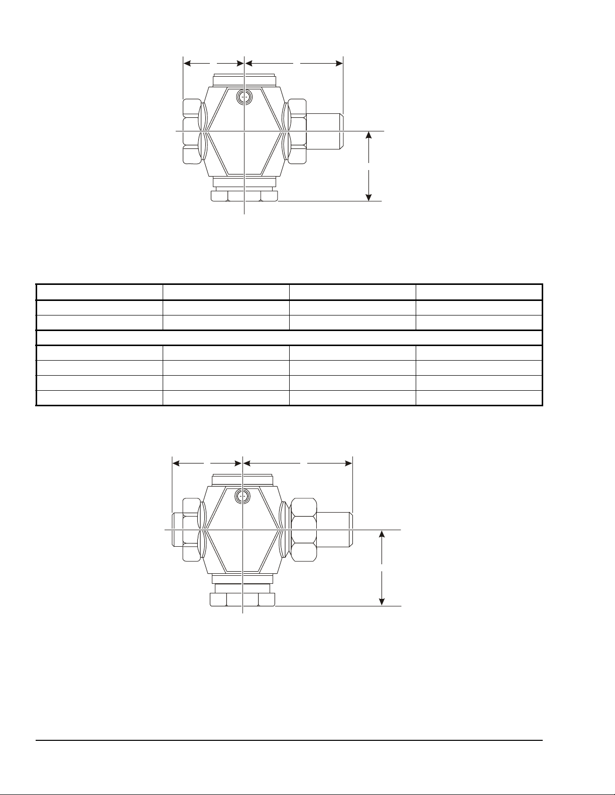
Figure 3: Two-Way N.O./PDTC and Two-Way N.C./PDTO Union Globe Valve Dimensions (Refer to Table 3.)
Table 3: Two-Way N.O./PDTC and Two-Way N.C./PDTO Union Globe Valve Dimensions, in. (mm)
1
Valve Size, in. (DN) E F G
1/2 (DN15) N.O./PDTC 1-1/2 (38) 2-21/32 (68) 13/16 (20)
1/2 (DN15) N.C./PDTO 1-1/2 (38) 2-21/32 (68) 1-17/32 (39)
Sizes Greater than 1/2 in. (DN15) are Available in N.O./PDTC Only
3/4 (DN20) N.O./PDTC 1-9/16 (40) 3-3/32 (79) 15/16 (24)
1 (DN25) N.O./PDTC 2-1/16 (53) 4-1/32 (102) 1-5/32 (29)
1-1/4 (DN32) N.O./PDTC 2-3/8 (60) 4-19/32 (117) 1- 11/32 (3 4)
1-1/2 (DN40) N.O./PDTC 2-9/16 (65) 4-27/32 (123) 2-5/32 (55)
1. Refer to Table2 for overall assembly height C and clearance D dimensions.
E F
Figure 4: Two-Way N.O./PDTC Union Angle Valve Dimensions (Refer to Table 4.)
G
Fig:unionangle
VG7000 Series Bronze Control Valves Installation Instructions4
Page 5
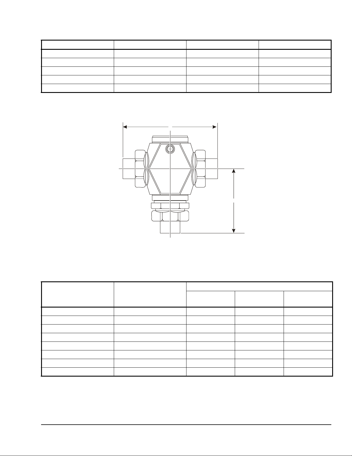
Table 4: Two-Way N.O./PDTC Union Angle Valve Dimensions , in. (mm)
1
Valve Size, in. (DN) E F G
1/2 (DN15) N.O./PDTC 1-23/32 (44) 2-21/32 (68) 1-7/8 (48)
3/4 (DN20) N.O./PDTC 1-9/16 (40) 3-3/32 (79) 2-1/8 (54)
1 (DN25) N.O./PDTC 2-1/16 (53) 4-1/32 (102) 2-9/16 (65)
1-1/4 (DN32) N.O./PDTC 2-3/8 (60) 4-19/32 (117) 2-25/32 (70)
1-1/2 (DN40) N.O./PDTC 2-9/16 (65) 4-27/32 (123) 3-3/8 (85)
1. Refer to Table 2 for overall assembly height C and clearance D dimensions.
A
B
Fig:unionsweat
Figure 5: Two-Way N.O./PDTC, Two-Way N.C./PDTO, and Three-Way Mixing Union Sweat Valve
Dimensions (Refer to Table 5.)
Table 5: Two-Way N.O./PDTC, Two-Way N.C./PDTO, and Three-Way Mixing Union Sweat Valve
Dimensions, in. (mm)
1
Valve Size, in. (DN) A B
Two-Way N.O./
PDTC
1/2 (DN15), 3/8 in. Tubing 4-3/16 (106) 13/16 (20) 1-17/32 (39) 2-17/32 (64)
1/2 (DN15), 1/2 in. Tubing 4-3/16 (106) 13/16 (20) 1-17/32 (39) 2-17/32 (64)
1/2 (DN15), 3/4 in. Tubing 4-25/32 (122) 13/16 (20) 1-17/32 (39) 2-17/32 (64)
3/4 (DN20) 5-1/16 (129) 15/16 (24) 1-9/16 (40) 3-1/4 (82)
1 (DN25) 6-3/32 (155) 1-5/32 (29) 1-3/4 (44) 3-23/32 (94)
1-1/4 (DN32) 7-9/32 (185) 1-11/32 (34) 2 (51) 4-3/32 (104)
1-1/2 (DN40) 8-19/32 (218) 2-5/32 (55) 2-3/4 (70) 4-29/32 (125)
2 (DN50) 9-7/16 (240) 2-1/8 (53) 2-27/32 (72) 5-19/32 (142)
Two-Way N.C./
PDTO
Three-Way
Mixing
1. Refer to Table 2 for overall assembly height C and clearance D dimensions.
VG7000 Series Bronze Control Valves Installation Instructions 5
Page 6
Repair Information
If the VG7000 Series Bronze Control Valve fails to
operate within its specifications, refer to the VG7000
Series Bronze Control Valves Product Bulletin
(LIT-977140) for a list of repair parts and re conditioning
kits available. For a replacement valve, contact the
nearest Johnson Controls® representative.
Pre-Servicing Details
Before servicing a VG7000 Series Bronze Control
Valve, please isolate or disconnect the pneumatic
supply or electrical power to the actuator and note the
following:
WARNING: Risk of Electric Shock.
Disconnect each of multiple power
!
supplies before making electrical
connections. More than one disconnect
may be required to completely deenergize equipment. Contact with
components carrying hazardous voltage
can cause electric shock and may result
in severe personal injury or death.
CAUTION: Risk of Property Damage.
Do not apply power to the system before
!
!
checking all wiring connections. Short
circuited or improperly connected wires
may result in permanent damage to the
equipment.
WARNING: Risk of Personal Injury.
Shut off the liquid supply and relieve
pressure in the line before servicing the
valve. Contents of liquid lines could be
under pressure and the release of liquid
under pressure may cause severe
personal injury.
Valve Removal Details
In addition to observing general mounting guidelines
and National Code Standards, be sure to note the
following before removing a valve from a piping
system:
• Allow hot water or steam systems to cool down
thoroughly before proceeding.
IMPORTANT: Make all wiring connections in
accordance with local, national, and regional
regulations. Do not exceed the electrical ratings of
the VG7000 Series Bronze Control Valve.
• Drain the piping system to provide a pressure-free
work environment.
• Vent al l piping systems that are used in conjunction
with corrosive or aggressive fluids.
• Be sure all work is performed by qualified
personnel only.
VG7000 Series Bronze Control Valves Installation Instructions6
Page 7
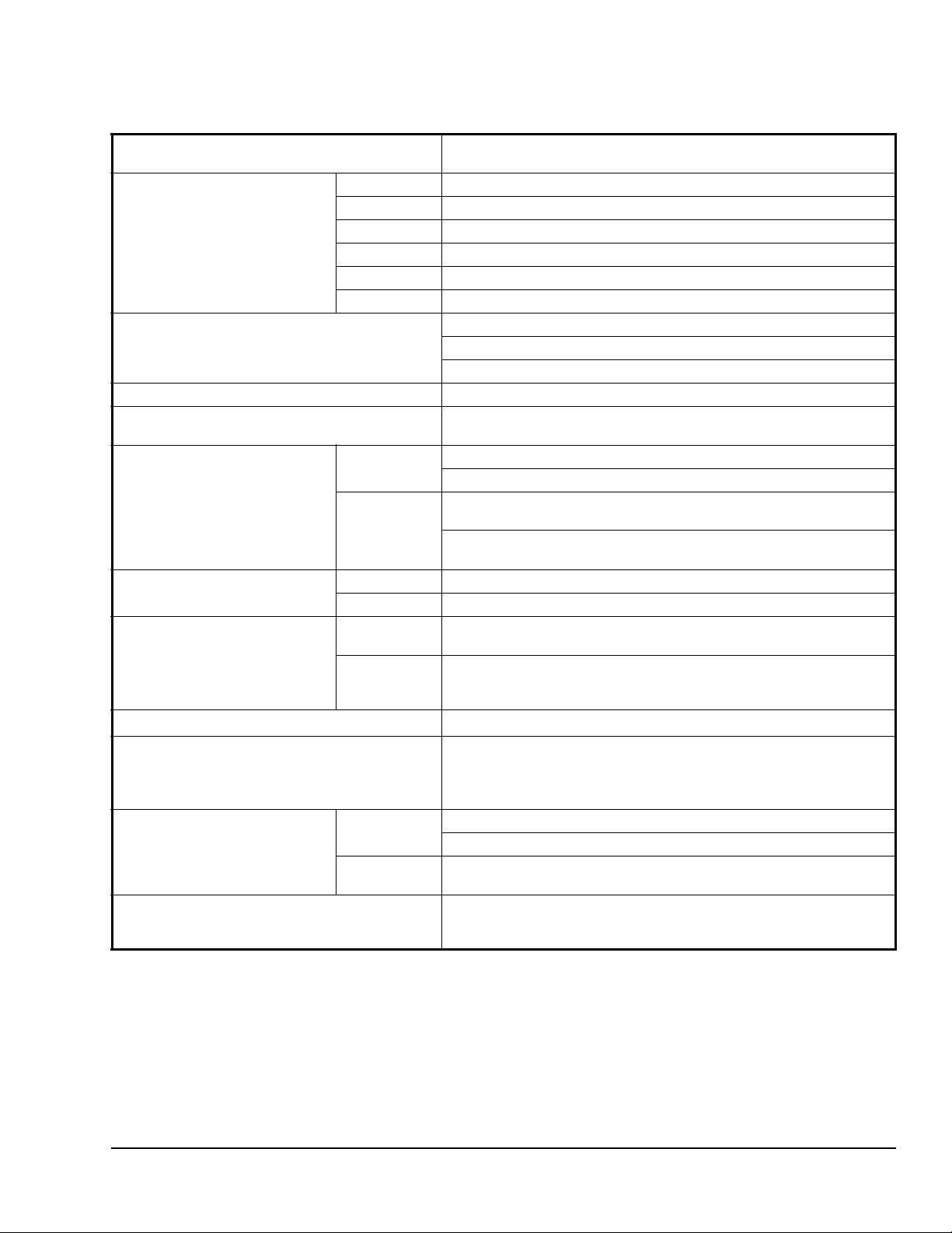
Technical Specifications
VG7000 Series Bronze Control Valves (Part 1 of 2)
Service
Valve Body Size/Cv (kv) 1/2 in. 0.73 (0.63), 1.8 (1.6), and 4.6 (4.0)
Valve Stroke 5/16 in. (8 mm) for 1/2 or 3/4 in. Valves
Valve Body Rating Meets requirements of ANSI B16.15, Class 250 (EN 12360).
Valve Ambient Operating
Temperature Limits
Valve Assembly Maximum
Allowable Pressure/
Temperature
Leakage Brass Trim 0.01% of Maximum Flow per ANSI/FCI 70-2, Class 4
Inherent Flow Characteristics Two-Way
Rangeability
Spring Range Pneumatic
Actuators
Maximum Recommended
Operating Pressure Drop
Maximum Actuator Supply
Pressure (Pneumatically
Actuated Valves Only)
1
3/4 in. 7.3 (6.3)
1 in. 11.6 (10)
1-1/4 in. 18.5 (16)
1-1/2 in. 28.9 (25)
2 in. 46.2 (40)
Steam Brass Trim: 35 psig (241 kPa) Saturated Steam at 281°F (138°C)
Water Brass Trim: 400 psig (2,756 kPa) up to 150°F (66°C), Decreasing to
SS Trim 0.05% of Maximum Flow
Valves
Three-Way
Mixing
Valves
2
Steam Brass Trim: 15 psig (103 kPa) for All Valve Sizes
Water Brass and SS Trim: 35 psig (241 kPa) for 1/2 through 1-1/4 in. Valves;
Hot Water, Chilled Water, 50/50 Glycol Solutions, or Steam for HVAC
Systems (Fluid Group 1 According to 67/548/EEC)
1/2 in. (13 mm) for 1 and 1-1/4 in. V a lves
3/4 in. (19 mm) for 1-1/2 and 2 in. Valves
35 to 150°F (2 to 65°C)
SS Trim: 100 psig (690 kPa) Saturated Steam at 338°F (170°C)
365 psig (2,515 kPa) at 248°F (120°C)
SS Trim: 400 psig (2,756 kPa) up to 150°F (66°C), Decreasing to
308 psig (2,122 kPa) at 338°F (170°C)
Equal Percentage
Linear
25:1 for All Sizes (EN 60534-2-4)
3 to 6 psig (21 to 41 kPa) for All Except MP8000;
3 to 7 psig (21 to 48 kPa) for MP8000 Only;
4 to 8 psig (28 to 55 kPa);
9 to 13 psig (62 to 90 kPa)
SS Trim: 100 psig (690 kPa) for All Valve Sizes
30 psig (207 kPa) for 1-1/2 and 2 in. Valves
25 psig (172 kPa) Maximum
VG7000 Series Bronze Control Valves Installation Instructions 7
Page 8
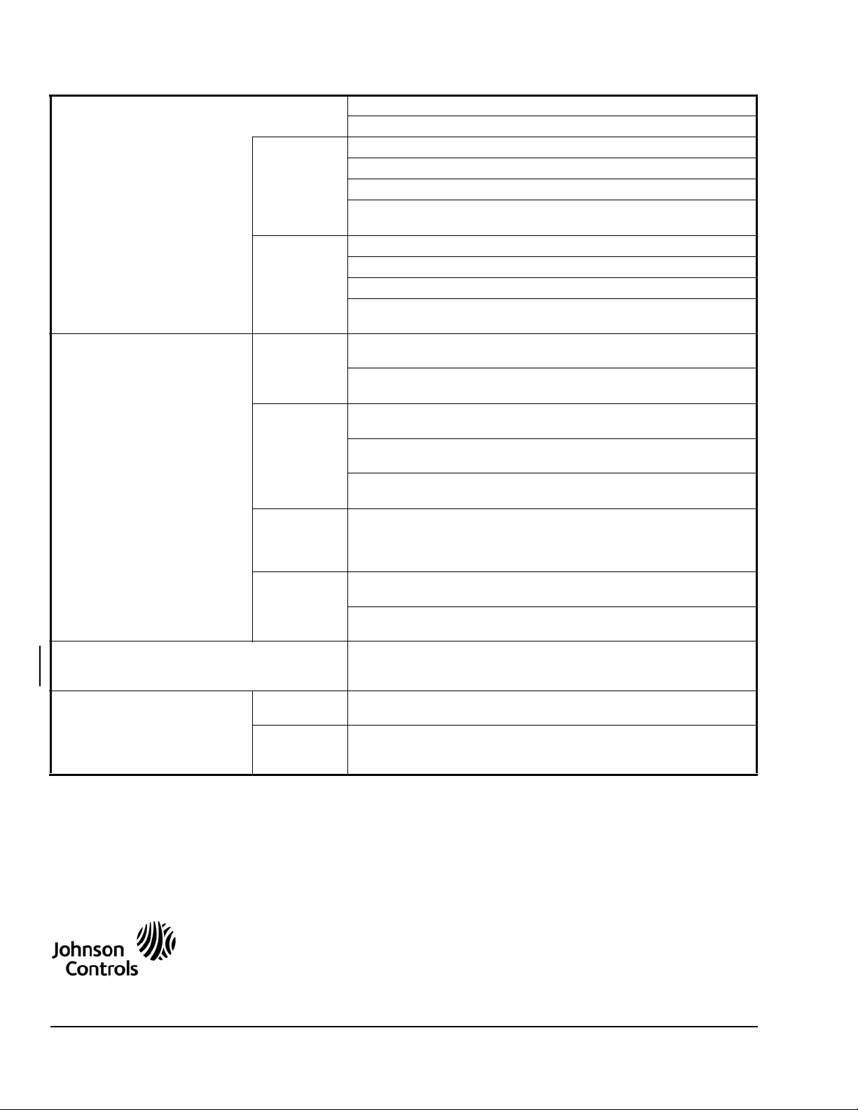
VG7000 Series Bronze Control Valves (Part 2 of 2)
Materials Body: Cast Bronze
Bonnet: Brass
Brass Trim Stem: Stainless Steel
Plug: Brass
Seat: Brass Against Molded Elastomeric Disk
Packing: Self-Adjusting Ethylene Propylene Rubber (EPR) Ring Pack
U-Cups
SS Trim Stem: Stainless Steel
Plug: Stainless Steel
Seat: Stainless Steel
Packing: Spring Loaded Polytetrafluoroethylene (PTFE) and
Elastomer V-Rings
Valve Fluid Operating
Temperature Limits
Actuator Ambient Operating
Temperature Limits
Compliance 1/2, 3/4, and
Brass Trim
Valve with
Pneumatic
Actuator
Brass Trim
Valve with
Electric
Actuator
SS Trim
Valve with
Pneumatic
Actuator
SS Trim
Valve with
Electric
Actuator
1 in. Valves
1-1/4, 1-1/2,
and 2 in.
Valves
For V-3801-8001 and V-3000-8003 Actuators:
35 to 248°F (2 to 120°C) Water; 15 psig (103 kPa) Saturated Steam
For MP82 and V-3000-8011 Actuators:
35 to 284°F (2 to 140°C) Water; 38 psig (262 kPa) Saturated Steam
For VA-8x2x Actuators:
195°F (91°C) Maximum Water; Actuators are not rated for steam.
For VA-4233-xGx-2 Actuators:
35 to 250°F (2 to 121°C) Water; 15 psig (103 kPa) Saturated Steam
For All Other Electric Actuators:
35 to 284°F (2 to 140°C) Water; 38 psig (262 kPa) Saturated Steam
All Pneumatic Actuators:
35 to 338°F (2 to 170°C) Water; 100 psig (690 kPa) Saturated Steam
For VA-4233-xGx-2 Actuators:
35 to 250°F (2 to 121°C) Water; 15 psig (103 kPa) Saturated Steam
For All Other Electric Actuators:
35 to 338°F (2 to 170°C) Water; 100 psig (690 kPa) Saturated Steam
Refer to the appropriate actuator or linkage kit product bulletin. Ambient
operating temperature or other service limitations vary by selected
actuator.
Pressure Equipment Directive (PED) 97/23/EC:
Paragraph 3, Comma 3 (CE Marki ng is not applicable.)
Pressure Equipment Directive (PED) 97/23/EC:
Category 1, Mod. A (Subject to CE Marking)
1. Proper water treatment is recommended; refer to VDI 2035 Standard.
2. Rangeability is defined as the ratio of maximum flow to minimum controllable flow.
The performance specifications are nominal and conform to acceptable industry standards. For application at conditions beyond these
specifications, consult the local Johnson Controls office. Johnson Controls, Inc. shall not be liable for damages resulting from misapplication or
misuse of its products.
Building Efficiency
507 E. Michigan Street, Milwaukee, WI 53202
Metasys® and Johnson Controls® are registered trademarks of Johnson Controls, Inc.
All other marks herein are the marks of their respective owners. © 2008 Johnson Controls, Inc.
VG7000 Series Bronze Control Valves Installation Instructions8
Published in U.S.A. www.johnsoncontrols.com
 Loading...