

Johnson Controls VA-7010 Series, VG5000, VA-7010-8001, VA-7010-8002, VA-7010-8003 Product/technical Bulletin
...Page 1
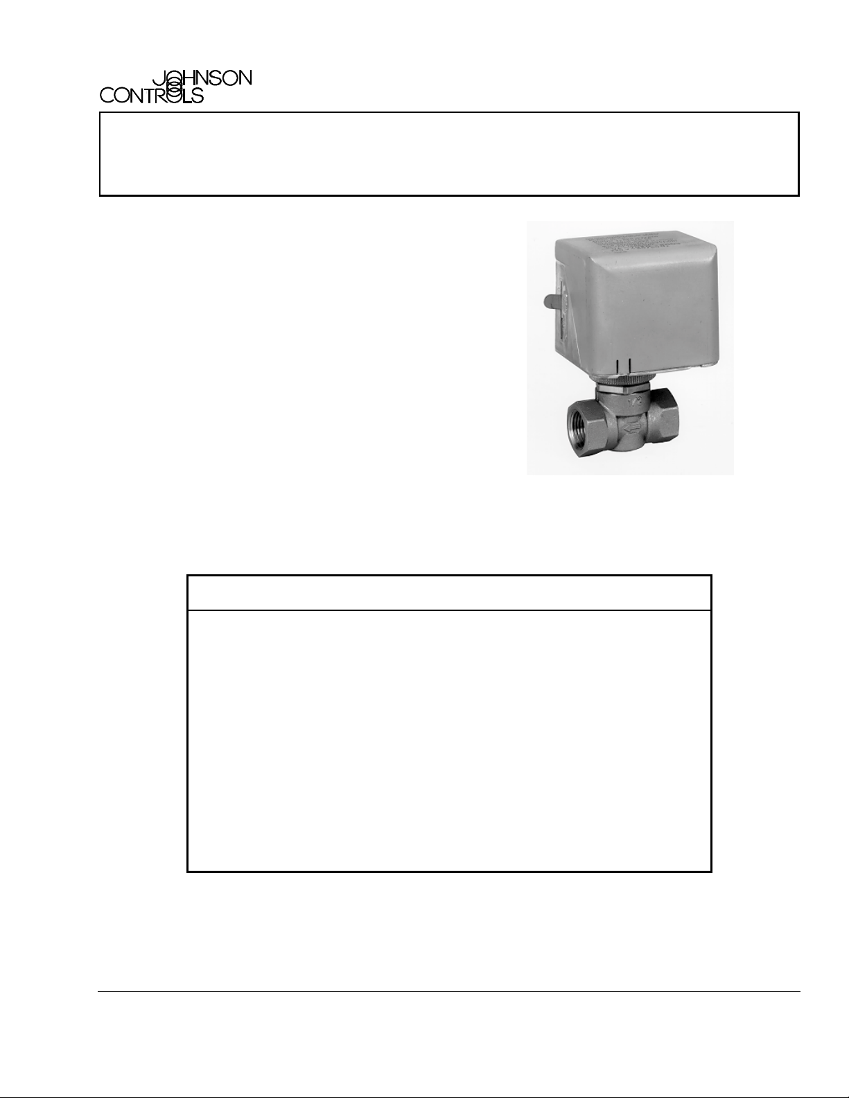
VA-7010 Series Electric On/Off Actuator
The VA-7010 Series E lec tric On/Off Actuators provide
two-posit ion ( open/closed) contr ol and c an eas ily be
field mounted with a threaded coupling onto V G5000
Series Forged Bras s V alv es . Refer to t he
Series Forged Brass Valves 1/2 Thr ough 1 in.,
Two-Way Nor mally Closed and Three-Way
Product/Technical Bulletin
information.
A lever at the side of the actuat or hous ing c an be us ed
to open the mounted valv e m anually for servicing.
(LIT-977135
VG5000
) for specific
FANs 977, 1628.3
Product/Technical Bulleti n VA-7010
Issue Date 0199
Figure 1: VA-7010 Actuator with VG5000 V alve
Features and Benefits
❑
Low or Line Voltage Model
Available
❑
AC Stall Type Motor Ensures quiet operati on
❑
Manual L ever Allows manual posi tion m ode for servici ng
❑
Flat Profile Design with
Small Side Clearance
❑
Actuator can be Mounted
after Valve Bod y is
Installed
❑
Actuator can be Rotated
after Mounting
Provides application flexibility
Prov ides mounti ng c lose to flat surfac es;
saves space
Simplifies instal lation in confined spaces;
allows application flexibility
Prov ides easier wiring by locating the wiring
conduit entr y in any direction
© 1999 Johnson Controls, Inc.
Part No. 34-636-763, Rev. B www.johnsoncontrols.com
Code No. LIT-977360
1
Page 2
peration
O
When power is applied to the actuator, the motor drives
the gear assembly, and pushes down on the valve stem
against the force of the valve return spring.
When power i s removed from the actuat or , the
actuator ret r ac ts and allows the valve return spring to
move the valve stem up, in the di r ec tion of its norm al
position. ( S ee Figure 2.)
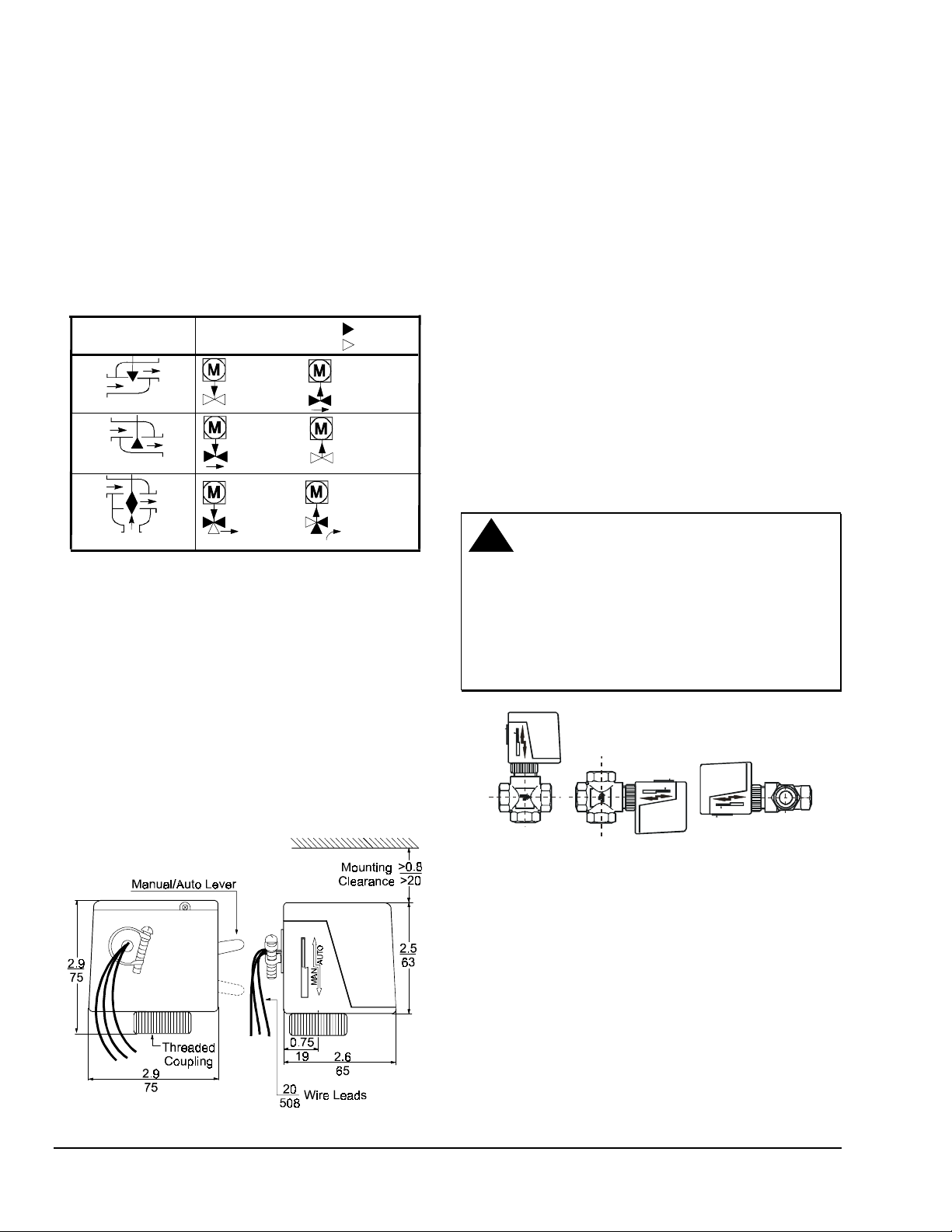
Valve Type
2-way N.O., PDTC
Stem Mo vement/Flow
Actuator On
= Flow
= No Flow
Actuator Off
ounting
M
Observe the fol lowing recom mendations when
mounti ng the actuator:
• Make sure the actuator is easily accessibl e for the
electrical connect ions.
• Make sure the actuator is free of thermal
insulati on materi al.
• Leave at least 0.8 in. ( 20 mm) c learance above
the actuator for m ounting purposes. (See Figure
3.)
To mount the actuator on a VG5000 v alv e:
1. Place the thr eaded c oupling over the valve stem
and the bonnet.
2-way N.C., PDTO
3-way, Mixing
Note: Push Do wn to Close (P DTC)
Push Down to Open (PDTO)
Figure 2: Flow D ia gr a m
anual Override
M
The VA-7010 actuator feat ur es a manual operating
lever (shown in Figure 3) for m anually openi ng
Normally Closed (N.C. ) valves or t he N.C. port of
3-way valves. The lever will not fully close Normally
Open (N.O.) valves or the N.O. port of 3-way valves.
imensions
D
Actuator On
Actuator On
Actuator Off
Actuator Off
2. Rotate the actuator to the desired posit ion and
tighten t he c oupling securely by hand.
Note: Never use the ac tuator as a mounting lever.
!
CAUTION: Equipment Damage Hazard.
Mount only on a valve t hat is
piped within 90° of the vertical
position, so i t is free of dri pping
water, which could ent er the
housing and damage the
mechanism and motor. (See
Figure 4.)
Figure 4: Valve/Actuator Mounting Positions
Figure 3: Dimensions, in. (mm)
2 VA-7010 Series Electric On/Off Ac tuator Product/Technical Bulletin
Page 3

W
iring
!
WA RNING:Electrical S hock Hazard.
When servic ing, m ak e sure t hat
the electr ical supply to the
actuator i s switched off to avoid
personal injur y or shock. Do not
attempt to connect or disconnect
wires when the power is on.
rdering Information
O
VA-7010-80 0
Sup ply Voltage
1
2
3
6
7
Figure 6: Ordering Data for the VA-7010
24 VAC
120 VAC
230 VAC
208 VAC
277 VAC
!
CAUTION: Equipment Damage Hazard.
Check all wir ing connections
before appl y ing power to the
system. Short - c ircuit ed or
improper ly connected wir es wil l
result in permanent dam age to
the equipm ent.
IMPORTA NT: Make all wiring connecti ons i n
accordance with the National
Electrical Code and al l local
regulati ons.
To wire the VA-7010 ac tuator:
1. Run the actuator wires through 3/8 in. Flexi ble
Metallic Conduit (FMC) or i ts equiv alent as
appropriate.
2. Secure the FMC to t he c onnec tor provided with
the actuator by tighteni ng the clamp screw using a
1/4 in. flat- blade screwdriver.
3. Connect the wires as shown in Figure 5 f or eac h
respective model v oltage.
208
VAC
White
Red
277
VAC
White
Blue
VA-7010
Power
Power
Power
24
VAC
White
White
120
VAC
White
Black
230
VAC
White
Ye l lo w
Actuator Combinations
The VA-7010 Series Electric Valve Act uators are
designed to be used with the VG5000 valve series.
Refer to the VG5000 Seri es For ged B r ass Valves
Product/Technical Bulletin (LIT-977135)
ordering inform ation.
for complete
N/A
Green
Green
Green
Green
Figure 5: VA-7010 Wiring Diagram
VA-7010 Series Electric On/Off Ac tuator Product/Technical Bulletin 3
Case
Ground
Page 4

pecifications
S
Product
Action
Type of Motor
Supply Voltage (50/60 Hz)
Power Consumption
Minimum For ce
Nomin al Stroke
Full Stroke Time On
Full Stroke Time Off
Enclosure
Ambient Oper at ing
Condition
Ambient St or age
Condition
Electrical Connecti ons
Dimensions (H x W x D)
Shipping Weight
Agency Compliance
CE Conformit y
VA-7010 Series Electric On/Off Actuator
On/Off
Synchronous Stall
VA-7010-8001: 24 VAC, Class 2, ±10%
VA-7010-8002: 120 VAC, ±10%
VA-7010-8003: 230 VAC, ±10%
VA-7010-8006: 208 VAC, ±10%
VA-7010-8007: 277 VAC, ±10%
7 VA
20.2 lb (90 N)
0.12 in. (3 mm), maximum 0.2 in. (5 mm)
Nominal 10 seconds
Nominal 5 seconds
IP40, NEMA 1
35 to 122°F (2 to 50°C), non-condensing
-4 to 149°F (-20 to 65°C), non-condensing
18 AWG, 20 in. (508 m m) long wir e leads
2.9 x 2.9 x 2.6 in. (75 x 75 x 65 mm)
1.1 lb (0.5 kg)
UL 873 Listed, File E27734, G uide XAPX, Plenum Rated
CSA C22.2 No. 139 Certified, File LR85083, Class 3221 01
VA-7010-8001: EMC Directive (89/336 EU)
The performance specifications are nominal and conform to acceptable industry standards. For application at conditions beyond these
specifications, consult the local Johnson Controls office. Johnson Controls, Inc. shall not be li able for damages resulting from misapplication or
misuse of its products.
Controls Group
507 E. Michigan Street
P.O. Box 42 3 Printed in U.S.A.
Milwaukee, WI 53201 www.johnsoncontrols.com
4 VA-7010 Series Electric On/Off Ac tuator Product/Technical Bulletin
 Loading...